Table of Contents

Related Manuals for emz smart Stove


Summary of Contents for emz smart Stove
- Page 1 OPERATING AND INSTALLATION INSTRUCTIONS DIFFERENTIAL TEMPERATURE CONTROLLER FOR ROOM/SPACE HEATING SYSTEMS AND DOMESTIC HOT WATER SYSTEMS HANDLING SOLID FUEL HEAT SOURCES, NAMELY WOOD LOG AND PELLET STOVES emz - THE SMILING COMPANY...
- Page 2 Non-authorized disclosure, reproduction, divulgation or editing of this documentation, as well as exploitation, utilization or publication, are prohibited. The rights to the word and design marks ›emz - smart solutions‹ and ›smart Stove‹ are the exclusive property of emz-Hanauer GmbH & Co.KGaA.
-
Page 3: Table Of Contents
Connection of hydraulic system 7 ..................23 Functions for stove control ....................... 24 Fire detection ..........................24 Fire detection with pellet stove....................24 Dynamic pump delay (DPD......................24 Dynamic pump control ........................ 24 Overtemperature protection ......................25 smart Stove - 0142 - 42WMSUGAT2-C... - Page 4 Connection of a boiler to REL .....................47 Connection of an external heat source to REL ................47 Blocking connection of an external heat source to REL..............48 Blocking connection of a pump to RO2..................48 Connection for request for heat to RO1 ..................48 smart Stove - 0142 - 42WMSUGAT2-C...
- Page 5 Example for malfunction ......................74 Replacement of fuse ........................78 Technical data..........................80 Differential temperature controller smart Stove ................80 Connection to power supply......................80 Max. cross sections to be connected..................80 Interfaces TS1 / TS2 / TS3 / TS4 / TS5 / TS6................80 Interface TS7 / TS8........................
- Page 6 TABLE OF CONTENTS Index ..............................87 smart Stove - 0142 - 42WMSUGAT2-C...
-
Page 7: Important Information
Conditions of use These instructions describe installation, commissioning, operation, repair, and disassembly of the differential temperature controller smart Stove for solid fuel heat sources, namely wood log and pel- let stoves. For operation of the entire plant, the technical documentation of all the components used such as stove, boiler, tank, pumps, mixers, and valves, etc. -
Page 8: Intended Use
A device with damaged housing must not be operated! Intended use The differential temperature controller smart Stove may be used exclusively for controlling heating and water temperatures for use with hydrophilic wood log and pellet stoves in combination with one or more buffer tanks. -
Page 9: Description
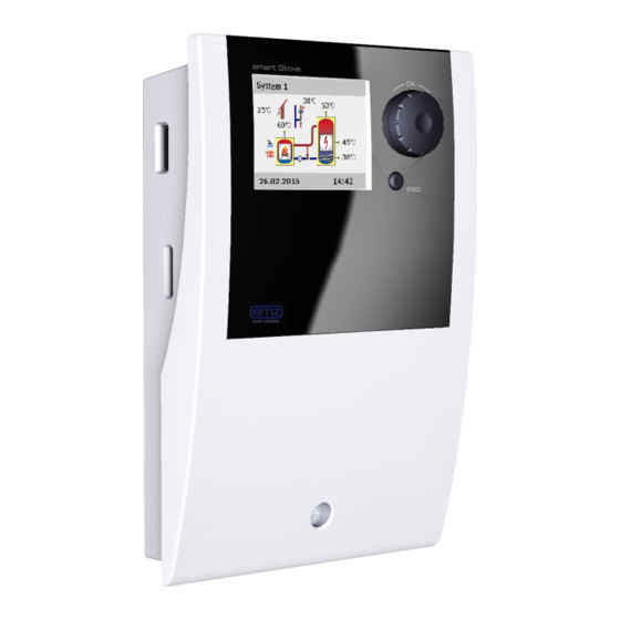
DESCRIPTION Description The differential temperature controller smart Stove is an independent electronic controller for con- trolling heating and water temperatures for use with hydrophilic wood log and pellet stoves in combi- nation with one or more buffer tanks. The controller is equipped with a robust three-part plastic housing which can only be opened by means of tools (screw driver PH2). -
Page 10: Data Interfaces
Micro SD card must be formatted with a PC. NOTICE Micro SD cards recommended by the manufacturer: ® Transcend 2GB Product-No. TS2GUSDC ® Transcend 4GB HC ® Transcend 1GB Verbatim 2GB PNY 2GB hp 2GB SanDisk 2GB smart Stove - 0142 - 42WMSUGAT2-C... -
Page 11: Data Logging
• Output states (speed) of RO1, RO2, REL, TS7, TS8 • Lock-states (safety functions) • Error codes In the header of each file the date, the controller ID, as well as the column label of the recording data is applied. smart Stove - 0142 - 42WMSUGAT2-C... -
Page 12: Operation Of The Controller
OPERATION OF THE CONTROLLER Operation of the controller Control elements The entire set-up and operation of the differential temperature controller smart Stove is effected via only two control elements on the device front. Knob with OK button Display esc button All settings and interrogations are effected via the knob and the esc button. -
Page 13: Display
Display For indication of the operating mode and for communication in case of set-up, malfunction, modifica- tion and evaluation, the differential temperature controller smart Stove is equipped with a coloured full graphics display which is permanently backlit. The display is active as long as there is supply voltage on the controller. -
Page 14: Communication Screen
To return to the information screen, press the esc button. Communication screen When you press the knob while the information screen is shown, the communication screen will be displayed. It shows the menu of selectable functions and parameters. “Menu structure” on page 31 smart Stove - 0142 - 42WMSUGAT2-C... - Page 15 Check box Start Submenu arrow Selection menu Timer,thermostat Active menu item Sensor Output Scroll arrow 17.03.2016 10:35 Date and time USB connection symbol (Example) To return to the information screen, press the esc button. smart Stove - 0142 - 42WMSUGAT2-C...
-
Page 16: Hydraulic Systems
If you want to complete an existing system or replace the exist- ing controller, please make sure that smart Stove is compatible with the existing configuration! The sensors are connected to TS1 to TS6, pumps and valves are connected to RO1/RO2/REL/TS7/TS8 - The interfaces are assigned to the functions in question on commissioning. -
Page 17: Hydraulic System 1: Wood Log Stove
REL” on Blocking of space heating pump Tank sensor, middle page 47 (230 V AC), see “Blocking connection of Tank sensor, bottom a pump to RO2” on page 48 smart Stove - 0142 - 42WMSUGAT2-C... -
Page 18: Hydraulic System 2: Wood Log Stove, Tank With Zone Valve
Charging pump (230 V AC) an external heat source to REL” on Zone valve (230 V AC), see “Connection Tank sensor, middle page 47 of a zone valve to RO1/RO2” on page 46 Tank sensor, bottom smart Stove - 0142 - 42WMSUGAT2-C... -
Page 19: Hydraulic System 3: Wood Log Stove, Tank With Charging Zones, External Domestic Hot-Water Tank
Tank sensor, middle nection of a Zone valve (230 V AC), see “Connection pump to REL” on Tank sensor, bottom of a zone valve to RO1/RO2” on page 46 page 47 Domestic hot-water pump smart Stove - 0142 - 42WMSUGAT2-C... -
Page 20: Hydraulic System 4: Pellet Stove With Combination Tank
48 source to REL” on Tank sensor, middle Blocking of space heating pump page 47 (230 V AC), see “Blocking connection of a Tank sensor, bottom pump to RO2” on page 48 smart Stove - 0142 - 42WMSUGAT2-C... -
Page 21: Hydraulic System 5: Pellet Stove
REL” on Tank sensor, middle RO1” on page 48 page 47 Tank sensor, bottom Blocking of space heating pump (230 V AC), see “Blocking connection of a pump to RO2” on page 48 smart Stove - 0142 - 42WMSUGAT2-C... -
Page 22: Hydraulic System 6: Pellet Stove With External Additional Heating
Request for heat (230 V AC), see Tank sensor, top tion according to “Connection for request for heat to page 47 Tank sensor, middle RO1” on page 48 Additional heating pump (230 V AC) Tank sensor, bottom smart Stove - 0142 - 42WMSUGAT2-C... -
Page 23: Hydraulic System 7: Pellet Stove, Tank With Charging Zones, External Domestic Hot-Water Tank
RO1” on page 48 pump to REL” on Tank sensor, bottom page 47 Domestic hot-water pump Zone valve (230 V AC), see “Connection of a zone valve to RO1/RO2” on page 46 smart Stove - 0142 - 42WMSUGAT2-C... -
Page 24: Functions For Stove Control
The control of the pump is triggered by fulfilling a separate set-point (›Charge start‹ + ›Charge off- set‹) and the product of an increment factor with the minimum pump speed. The following diagram illustrates the dynamic pump delay and dynamic pump control. smart Stove - 0142 - 42WMSUGAT2-C... -
Page 25: Overtemperature Protection
The temperature limits can be changed in professional mode, see “Basic functions” on page 55. NOTICE In order to avoid overheating, the wood log or pellet stove must be equipped with its own overtemperature protection. smart Stove - 0142 - 42WMSUGAT2-C... -
Page 26: Antifreeze Protection
The parameters for additional heating can be set in professional mode, see “Basic functions” on page 55. smart Stove - 0142 - 42WMSUGAT2-C... -
Page 27: Request For Heat
If it is enabled for providing heat, fire will be detected and displayed, similar to wood log stove. Request for additional heater is working in the same way as in wood log schemes. smart Stove - 0142 - 42WMSUGAT2-C... -
Page 28: Thermostat Functions
T ON > T OFF The output is activated once the ›T ON‹ temperature is reached, and deactivated T ON once the ›T off‹ temperature is reached. T OFF Timer function The output is activated within a selected time 8:00 9:00 frame. smart Stove - 0142 - 42WMSUGAT2-C... -
Page 29: Timer Thermostat
+ hysteresis or the upper limit - hysteresis ±1K T ON is reached. • The output is switched OFF when the upper limit - hysteresis or the lower limit + hysteresis is reached. smart Stove - 0142 - 42WMSUGAT2-C... -
Page 30: Automatic Operation
There is no need for intervention by the installer or operator. 17.03.2016 09:34 NOTICE Check the display screen of the smart Stove on a regular basis to be able to eliminate any malfunctions promptly! smart Stove - 0142 - 42WMSUGAT2-C... -
Page 31: Settings During Operation
Items marked by an asterisks * are only available in professional mode, see page 54. NOTICE The controller does not display any sub menus which are not required by either the selected hydraulic schema or by the acti- vated options. smart Stove - 0142 - 42WMSUGAT2-C... -
Page 32: Main Menu
Select a subitem by pressing the knob. About SmartStove 17.03.2016 10:14 Evaluation The ›1. Evaluation‹ menu provides information about the differ- 1.1 Evaluation ential temperature controller smart Stove and the entire plant. Measured values Service hours Error list 17.03.2016 10:24 Select ›Measured values‹. - Page 33 Select ›Error list‹. 1.1.5 Error list The ›Error list‹ shows all the error messages of the differential M05: 08:31 03.09 temperature controller smart Stove in a temporal order. M04: 07:44 03.09 To view information for an error message, select it. 17.03.2016...
-
Page 34: Settings
Here, date and time can be set in case of deviation or an 1.2.1 Time/Date extended period of de-energizing. Date 17.03.2016 If the differential temperature controller smart Stove is installed Time 10:23 at a location where daylight-saving time exists, the time shift Auto. Clock Change can be activated by ›Auto Clock Change‹. - Page 35 ›Error‹: Acoustic signal for alarms Add. heat alert ›Add. heat alert‹: Acoustic signal on request for additional Stove request heat, see page 27 ›Stove request‹: Acoustic signal on request for heat from stove 17.03.2016 10:34 smart Stove - 0142 - 42WMSUGAT2-C...
-
Page 36: Basic Functions
In professional mode, presettings must be made to this effect - Thermostat HETS8 your installer will explain the appropriate function to you, if nec- essary. By selecting a subitem ... 17.03.2016 10:44 1.3.1 Thermostat H..the appropriate activation screen is displayed. Activation 17.03.2016 10:44 smart Stove - 0142 - 42WMSUGAT2-C... - Page 37 100min*K ›DRD DHW Comf‹ is the dynamic recharge delay for domestic DRD DHW Comf hot water in comfort mode. 10min*K 17.03.2016 10:44 Return to ›1 Main menu‹. Select ›Monitoring‹. smart Stove - 0142 - 42WMSUGAT2-C...
-
Page 38: Monitoring
11:04 1.1.5 Error list The ›Error list‹ shows all the error messages of the differential M33: 09:31 03.07 temperature controller smart Stove in a temporal order. M32: 09:44 03.07 To view information for an error message, select it. 17.03.2016 11:04 1.1.5 Error list... -
Page 39: About
11:04 System If no entry is made within the preset time (30 - 255 s) on the System 1 smart Stove, the display returns to ›System‹. Use ›esc‹ to return to the home screen from every menu. 17.03.2016 11:04 smart Stove - 0142 - 42WMSUGAT2-C... -
Page 40: Mounting
DANGER Electrical hazard Lethal danger due to electrocution! Whenever work is performed on the open terminal cover, all poles of the power supply must be disconnected reliably and protected against being switched on again! smart Stove - 0142 - 42WMSUGAT2-C... -
Page 41: Wall-Mounting
The device corresponds to protection type IP 20. WARNING Electrical hazard Make sure the appropriate prerequisites exist on the place of installation. NOTICE Do not use the housing base as drill template. A device with damaged housing must not be operated! smart Stove - 0142 - 42WMSUGAT2-C... - Page 42 2 Move the device so that the upper fastening port is located above the screw head ... 3 ... and push it downwards. 4 Fasten the lower securing screw. If necessary, use dowels for wall-mounting! smart Stove - 0142 - 42WMSUGAT2-C...
-
Page 43: Designation Of The Components
Fuse Vortex plug connector Terminals Break-out segments Screw connection strain relief device Strain relief device Drill hole for securing bolt Screw fastening of terminal cover Terminal cover “Opening the terminal cover” on page 40 smart Stove - 0142 - 42WMSUGAT2-C... -
Page 44: Electrical Connection
Terminals The differential temperature controller smart Stove is connected by four three groups of spring-type terminals which are visible once the terminal cover is opened. To introduce the cables, release the three screws on the strain relief device; if necessary, remove the strain relief device. -
Page 45: Cable Preparing
NOTICE Before closing the terminal cover, make sure the strain relief device is tightened safely. Check once more that all cables are in good condition and connected correctly. smart Stove - 0142 - 42WMSUGAT2-C... -
Page 46: Connection Of A Zone Valve To Ro1/Ro2
Connection diagram for a zone valve without Connection diagram for a zone valve with power power supply to REL: supply to REL: Valve Valve Connection of a pump to REL Relay: n.o. Attention! Maximum switching capacity 230VA 11 14 12 smart Stove - 0142 - 42WMSUGAT2-C... -
Page 47: Blocking Connection Of A Pump To Rel
Connection of a boiler to REL Relay: n.o. Attention! Maximum switching capacity 230VA 11 14 12 Connection of an external heat source to REL Relay: n.o. Attention! Maximum switching capacity 230VA 11 14 12 smart Stove - 0142 - 42WMSUGAT2-C... -
Page 48: Blocking Connection Of An External Heat Source To Rel
High-efficiency pump A high-efficiency pump can be connected via RO1 or RO2. The appropriate control signal is issued at TS7/TS8. The control signal may be an analog voltage 0 - 10V or a PWM signal. smart Stove - 0142 - 42WMSUGAT2-C... - Page 49 For definition and settings, the professional mode under ›1.3.7 Output parameter‹ has been pro- vided. NOTICE High-efficiency pumps are supplied with proportional or inverted control signals. (Only inverted for PWM control.) 10V analog/ 100% PWM The pump type is selected during commissioning, see page 51. smart Stove - 0142 - 42WMSUGAT2-C...
-
Page 50: Commissioning
This is an explanation in terms of an example of commissioning of the differential temperature con- troller smart Stove; details vary along with the hydraulic configuration and the software version. The differential temperature controller smart Stove accompanies you during the entire configuration and interrogates everything it must know for optimum operation. -
Page 51: Load An Existing Configuration
The menu depends on the selected hydraulic system. Test outputs Check the function of the connected pumps and valves by Mirror system selecting ›Test outputs‹. Supply Sensor Outdoor Sensor HE signal TS7 17.03.2016 09:14 smart Stove - 0142 - 42WMSUGAT2-C... - Page 52 ›Outdoor Sensor‹ item. Supply Sensor Note: The availability of temperature sensors depends on the Outdoor Sensor selected system. By selecting a temperature sensor, the HE signal TS7 regarding functions are enabled simultaneously. 17.03.2016 09:14 smart Stove - 0142 - 42WMSUGAT2-C...
- Page 53 0.9 End By selecting ›Next‹, the controller changes over to automatic You have completed mode. commissioning! Commissioning is complete. From now on, the wood log or pellet stove plant is controlled automatically. Next 17.03.2016 09:14 smart Stove - 0142 - 42WMSUGAT2-C...
-
Page 54: Settings In The Professional Mode
After having returned to ›1 Main menu‹, the screen shows a 1 Main Menu similar list of subitems as in operation mode. Evaluation ›Protective functions‹ is additionally available. Settings Basic functions Protective functions Monitoring 17.03.2016 13:14 smart Stove - 0142 - 42WMSUGAT2-C... -
Page 55: Evaluation
- ›Stop sensor‹ The ›Thermostat‹, ›Control parameters‹, and ›Domestic hot 1.3 Basic functions water‹ menus contain additional parameters. Control parameters Domestic hot water Anti-legionellae Call up the menu item ›Thermostat‹. Space heating Stop sensor 17.03.2016 13:34 smart Stove - 0142 - 42WMSUGAT2-C... - Page 56 First define the times for activation ›t ON‹ and then for deacti- t OFF 3 00:00 vation ›t OFF. t ON 4 00:00 t OFF 4 00:00 17.03.2016 13:34 Return to ›1.3 Basic functions‹. Select ›Output parameter‹. smart Stove - 0142 - 42WMSUGAT2-C...
- Page 57 ›Charge start‹: Minimum stove temperature for starting the Charge start 58°C loading pump Charge offset ›Charge offset‹: Temperature offset for starting the speed control of the loading pump 0min*K ›DPD‹: Dynamic pump delay, see page 24 17.03.2016 10:44 smart Stove - 0142 - 42WMSUGAT2-C...
- Page 58 1.3.14 Control para. ›Min control PWM‹: Lower PWM speed level for controlling the High. imm. heater stove charging pump fix PWM 100% ›Step PWM‹: PWM pump speed increment Min control PWM Step PWM 17.03.2016 10:44 smart Stove - 0142 - 42WMSUGAT2-C...
- Page 59 ›Offset ZV below‹: Temperature offset (hysteresis) for zone fix PWM 100% valve activation ›fix PWM‹: Fixed PWM speed of high efficiency pump for load- 17.03.2016 10:44 ing domestic hot water Return to ›1.3 Basic functions‹. Select ›Domestic hot water‹. smart Stove - 0142 - 42WMSUGAT2-C...
- Page 60 Hysteresis 3.0°C ›Hysteresis‹: Temperature hysteresis for switch-on Start time ›Start time‹: Starting time for heating Duration 10min Max. time ›Duration‹: Duration of the required heating cycle 17.03.2016 13:54 ›Max. time‹: Maximum heating period (timeout) smart Stove - 0142 - 42WMSUGAT2-C...
- Page 61 ›DRD SH Eco‹: Dynamic recharge delay for space heating - DRD SH Eco economy mode 100min*K ›DRD SH Comf‹: Dynamic recharge delay for space heating - DRD SH Comf comfort mode 20min*K 17.03.2016 13:34 smart Stove - 0142 - 42WMSUGAT2-C...
- Page 62 ›Stove SH Eco‹: Temperature sensor for space heating with Stove SH Eco stove in comfort mode Stove SH Comf ›Stove SH Comf‹: Temperature sensor for space heating with 17.03.2016 13:34 stove in comfort mode Return to ›Main menu‹. Select ›Protective functions‹. smart Stove - 0142 - 42WMSUGAT2-C...
-
Page 63: Protective Functions
Activation and setting of the anti-freeze protective function. 1.5.3 Antifreeze pr... Change the anti-freeze protection temperature and activation Activation interval via ›Min.temperature‹ and ›Hysteresis‹. Min.temperature 3.0°C Hysteresis 17.03.2016 13:54 Return to ›1.5 Protective functions‹. Select ›Limits‹. smart Stove - 0142 - 42WMSUGAT2-C... -
Page 64: Monitoring
1.6.5 Sensor balan... Here, an offset value can be entered for each sensor. TS1 Offset 0.0°C TS2 Offset 0.0°C TS3 Offset 0.0°C TS4 Offset 0.0°C TS5 Offset 0.0°C 17.03.2016 14:04 Return to ›Main menu‹. Select ›Login‹. smart Stove - 0142 - 42WMSUGAT2-C... -
Page 65: Login
1.7 Login powered on, login and select ›Firmwareupdate SD‹. Access code Manual mode Firmwareupdate SD 17.03.2016 14:14 The display flashes every second. The new firmware is installed. When installation is finished, the controller reboots. smart Stove - 0142 - 42WMSUGAT2-C... - Page 66 The update process can now be repeated. Two files are generated by the update process on the Micro SD card: RESULTS.TXT which contains the result of each update process and UPDLOGS.TXT which shows the software version after the update. smart Stove - 0142 - 42WMSUGAT2-C...
-
Page 67: Summary Of Parameters In ›Basic Functions
DPD * 0 ... 50 min*K Dynamic pump delay x x x High. imm. heater * No/Yes Force start and stop x x x x x x x sensor to TS2 for additional heating smart Stove - 0142 - 42WMSUGAT2-C... - Page 68 Offset stove * 1 ... +50 Offset for deactivat- x x x x x x x ing request for heat from stove smart Stove - 0142 - 42WMSUGAT2-C...
- Page 69 Max. time * 4 ... 96 Maximum heating x x x x x x x period (timeout) Use add. heat * No/Yes Use additional heating x x x x x x x for disinfection smart Stove - 0142 - 42WMSUGAT2-C...
- Page 70 Offset stove * 1 ... +50 Tank temperature off- x x x x x x x set (hysteresis) for space heating with stove smart Stove - 0142 - 42WMSUGAT2-C...
- Page 71 Stove SH Eco * TS 3 TS 3 ... TS 4 Temperature sensor x x x x x x x for space heating with stove in economy mode smart Stove - 0142 - 42WMSUGAT2-C...
- Page 72 TS 3 TS 3 ... TS 4 Temperature sensor x x x x x x x for space with stove heating in comfort mode Allow TS4 * No/Yes x x x x x x x smart Stove - 0142 - 42WMSUGAT2-C...
-
Page 73: Malfunction
MALFUNCTION Malfunction The differential temperature controller smart Stove indicates faults. The “Attention” symbol appears at the top right corner of the System 1 display. A symbol indicates that there is a fault and the controller is in failure operation. To start the ›Service Wizard‹, press the knob. -
Page 74: Service Wizard
12:14 1.10 Service Wizard For this malfunction, the following causes are assumed: Possible reasons: ›Cable/connection‹ or ›Sensor‹ - Cable/connection Sensor Select the first menu item and confirm by pressing the knob. Exit 17.03.2016 12:14 smart Stove - 0142 - 42WMSUGAT2-C... - Page 75 17.03.2016 12:14 1.10 Service Wizard f the cause of the malfunction has not yet been determined, Could you detect troubleshooting can be continued. a short-circuit / cable break? Continue with ›No‹. 17.03.2016 12:14 smart Stove - 0142 - 42WMSUGAT2-C...
- Page 76 1000 to 1385 Ohm. 17.03.2016 12:14 1.10 Service Wizard Is your measured After description of the troubleshooting measure, the result value within determined by you is interrogated... this range? 17.03.2016 12:14 smart Stove - 0142 - 42WMSUGAT2-C...
- Page 77 ... and the appropriate logical conclusion is made, the repair must be replaced. work displayed. Exit 17.03.2016 12:14 After elimination of the malfunction, the plant screen without System 1 the ”Attention” symbol appears again on the display, automatic mode is continued. 17.03.2016 12:14 smart Stove - 0142 - 42WMSUGAT2-C...
-
Page 78: Replacement Of Fuse
Above the right-hand group of terminals, the fuse base and a spare fuse are located. Pull the upper part of the support and the spare part out. The glass tube fuse is clamped in the formed piece and is removed together with the plastic holder. smart Stove - 0142 - 42WMSUGAT2-C... - Page 79 Only use glass tube fuses type 5 x 20 mm, T2A! Now, push the micro-fuse laterally out of its holder. The glass tube fuse is installed by reversing the above order. Make sure to procure yourself immediately a new spare fuse! smart Stove - 0142 - 42WMSUGAT2-C...
-
Page 80: Technical Data
0.50 to 1.50 mm Fine-wired 0.75 to 1.50 mm Interfaces TS1 / TS2 / TS3 / TS4 / TS5 / TS6 Design 2 spring-type terminals each Assignment as inputs Temperature sensor Pt 1000 Admissible temperature sensor smart Stove - 0142 - 42WMSUGAT2-C... -
Page 81: Interface Ts7 / Ts8
Output current max. per output [A] Switching output REL: change-over contact Design 3 spring-type terminals Switching voltage max. [V] Switching capacity max. [VA] Switching current max. [A] Interface for analogue Vortex flow sensors Design Plug connector smart Stove - 0142 - 42WMSUGAT2-C... -
Page 82: Disassembly/Disposal
Before opening the terminal cover, disconnect all poles of the power supply reliably and protect it them against being switched on again! For disassembly of the differential temperature controller smart Stove, reverse assembly procedure: - Disconnect the power supply. - Open the terminal cover. -
Page 83: Warranty And Liability
WARRANTY AND LIABILITY Warranty and liability The differential temperature controller smart Stove was developed, manufactured and tested according to stringent quality and safety specifications and corresponds to the state of the art. The device is subject to the warranty period prescribed by law of 2 years after the date of sale. -
Page 84: Commissioning Report
Tank sizes [l]: Particularities: The wood log or pellet stove with the differential temperature controller smart Stove has been installed and commissioned in an expert fashion. The owner / operator of the plant was informed in detail and instructed as regards the design, oper- ation, handling, especially in connection with the differential temperature controller smart Stove. -
Page 85: Service Request
RO2: Pump Valve REL: Service hours: RO1: RO2: REL: Equipment/Accessories/Options: NOTICE For repair or replacement of the controller, make sure that completed copies of the commissioning report and of the error report are included! smart Stove - 0142 - 42WMSUGAT2-C... -
Page 86: Ce Declaration Of Conformity
• EN 61000-3-2:1995 + corr. July 1997 + A1: 1998 + A2:1998 + A14:2000 • EN 61000-3-3:1995 + A1:2001 + A2:2005 D - 92507 Nabburg, 29.04.2013, Signed by: Thomas Hanauer pp Josef Irlbacher Managing Director Head of the Electronic Development Team smart Stove - 0142 - 42WMSUGAT2-C... - Page 87 Commissioning report 84 Fuse 43, 80 Common mode 14 replacement 78 Communication screen 14 Components 43 Conditions of use 7 Hardware version 39 Connection 9, 44 Heating 28 Control elements 12 High-efficiency pump 48 Cooling 28 smart Stove - 0142 - 42WMSUGAT2-C...
- Page 88 Mixing valve 16 Request for heat connection Monitoring 38, 64 to RO1 48 Mounting 9, 40 Return line 16 request for heat connection 48 OK button 12, 43 zone valve connection 46 Opening 40 smart Stove - 0142 - 42WMSUGAT2-C...
- Page 89 RO1/RO2 46 Stop sensor 55 Stove control 24 Strain relief device 43 Submenu 15 Summary of parameters 67 Supply line 16 System 13, 39 choosing 51 Tank 16 Technical data 80 Temperature comparator 29 smart Stove - 0142 - 42WMSUGAT2-C...
- Page 90 Edition EN 03/2016 0142 - 42WMSUGAT2-C emz-Hanauer GmbH & Co. KGaA Siemensstraße 1 D-92507 Nabburg Tel.: +49 (0) 9433 898-0 info@emz-hanauer.com Fax: +49 (0) 9433 898-188 www.emz-hanauer.com...
Need help?
Do you have a question about the smart Stove and is the answer not in the manual?
Questions and answers