
Related Manuals for emz Smart sol nano


Summary of Contents for emz Smart sol nano
-
Page 1: Operating Instructions
SPECIAL OPERATING INSTRUCTIONS DIFFERENTIAL TEMPERATURE CONTROLLER FOR BASIC SOLAR THERMAL SYSTEMS FOR HEATING DRINKING WATER AND SUPPORTING HEATING SYSTEMS... - Page 2 Non-authorized disclosure, reproduction, divulgation or editing of this documentation, as well as exploitation, utilization or publication, are prohibited. The rights to the word and design marks ›emz - smart solutions‹ and ›smart Sol nano‹ are the exclusive property of emz-Hanauer GmbH & Co.KGaA.
-
Page 3: Table Of Contents
TABLE OF CONTENTS Page 3 Table of contents Page Symbols used Important fundamental information Description Dimensions Technical Data Designation of the components Operation of the controller Display Opening the terminal cover Wall-mounting Connection to power supply Hydraulic systems Commissioning mode Automatic mode Operation mode Malfunction... -
Page 4: Symbols Used
Page 4 SYMBOLS USED When handling the differential temperature controller smart Sol nano and the entire plant, please make sure that the following safety provisions in the Assembly and Operating Instructions are complied with! Danger! Immediate danger for assets, life and limb! -
Page 5: Important Fundamental Information
Important! The fitter installing the controller must inform the plant operator about operation, functioning and the method of action of the smart Sol nano! Keep these Assembly and Operating Instructions and all reference documents so that they are available if required. -
Page 6: Description
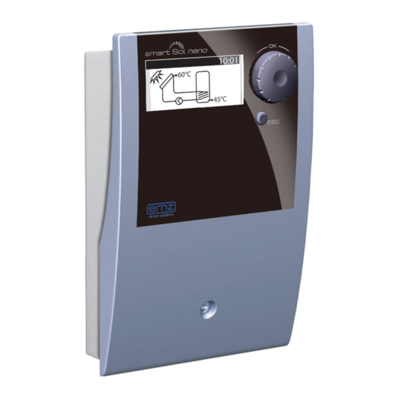
Page 6 DESCRIPTION The differential temperature controller smart Sol nano is an independent electronic controller for surface-mounting which is used for the control of solar thermal plants. The controller is equipped with a robust three-part plastic housing which can only be opened by means of tools (screw driver PH2). -
Page 7: Dimensions
DIMENSIONS Page 7 102mm 45mm 25mm 5/9mm 150mm 100mm 61mm 41mm 25mm... -
Page 8: Technical Data
The fitter explains all the relevant functions to the operator. For operation, it is essential that the housing is closed and free of damage. Scope of supplies 1 Differential temperature controller smart Sol nano 1 Instruction manual Differential temperature controller smart Sol nano... - Page 9 TECHNICAL DATA Page 9 Interfaces TS1 / TS2 / TS3 / TS4 Design 2 spring-type terminals each Inputs TS1 / TS2 / TS3 Admissible temperature sensor Pt 1000 Output TS4 PWM output Note! Description of the assignment/configuration at TS4 on page 21. Triac output RO1 Design 3 spring-type terminals each, PE, N and L...
-
Page 10: Designation Of The Components
Page 10 DESIGNATION OF THE COMPONENTS Rotary encoder with OK button Display esc button Housing cover Housing base Spare fuse Fuse Terminals Break-out segments Screw-fastening of strain relief device Strain relief device Drillhole for securing bolt Screw-fastening of terminal cover Terminal cover... -
Page 11: Operation Of The Controller
Page 11 The entire set-up and operation of the differential temperature controller smart Sol nano is effected via only two control elements on the device front. All settings and interrogations are effected via the rotary encoder. To find a required menu item, turn the rotary encoder to ›scroll‹... -
Page 12: Display
For indication of the operating mode and for communication in case of set-up, malfunction, modification and evaluation, the differential temperature controller smart Sol nano is equipped with a full graphics display which is permanently backlit. The display is active as long as there is supply voltage on the controller. -
Page 13: Opening The Terminal Cover
OPENING THE TERMINAL COVER Page 13 Danger! Mortal danger due to electrocution! Whenever work is performed on the open terminal cover, all poles of the power supply must be disconnected reliably and protected against being switched on again! Release the lock screw. Swing terminal cover forward ... -
Page 14: Wall-Mounting
Page 14 WALL-MOUNTING Important! The device corresponds to protection type IP 20 - make sure the appropriate prerequisites exist on the envisaged place of installation. Do not use the housing base as drill template. A device with damaged housing must not be operated! Fasten the top securing bolt so that a space of 2 to 3 mm is created between the wall and... -
Page 15: Connection To Power Supply
The differential temperature controller smart Sol nano is connected to the power supply via two groups of spring-type terminals which are visible once the terminal cover is opened. - Page 16 Page 16 CONNECTION TO POWER SUPPLY The strain relief device can only ensure solid clamp- ing if the cables are not stripped to a length of over 35 mm. 9-10 Insulation of the individual wires must be removed over a length of 9 - 10 mm to ensure safe electric contact in the spring-type terminal.
-
Page 17: Hydraulic Systems
If you want to complete an existing system or replace the existing controller, please make sure that smart Sol nano is compatible with the existing configuration! The sensors are connected to TS1 to TS3, PWM is connected to TS4, and the devices to be controlled are connected to RO1/REL –... - Page 18 Page 18 HYDRAULIC SYSTEM 1 Collector sensor 1 Tank 1 Tank sensor 1, bottom Solar circuit pump 1 Collector sensor 1 Connection to power supply Tank sensor 1, bottom Solar circuit pump 1...
- Page 19 Page 19 HYDRAULIC SYSTEM 2 Tank sensor 1, top Collector sensor 1 Tank 1 Tank sensor 1, bottom Solar circuit pump 1 Collector sensor 1 Connection to power supply Tank sensor 1, bottom Solar circuit pump 1 Auxiliary heating circuit Tank sensor 1, top...
- Page 20 Page 20 HYDRAULIC SYSTEM 3 Tank sensor 1, top Collector sensor 1 Tank 1 Tank sensor 1, bottom Solar circuit pump 1 Collector sensor 1 Connection to power supply Tank sensor 1, bottom Solar circuit pump 1 Tank sensor 1, top Electric heating rod supply Electric heating rod...
-
Page 21: Commissioning Mode
Commissioning is communicated in plain text; the user must make a selection, acknowledge and - if applicable - jump to the next menu item. The differential temperature controller smart Sol nano accompanies you during the entire configuration and interrogates everything it must know for optimum operation. - Page 22 Page 22 COMMISSIONING MODE 0.7 Checklist ›0.7 Checklist‹ appears. Test Outputs Here, the submenus ›Test outputs‹ and Tank 1 top ›HE output‹ are made available. HE type Select Test outputs and activate Solarpump PWM by pressing the ›OK‹ button. Note! If the ›SP 1 oben‹...
- Page 23 0.9 End You have completed ›0.9 End‹ appears. commissioning! By ›Next‹, the controller changes over to ›Automatic mode‹. Next System 1 09:10 Commissioning is complete. 60°C As of this point, the smart Sol nano controls the solar thermal plant automatically. 45°C...
-
Page 24: Automatic Mode
The pump activity is displayed 45°C on the display as animation. There is no need for intervention by the fitter or operator. Note! Check the display screen of the smart Sol nano on a regular basis to be able to eliminate any malfunctions promptly! -
Page 25: Operation Mode
OPERATION MODE Page 25 System 1 10:15 On the controller, the user can make various settings 60°C and obtain information about states and processes. To this effect, press the button ›OK‹ in automatic mode. 45°C 1 Main menu 10:16 ›1 Main menu‹ appears. Evaluation Settings A list of subitems appears... - Page 26 Page 26 OPERATION MODE ...›1.1.2 Service hours‹ appears. 1.1.2 Service h... 10:20 Solar pump 1 The operating time of the activated plant components is displayed in hours. By actuating the menu item ›Reset‹, Reset all counters are reset to zero. The values are saved once per day, so that one day max.
- Page 27 OPERATION MODE Page 27 1.2.1 Date setting 10:24 ...›1.2.1 Date settings‹ appears. Date 17.08.2012 Here, date and time can be set in case of deviation or Time 10:24 an extended period of deenergizing. Select the subitem ›Date‹ or ›Time‹ by pressing ›OK‹. 1.2.1 Date setting 10:24 One group of figures each is activated and can be var-...
- Page 28 1.3.5 dT-control 10:33 Here, parameters of the controller can be changed. dT-ON 1 8.0K The factory settings of the smart Sol nano dT-OFF 1 4.0K can be used for almost all plants. Ask a fitter before making changes at this point.
- Page 29 230V/ 60 Hz. System 1 10:41 If no entry is made within the preset time 60°C (30 - 255 s) on the smart Sol nano, the display returns to ›System‹. To return there, you can also push the button ›esc‹. 45°C...
-
Page 30: Malfunction
Service Wizard so that he/she can provide the fitter with precise information. The differential temperature controller smart Sol nano communicates malfunction processes in plain text. The Service Wizard indicates the possible causes of malfunctions on the basis of the detected symptoms and thus supports immediate and comfortable detection of deficiencies. - Page 31 MALFUNCTION Page 31 ›1.10 Service Wizard‹ appears. 1.10 Service Wi... M02: The malfunction appears in plan text - here: Breakage of sensor ›M02: Breakage of sensor on TS1!‹. on TS1! If an analysis/repair is not required at present, Menu Next press ›Menu‹...
- Page 32 Page 32 MALFUNCTION 1.10 Service Wi... Could you detect The troubleshooting result is interrogated. a short-circuit / Continue via ›Yes‹ for the case that cable break? the malfunction has been determined. 1.10 Service Wi... Repair information appears. Please replace the cable. Perform the appropriate repair work.
- Page 33 MALFUNCTION Page 33 1.10 Service Wi... Disconnect it A part of the information and instructions and measure may be provided in close detail, so that ... its resistance. Next 1.10 Service Wi... With PT1000 sensors 0°C to 100°C ...the texts... correspond to a resistance of 1.10 Service Wi...
-
Page 34: Replacement Of Fuse
Page 34 REPLACEMENT OF FUSE Danger! Mortal danger due to electrocution! Before opening the terminal cover, disconnect the power supply reliably! To remove the device fuse, open the terminal cover. Above the right-hand group of terminals, the fuse base and a spare fuse are located. Pull the upper part of the support and the spare part out. -
Page 35: Professional Mode
PROFESSIONAL MODE Page 35 Important! In professional mode, settings are made which require detailed knowledge of the heating and solar plant. Moreover, solid specialist knowledge regarding control engineering, hydraulics and solar thermal water heating is required! If a single parameter is changed, this may affect the safety, function and efficiency of the entire plant! Leave the settings in professional mode to a specialist workshop, the fitter or heating installer! - Page 36 Page 36 PROFESSIONAL MODE 1.1 Evaluation In menu item ›1.1 Evaluation‹, enhanced setting Measured values options for the operation mode are only available Service hours in subitem ›Heat quantity‹. Heat quantities Continue with ›Heat quantities‹. Message list 1.1.4 Heat quan..Here, precise settings must be made to Activation enable the controller to set up the heat...
- Page 37 PROFESSIONAL MODE Page 37 If the temperature in tank 1 exceeds the value 1.2.3 Temp.limit... ›T limit 1‹ the solar circuit pump is switched off Hyst 5.0K unconditionally. The pump is not switched on again T limit 1 60.0°C until the actual temperature falls below the value If T-limit>60°, anti-scalding ›T limit‹...
- Page 38 Page 38 PROFESSIONAL MODE 1.3.7 Output pa... Here, the general settings for the assigned outputs are defined. Solar pump 1 t-tear-off ›t tear-off‹ and ›n tear-off‹ define how long and at which speed the pumps are to run on starting. n-tear-off 100% Speed delta...
- Page 39 PROFESSIONAL MODE Page 39 Here, collector cooling can be activated: 1.3.4 Cooling fu... once the collector temperature ›T-max col1‹ Activation is reached, the solar circuit pump operates T max Coll.1 121.0°C until the tank limit temperature is reached. Return to ›1.3. Basic functions‹. Continue with ›Commissioning‹.
- Page 40 Page 40 PROFESSIONAL MODE Here, the auxiliary heating can be activated. 1.3.10 Post hea... Activation The boiler is defined as ›Immersion heater‹ or ›Gas/oil‹. Boiler type Immersion heater If ›T-charge‹ at the upper tank sensor is exceeded by ›Hysteresis‹, the control activates the auxiliary heating Ref-temp.
- Page 41 PROFESSIONAL MODE Page 41 1.5.4 Anti-legio... Repetition 1 day These parameters must be defined by the installer according to the national regulations. Use ›Function‹ to T legionellae 60.0°C define the period in days (1d - 7d) during which a le- t-ON 01:00 gionellae disinfection must have occurred at least once.
- Page 42 Page 42 PROFESSIONAL MODE ›T limit Coll. 1‹ is used to switch OFF the appropriate 1.6.4 Emerg.OFF solar circuit pumps to prevent destruction. T limit Coll.1 130.0°C Under ›Hyst‹, the value is entered by which the limit Hyst 5.0K temperature must be undercut to cancel the forced max.
- Page 43 PROFESSIONAL MODE Page 43...
-
Page 44: Disassembly/Disposal
Before opening the terminal cover, disconnect all poles of the power supply reliably! For disassembly of the differential temperature controller smart Sol nano, reverse assembly procedure: - Disconnect the power supply. - Open the terminal cover. - Disconnect all cables. -
Page 45: Warranty And Liability
WARRANTY AND LIABILITY Page 45 The differential temperature controller smart Sol nano was developed, manufactured and tested according to stringent quality and safety specifications and corresponds to the state of the art. The device is subject to the warranty period prescribed by law of 2 years after the date of sale. -
Page 46: Error Report
Page 46 ERROR REPORT Error pattern/error description: Error message: Software version: Service Wizard executed: Screens: TS1: TS2: TS3: TS4: Wiring: RO1: Pump REL: Service hours: RO1: REL: Equipment/Accessories/Options: Important! For repair or replacement of the controller, make sure that completed copies of the commissioning report and of the error report are included! -
Page 47: Commissioning Report
Tank sizes [l]: Anti-freeze agent Type/concentration: Particularities: The solar thermal plant with the differential temperature controller smart Sol nano has been installed and commissioned in an expert fashion. The owner / operator of the plant was informed in detail and instructed as regards the design, operation, handling, especially in connection with the differential temperature controller smart Sol nano. -
Page 48: Ec Declaration Of Conformity
D - 92507 Nabburg declares in its sole responsibility that the following product: Differential temperature controller smart Sol nano to which this Declaration refers, complies with the following directives and standards: Directive 2006/95/EC of the European Parliament and the Council dated 12 December 2006 on the harmonization of the laws of the Member States relating to electrical equipment designed for use within certain voltage limits. -
Page 49: Index
INDEX Page 49 Hz operation ntended Use ctive system egend to symbols Anti-blocking Login 29/35/42 Anti-legionellae Antifreeze alfunction 30 ff. Auxiliary heating 16/28/40 Manual mode Message list 26/29 oiler control functions Break-out segments 10/15 peration of the controller Output parameter able cross sections Cable diameter rofessional mode... -
Page 50: Appendix - List Of Messages
Page 50 APPENDIX – LIST OF MESSAGES Number Text on display Description of error or warning Activity No present For this message, no error was found none error found! Sensor short- Sensor short circuit at sensor input TS1 circuit on TS1! Breakage of sensor Sensor breakage at sensor input TS1 on TS1! - Page 51 APPENDIX – LIST OF MESSAGES Page 51 Number Text on display Description of error or warning Activity Invalid values were entered for the time and Check date. New values have to be entered; reason: none date and time overly long voltage interruption. yes, see in the parameter memory area, a bit error Checksum error in...
- Page 52 Edition BE 07/2016 0157 - 31RPT2S2U2G2AT3-C emz-Hanauer GmbH & Co. KGaA Siemensstraße 1 D-92507 Nabburg info@emz-hanauer.com Telephone: +49 (0) 9433 898-0 support.ht@emz-hanauer.com www.emz-hanauer.com Fax: +49 (0) 9433 898-188 www.emz-hanauer.com...
Need help?
Do you have a question about the Smart sol nano and is the answer not in the manual?
Questions and answers