Table of Contents
Advertisement
Quick Links
Advertisement
Table of Contents

Related Manuals for Dahua NVS0X04DH


Summary of Contents for Dahua NVS0X04DH
- Page 1 Network Video Decoder Quick Start Guide V3.4.0...
-
Page 2: Table Of Contents
Table of Contents FRONT PANEL/REAR PANEL/INSTALLATION ........1 Check Unpacked Device ......................1 Front panel ..........................1 1.2.1 1/4-channel 4K High Definition &1/4-channel High Definition Series ......1 1.2.2 9-channel 4K high definition (with 4 input ports) series / 9-channel 4K high definition series /9-channel High Definition Series/16-channel High Definition Series...... - Page 3 Login ............................13 2.2.1 Preparation ........................13 2.2.2 Login ........................... 14 Main Window .......................... 16...
- Page 4 Welcome Thank you for purchasing our product! This quick start guide will help you become familiar with our device in a very short time. Before installation and operation please read the following safeguard and warning carefully! Please keep it well for future reference!...
- Page 5 Important Safeguard and Warning 1.Electrical safety All installation and operation here should conform to your local electrical safety codes. The product must be grounded to reduce the risk of electric shock. We assume no liability or responsibility for all the fires or electrical shock caused by improper handling or installation.
-
Page 6: Front Panel/Rear Panel/Installation
1 Front Panel/Rear Panel/Installation Note: All the installation and operations here should conform to your local electric safety rules. VGA cable quality and length can affect the video quality. It may result in distorted video, noise, black margin. The video quality may vary even if you are viewing the same video via different VGA cables. -
Page 7: 9-Channel 4K High Definition (With 4 Input Ports) Series / 9-Channel 4K High Definition Series /9-Channel High Definition Series/16-Channel High Definition Series
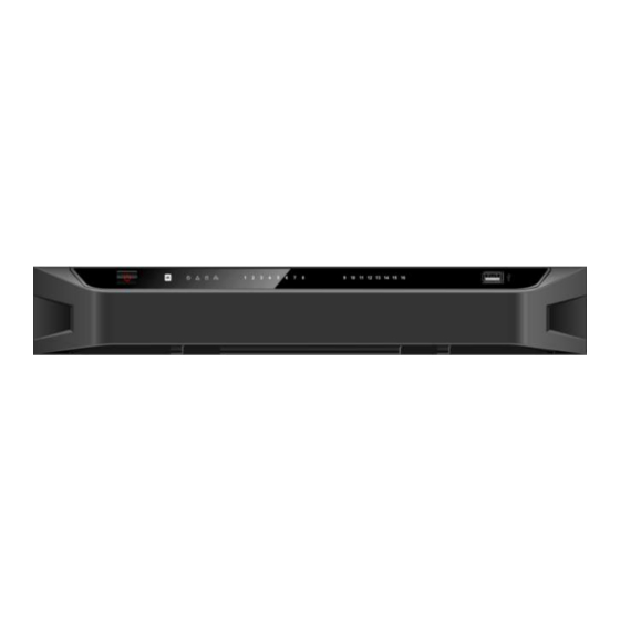
Name Icon Function Alarm indicator The light becomes on when there is an alarm. light indicator light IR receiver Output indicator It is to display output port working mode. light For 1-channel 4K high definition series and 1-channel high definition series, only the first indicator light is effective. -
Page 8: (With 4 Input Ports) Series
Name Icon Function Press it three times within one second, it can clear device configuration. Power indicator The indicator light becomes on when system boots up. light Network indicator The indicator light becomes on when abnormal light network event occurs (offline, IP conflict and etc.) USB port Connect to external USB device. -
Page 9: Rear Panel
Figure 1-4 Please refer to the following sheet for detailed information. Name Icon Function Press it for three seconds to boot up or shut down Power button the device. IR receiver Power indicator The indicator light becomes on when system light boots up. -
Page 10: 4-Channel 4K High Definition Series
Please refer to the following sheet for detailed information. Port Name Port Name Port Name Ground screw RS232 port USB port hole Network interface(10M/100M/1 HDMI port VGA port 000M self-adaptive Ethernet port) 4-channel alarm input, Audio talk output Audio talk input 4-channel alarm output, port RCA OUT port RCA IN... -
Page 11: 9-Channel 4K High Definition Series
Figure 1-7 Please refer to the following sheet for detailed information. Port Name Port Name Port Name Ground screw hole Power socket Power on-off button HDMI output port RS232 port USB3.0 port Network interface(10M/100M Audio talk input Audio talk output /1000M port port... -
Page 12: 1-Channel High Definition Series
screen port 1.3.5 1-channel High Definition Series The rear panel is shown as below. See Figure 1-9. Figure 1-9 Please refer to the following sheet for detailed information. Port Name Port Name Port Name Ground screw hole Audio output port(BNC) Video output port (BNC) Audio talk input Audio talk output... -
Page 13: 9-Channel High Definition Series
Relay input, relay Power socket Power switch output, duplex RS485 port 1.3.7 9-channel High Definition Series The rear panel is shown as below. See Figure 1-11. Figure 1-11 Please refer to the following sheet for detailed information. Port Name Port Name Port Name Ground screw hole Power switch... -
Page 14: (With 4 Input Ports) Series
Please refer to the following sheet for detailed information. Port Name Port Name Port Name Ground screw hole Power switch Power socket HDMI port (16) VGA port (16) Audio talk output port Audio output port Standard RS485 port Audio talk input port Network RS232 port interface(10M/100M/1000M... - Page 15 series rear panel is shown as below. See Figure 1-15. Figure 1-15 The 12-channel 4K high definition series/12-channel 4K high definition (with 4 input ports) series rear panel is shown as below. See Figure 1-16. Figure 1-16 Note For the above four series, they only have different decode card types. The rest parts are the same.
- Page 16 Please refer to the following sheet for detailed information. Name Name Name Main control board power indicator light, Default button system status USB port indicator light, PCI-E status indicator light HDMI output port Audio talk input port Audio talk output port ...
-
Page 17: Connection
Figure 1-20 Please refer to the following sheet for detailed information. Name Name Name DVI input port Backup button HDMI input port Indicator light Note: When you connect it to the PC network port, please use crossover cable. When you connect it to the PC via router or switcher, please use straight cable. 1.4 Connection Please refer to the follow figure for connection information. -
Page 18: Operation
2 Operation The following operations are generally based on the 9-channel high definition series product. Slight different may be found in the user interface. 2.1 Boot Up and Shut Down Boot up Connect the device to the power and then press the power button in the rear panel. You can see the power indicator light becomes on and device boots up. -
Page 19: Login
System is compatible with web control of WINVISTA. But you need to disable account control item and then reboot the PC. 2.2.2 Login Open the IE and then input the device IP address in the address column. For example, if your device IP address is 192.168.1.100, then please input http:// 192.168.1.100 in IE address column. - Page 20 Figure 2-2 After installation, the interface is shown as below. See Figure 2-3. Figure 2-3 Please input your user name and password and then click Login button. Default factory name is admin and password is admin. Note: For security reasons, please modify your password after you first login. Now you can see system pops up the following dialogue box to remind you to change the default password.
-
Page 21: Main Window
Figure 2-4 Click Yes button, you can see the Modify Password dialogue box. Please input the new password twice and then click the Yes button. See Figure 2-5. Click No button to remain the default password. Figure 2-5 2.3 Main Window After login successfully, you can go to the main interface. - Page 22 Figure 2-6 For 9-channel high definition series/16-channel high definition series, the interface is shown as in Figure 2-7. Figure 2-7...
- Page 23 For 4-channel 4K high definition series/ 9-channel 4K high definition series/9-channel 4K high definition (with 4 input ports) series, the interface is shown as Figure 2-8. Figure 2-8 For 12-channel 4K high definition series/12-channel 4K high definition (with 4 input ports) series/ 15-channel 4K high definition series/15-channel 4K high definition (with 4 input ports) series/ 18-channel 4K high definition series/18-channel 4K high definition (with 4 input ports) series/ 21-channel 4K high definition series/21-channel 4K high definition...
- Page 24 Please refer to the following sheet for detailed information. Name Name System menu Screen No. Splicing wall Bidirectional talk Connected front-end device Add/delete device list Playback Window split adjustment/screen Full-screen button manager Refresh Scheme manager/Save Roam Local signal Note: For detailed operation introduction, please refer to our resource CD included in your package for electronic version of the User’s Manual.
Need help?
Do you have a question about the NVS0X04DH and is the answer not in the manual?
Questions and answers