Table of Contents
Advertisement
Advertisement
Table of Contents

Related Manuals for geminox MERITE ZEM 2-17 C


Summary of Contents for geminox MERITE ZEM 2-17 C
- Page 1 Technical instructions Gas condensing boiler ZEM 2-17 C | ZEM 5-25 C ZEM 5-25 SEP...
-
Page 2: Table Of Contents
CONTENT - SAFETY PRECAUTIONS ........................5 - SYMBOLS.............................. 5 - SAFETY PRECAUTIONS ........................5 2.1 - Smell of gas ..........................5 2.2 - Smell of flue gas ........................5 2.3 - Explosive or inflammable materials ................... 5 2.4 - Fitting, commissioning ....................... 5 2.5 - Servicing ............................ - Page 3 CONTENT - POSITION OF THE BOILER ....................... 21 3.1 - Rear wall spacer / fitting dimensions ..................21 - DISASSEMBLING THE COVER......................21 - COMBUSTION PRODUCT FLUEING ....................22 5.1 - The boiler flue tube positioning ....................22 5.2 - Evacuation by chimney flue (B23/C93) ................... 23 5.3 - Adaptor C93 ..........................
- Page 4 CONTENT VIII - GAS CONVERSION ..........................47 - GAS CHANGE ............................. 47 1.1 - Conversion from natural gas to propane (option) ..............47 - GAS/CO2/CO/NOX FLOW CONTROL AND SERVICE PRESSURE CONTROL ....... 48 2.1 - Surveillance procedure ......................49 2.2 - Setting table ..........................50 IX - MAINTENANCE ..........................
-
Page 5: I - Safety Precautions
I - SAFETY PRECAUTIONS 1 - SYMBOLS In this document: Safety recommendations, warnings triangle symbol accompanied by bold text. and recommendations are by a warning- 2 - SAFETY PRECAUTIONS - B23 Chimney type system: 2.1 - Smell of gas • Ventilation openings in doors, windows and walls must not be sealed or restricted. - Page 6 SAFETY PRECAUTIONS - This appliance must only be operated by a res- ponsible adult who has been instructed in, un- derstands, and is aware of the appliance's operating conditions and effects. - Children should be supervised to ensure they do not play with the appliance.
-
Page 7: Presentation
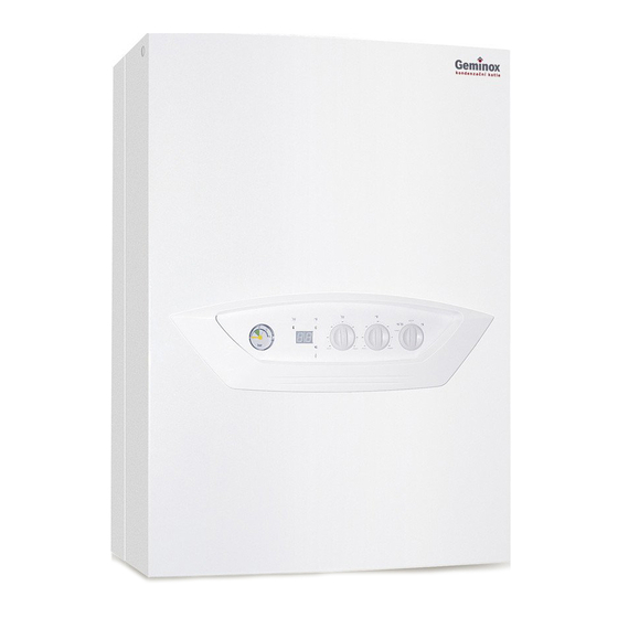
II - PRESENTATION 1 - DESCRIPTION Standard description: wall mounted condensing - a 3 bar safety-valve, boiler for hot water heating, sealed combustion cir- - a rear wall spacer, cuit, pre-mixing burner with air-gas supply, and OPTIONS: linear power modulation connecting combustion - A rear spacer allowing for the hydraulic connec- product types B following EN 483... -
Page 8: Technical Specifications
III - TECHNICAL SPECIFICATIONS 1 - CHARACTERISTICS Models ZEM 2-17 C ZEM 5-25 C ZEM 5-25 SEP CE1312BR4644 CE1312BR4313 Certification Category / Country of destination: GB/IE II2H3P eat output (Heating) 30/50 °C 2.7/18.8 5.6/27.4 60/80 °C 2.3/17.3 5.0/25.2 Heat input (Heating) 2.5/17.6 5.2/25.6 Heat input (Domestic hot water) -
Page 9: Contribution Of The Temperature Control To Seasonal Space Heating Efficiency
TECHNICAL SPECIFICATIONS Models ZEM 2-17 C ZEM 5-25 C ZEM 5-25 SEP Max.total power consumption Absorbed electrical power in heating mode Control alone (= Electrical power consumption of the minimum load: 13 auxiliaries) maximum load: 34 Circulating pump speed 1 (4 m) Circulating pump speed 2 (5 m) -
Page 10: Dimensions
TECHNICAL SPECIFICATIONS 4 - DIMENSIONS 4.1 - ZEM 2-17 C / ZEM 5-25 C 4.2 - ZEM 5-25 SEP Fig. 1 Fig. 2 Bottom view Bottom view 80.4 80.4 Front view Front view Top view Top view mini mini mini mini Legend: a: Combustion products outlet... -
Page 11: List Of Components
TECHNICAL SPECIFICATIONS 5 - LIST OF COMPONENTS 5.1 - ZEM 2-17C / ZEM 5-25 C Fig. 3 1) Gas inlet 16) Air bleed 2) Gas valve (solenoids and regulator) 230 V 17) Silencer 3) Gas burner 18) Drain tap 4) Combustion products outlet (flue) 19) Safety valve 3 bar 5) Flue gas sensor 20) Safety valve outlet... -
Page 12: Zem 5-25 Sep
TECHNICAL SPECIFICATIONS 5.2 - ZEM 5-25 SEP Fig. 4 1) Gas inlet 17) Silencer 2) Gas valve (solenoids and regulator) 230 V 18) Drain tap 3) Gas burner 19) Safety valve 3 bar 4) Combustion products outlet (flue) 20) Safety valve outlet 5) Flue gas sensor 21) Siphon trap 6) Heating flow... -
Page 13: Circulating Pump Characteristics
TECHNICAL SPECIFICATIONS 6 - CIRCULATING PUMP CHARACTERISTICS The boiler features a UPM3 FLEX AS 15-75 CIAO2 AZJ low-energy pump (high efficiency pump: Fig. 5 EEI < 0.20). The pump's maximum head can be adjusted directly via the key on the pump. The following table shows a list of possible settings. -
Page 14: For Models Zem 5-25 Sep
TECHNICAL SPECIFICATIONS 6.1 - For models ZEM 5-25 SEP To ensure the domestic hot water performances, set the heating circulator to the 3rd speed (i.e. 6 m head - refer to section 6 - page 13). 7 - AVAILABLE PRESSURES Fig. -
Page 15: Expansion Vessel Characteristics
TECHNICAL SPECIFICATIONS 8 - EXPANSION VESSEL CHARACTERISTICS Merite boilers are pre-equipped with an expansion vessel for an installation water capacity of approxi- Fig. 9 mately 80 litres (section 6.2 - page 32 - chapter V - INSTALLATION). The expansion vessel absorbs the increase in the water volume in the installation produced by the in- crease in temperature. -
Page 16: Operation
IV - OPERATION 1 - GENERAL OPERATING PRINCIPLE The Merite boilers combine a fully stainless steel Characteristics of the ZEM SEP boiler: boiler shell, guarantee of longevity, and a premixing - To avoid the problems of in inertia and immedia- burner with proven technology and efficiency. -
Page 17: Safety Test And Regulator Shutdown Function
OPERATION 2.5.2 - Regulator shutdown button 2.5 - Safety test and regulator shutdown The regulator shutdown function enables the com- function bustion tests to be carried out by operating the boiler The purpose of the safety test function is to bring the at the maximum hot water power then at the mini- boiler to maximum heating power and subsequently mum hot water power using the heating setting but-... -
Page 18: Info" Function: Displaying Parameters On The Boiler Display
OPERATION • A0: Domestic hot water temperature (°C) 2.6 - “INFO” function: displaying • A1: Outside temperature (°C) parameters on the boiler display • A2: PWM signal of the fan (%) The “INFO” function is used to display some of the •... -
Page 19: Installation
V - INSTALLATION 1 - GENERAL Installing a wall-mounted gas boiler presents no par- An existing cupboard or compartment may be used ticular difficulty. provided it is modified for the purpose. Details of es- sential features of cupboard/compartment design, The installation of the boiler must be carried out by including airing cupboard installations, are given in a competent person in accordance with the relevant BS.6798. -
Page 20: Ventilation
INSTALLATION WATER CIRCULATION SYSTEM bore systems - BS.5449.1. The domestic hot water system, if applicable, should be in accordance with The expansion vessel is suitable for systems up to the relevant recommendations of BS.5546. 80 litres water content. For systems in excess of this capacity an additional pressurised expansion Copper tubing, to BS. -
Page 21: Position Of The Boiler
INSTALLATION 3 - POSITION OF THE BOILER Define the location of the boiler by taking into ac- count various conditions: environment, accesses to the boiler, etc. 3.1 - Rear wall spacer / fitting dimensions Fig. 12 Bottom view Top view ZEM .. -
Page 22: Combustion Product Flueing
INSTALLATION 5 - COMBUSTION PRODUCT FLUEING The combustion product outlet systems • Ensure that sealing joints have described in this manual are systems been fitted. normally used on the European market. • Use fastening collars (supplied as However, some of them cannot be used an option) or clamps to solidly se- in all the countries of the EEC. -
Page 23: Evacuation By Chimney Flue (B23/C93)
INSTALLATION 5.3 - Adaptor C 5.2 - Evacuation by chimney flue Adaptor used to connect a Ø 80/125 sealed connec- tion of type C An existing chimney flue can be used provided that it is cleaned before the See kit assembly guide for the part. lining is fitted. - Page 24 INSTALLATION 5.3.1 - Configuration with pressurized lining 5.3.1.1 - Installation example (B Fig. 17 Definition : Lining of an existing chimney flue by a corrugated PP flue conduit of Ø 80 according to the height. - The termination, specific to this configuration and specified in the DTA, must have its outlet above the roof (comply with the specification of the de- cree of 22 October 1969),...
- Page 25 INSTALLATION 5.3.2 - Sealed configuration (C 5.3.2.1 - Installation example (C ) in a chim- Definition: Lining of an existing chimney flue, sea- led with respect to the installation room by a PP cor- rugated flue of Ø 80 (in this case the air inlet is obtained by the chimney flue around the combus- Fig.
-
Page 26: Balanced Flue Outlet (C13/C33)
INSTALLATION 5.4 - Balanced flue outlet (C 5.4.1 - Balanced flue system installation requi- Combustion product extraction outlets that open rements: out directly onto an outside route (public or pri- vate road) less than 1.80m from the ground, ex- The three statutory clearance distances accor- cept for condensation installations, must have a ding to the installation standards are: fixed defector that redirects discharged gas more... - Page 27 INSTALLATION Air intake by the burner and extraction 5.4.2.1 - PP/PVC 0,83 m horizontal balanced of combustion product is carried out- flue kit (optional) side the premises by using concentric See kit assembly guide tubes. Fig. 20 5.4.2 - Drainage by horizontal balanced flue Distributor recommendations Horizontal balanced flue installation is possible when the wall next to the boiler...
- Page 28 INSTALLATION 5.4.2.4 - Installation examples Fig. 25 Please refer to the guide when installing the kit. Note: - For lengths greater than 0.83 m (standard hori- zontal flue kit) use the extensions and bends sup- plied as an option. Lmax ≤ 8 m 5.4.2.4.1 - Straight horizontal balanced flue Fig.
- Page 29 INSTALLATION 5.4.2.4.3 - Straight horizontal balanced flue with 5.4.3 - Extraction by vertical balanced flue collar Besides the previously mentioned installation regu- Fig. 27 lations pertaining to flues, the vertical flue terminal must allow a minimum distance of 30 cm between the roof level (sloping or flat) and the air intake zone.
- Page 30 INSTALLATION 5.4.3.2 - Sleeve tile with adaptive coupling Each 45° bend added reduces the total permitted (option) length by 0.5m. Each 90° bend added reduces the total permitted Fig. 30 length by 1m. 5.4.3.5 - Polypropylene roof plate (option) AM5-22-0 Fig.
- Page 31 INSTALLATION 5.4.3.8 - Examples of installation 5.4.3.8.2 - Configuration with bends 5.4.3.8.1 - Straight configuration Avoid fitting 90° bends for this configu- ration. Fig. 36 If fitting 90° bends can be avoided: - never use more than 2, - maintain a slope to the boiler for the horizontal section.
-
Page 32: Hydraulic Connection
INSTALLATION 6 - HYDRAULIC CONNECTION 6.1 - Distributor recommendations When the boiler is assembled on an old ageing the seals and the domestic hot water sys- installation, make sure that the installa- tem itself, please ensure the following: tion is rinsed with fresh water, so as to •... -
Page 33: Hydraulic Connection For Models Zem 2-17 C And Zem 5-25 C
INSTALLATION Example: • Calculation of the useful capacity of the vessel (Cu): • Installation: 100 litres • Domestic hot water tank: 5 litres × volume total expansion • Boiler: 2.7 litres • Total water capacity: 107.7 litres 107 7 , 0 06 ×... -
Page 34: Hydraulic Connection For Models Zem C + Dhw Production System Of Type Bs With Internal Selector Valve Kit
INSTALLATION 6.4 - Hydraulic connection for models ZEM C + DHW production system of type BS with internal selector valve kit Fig. 39 1) Gas inlet 2) Gas cock 3) Boiler 4) Radiator* 5) Heating flow isolation valve 6) Heating flow 7) Heating return isolation valve 8) Heating return 9) Cold water inlet... -
Page 35: Hydraulic Connection For Models Zem 5-25 Sep
INSTALLATION 6.6 - Hydraulic connection for models ZEM 5-25 SEP Fig. 41 1) Gas inlet 2) Gas cock 3) Boiler 4) Radiator* 5) Heating flow isolation valve 6) Heating flow 7) Heating return isolation valve 8) Heating return 9) Cold water inlet 10) Domestic cold water inlet 11) Removable filling loop with filling valve 12) Isolation valve*... -
Page 36: Electrical Connection
INSTALLATION 8 - ELECTRICAL CONNECTION - The electrical connection and all the equipment used to make this connection must be in confor- Fig. 42 mity with the codes of practise in force (according 230 V to the installation standards), 50Hz - the premises must be suitable in terms of boiler protection IP 44 (model C ) - IP 24 (model... -
Page 37: Reg 60/Reg 151 Room Thermostat (Option)
INSTALLATION 8.3.2 - REG 151 8.3 - REG 60/REG 151 room thermostat Fig. 43 (option) When the room thermostat is not the one recom- mended by the distributor, Check the characteris- tics: • 230V, 5 mA, • max. capacitance between the live and the thermostat input: Cp<4000pF. -
Page 38: Wiring Diagram
INSTALLATION 8.4 - Wiring diagram Fig. 45 1) Power supply 230 V - 50 Hz 13) Outside sensor 2) Mode selector (Reset/Winter/Off/Summer) 14) Ionization electrode 3) Fan 230 V~ 15) Ignition electrode 4) Ignition transformer 230 V~ 16) Shunt to be removed for room thermostat or room sensor (QAA53/QAA73) connection 5) Gas valve 230 V~ 17) Removable fuse... -
Page 39: Parameters
VI - PARAMETERS 1 - PARAMETER LIST 1.1 - Parameters available for possible adjustment Factory setting: boiler version Line Display Function Range 2-17 C 5-25 C 5-25 SEP 501 TrSollMin Minimum room temperautre setpoint 5...20°C 17°C 17°C 17°C 502 TrSollMax Maximum room temperautre setpoint 20...35°C 23°C... -
Page 40: Access The Settings Via The Qaa 73 Room Sensor
PARAMETERS Line Display Function Unit 752 Status_Ausgang1 Status output signals LMU 752.0 Heating pump on = 1; pump off = 0 752.1 3-way valve for heating = 1; 3-way valve for DHW = 0 2 - ACCESS THE SETTINGS VIA THE QAA 73 ROOM SENSOR When switched on: - CLOW appears on the display or after a pro- longed period out of service. - Page 41 PARAMETERS Touche Remarque By pressing the line selection button, choose the required operating level. (USR = End-user/ INST = Heating engineer / OEM = OEM) Display : INST Press the OK button to confirm your choice - The number of the parameter line and its value are successively displayed. Display : °C °C...
-
Page 42: Commissioning
Its compliance with standards and instructions remains the exclu- sive responsibility of the installation company. Geminox insists the use of the following heating system water conditioning products: - BIONIBAL corrosion inhibitor (or equivalent products), - BIONIBAGEL antifreeze and corrosion inhibitor (or equivalent products). -
Page 43: Filling The Installation With Water
COMMISSIONING 2 - FILLING THE INSTALLATION WITH WATER - The installation will have to be rinsed before the . Open the heating flow/return isolation boiler is filled with water. valves, - To ensure proper boiler bleeding during the ins- . Open the cold water inlet valve, tallation’s filling stage: . -
Page 44: Setting The Maximum Power In Heating Mode
COMMISSIONING 5 - SETTING THE MAXIMUM POWER IN HEATING MODE The maximum power of the boiler in heating mode page 40 - chapter VI - PARAMETERS. can be limited. This operation requires modification The NHz value should be selected by following the of the NHz parameter in the boiler's LMU manage- diagram below. -
Page 45: Commissioning
COMMISSIONING 8 - COMMISSIONING Fig. 47 ZEM-21-0 1) Mode selector: used to access 4 operating 2) Domestic hot water temperature adjustment modes simply by turning the button 3) Heating temperature mode • RESET: hold the button for at least 1 se- 4) Flame presence indicator light: cond in this position then release it to re- burner operating - LED (4) on... -
Page 46: Faults During Operation
COMMISSIONING In summer mode: Stop the heating 8.3 - Faults during operation mode by pressing the heating circuit operation button on the room sensor If a problem occurs: (QAA 53/QAA73). : stand-by. • a fault code appears on the display (item 7) . -
Page 47: Gas Conversion
VIII - GAS CONVERSION Check that the boiler is properly adapted to the gas used, otherwise change the gas. 1 - GAS CHANGE This operation must be carried out by (G20), 20 mbar. a qualified person equipped with a ca- When changing the gas, the “gas setting”... -
Page 48: Gas/Co2/Co/Nox Flow Control And Service Pressure Control
GAS CONVERSION 2 - GAS/CO /CO/NO FLOW CONTROL AND SERVICE PRESSURE CONTROL Fig. 50 = Network gas pressure Natural gas H (G20): 20 mbar, GAS VALVE Propane (G31): 37 mbar. SIEMENS/LANDIS = Outlet gas pressure to the burner. ref: VGU87A0236 PL = Air pressure control (Fan-Gas valve) V = Adjust the slope of the characteristic of the air/gas ratio only when the burner is at high rate. -
Page 49: Surveillance Procedure
GAS CONVERSION - return to normal operation by deactivating the re- Fig. 51 gulator shutdown function (refer to section 2.5.3 - Chimney flue page 17 - chapter IV - OPERATION). Note: - Remember to reposition the d.h.w. setting button to return to the required d.h.w. setting chosen by ZEM-36-0 the customer. -
Page 50: Setting Table
GAS CONVERSION 2.2 - Setting table Models ZEM 2-17 C ZEM 5-25 Heat output (Heating) 30/50 °C 2.7/18,8 5.6/27.4 2.3/17.3 5.0/25.2 60/80 °C Heat input Heating Heating 2.5/17.6 5.2/25.6 5.2/29.0 ∅ Gas reducer Nat Gas H 4.20 6.20 Propane 4.65 ∅... -
Page 51: Maintenance
IX - MAINTENANCE The annual inspection of the boiler and of the com- Remove the front panel (item G) from bustion product outlet is compulsory and validates the boiler and disconnect the earth wire warranty. It must be carried out by a qualified per- (item O). - Page 52 MAINTENANCE Disassembling the burner/fan unit: Cleaning the burner: - Disconnect the electrical connections of the bur- - Clean the burner (item 3) using a domestic va- ner/fan unit: cuum cleaner by placing the suction device over the air inlet and the gas inlet successively, •...
-
Page 53: Servicing The Heat Exchanger Of The Boiler Shell
MAINTENANCE 2 - SERVICING THE HEAT EXCHANGER OF THE BOILER SHELL The heat exchanger must be cleaned once the bur- - refit the burner to the boiler shell, ner has been disassembled (section 1 - page 51 - • check the correct positioning of the sealing chapter IX - MAINTENANCE). -
Page 54: Expansion Vessel Pre-Inflation Pressure Check
MAINTENANCE 5 - EXPANSION VESSEL PRE-INFLATION PRESSURE CHECK - Drop the pressure in the heating installation by • adjust its pre-inflation pressure in line with the opening the drain cock or the safety valve (pres- installation. It must correspond to the static sure gauge reading under 0.5 bar). -
Page 55: Draining
MAINTENANCE 8 - DRAINING - Cut the power supply, Fig. 55 - turn off the gas cock, - turn off the heating flow/return valves (if they are fitted), - connect the drain valve (item. 18) to the sewage system, - open the drain valve. Ensure that the air bleed (item. -
Page 56: Operating Faults
X - OPERATING FAULTS 1 - OPERATING FAULTS LIST (BOILER) Display A0 Description Solution Outside sensor fault Check that the sensor is correctly fitted and connected Boiler sensor fault Check that the sensor is correctly fitted and connected Flue gas detector fault Check that the sensor is correctly fitted and connected Flow sensor 1 fault... -
Page 57: Operating Faults List For Pump
OPERATING FAULTS 2 - OPERATING FAULTS LIST FOR PUMP Prior to any work on the pump, it must be disconnected from the power sup- ply. Remember that capacitors can still be charged up to 30 seconds following disconnection from the power supply. LED display Cause Pump state... -
Page 58: Options
XI - OPTIONS 1 - REGULATION OF ROOM TEMPERATURE 1.1 - Room thermostat (REG 60) 1.3 - QAA 53 room sensor The QAA53 is a digital room sensor with a daily pro- The Room thermostat is a room thermostat with a gramme for controlling a heating system. -
Page 59: Selector Valve Kit For Connecting Zem
OPTIONS 2 - SELECTOR VALVE KIT FOR CONNECTING ZEM..C/BS The selector valve kit allows the connection of a Fig. 60 central heating only type boiler to a domestic hot water heater. Refer to kit installation instructions. 3 - EXTERNAL SELECTOR VALVE KIT FOR CONNECTING ZEM..C/BS The external selector valve kit allows the connection Fig. -
Page 60: Bs Type Domestic Hot Water Production System
OPTIONS 5 - BS TYPE DOMESTIC HOT WATER PRODUCTION SYSTEM BS domestic hot water production systems can pro- Fig. 63 duce hot water when the installation contains a boi- ler that only operates for heating. The capacity of the BS systems varies with the mo- del chosen. -
Page 61: Warranty
XII - WARRANTY All ZEM Merite boilers come from the manufacturer, Geminox France, with a 5-year warranty on the heat ex- changer and 5 years on the burner. All other parts are covered by a 2-year parts warranty. All replacement parts are covered by a further 1-year parts warranty. - Page 62 - damage which may result from use of the equipment with a fuel other than that stated in the manual - ionising electrodes, ignition electrodes. Your Geminox appliance is one of the most reliable and technically advanced products available. However, it is imperative that it is installed correctly, validated and serviced in accordance with Geminox installation and servicing manuals to ensure long life, reliability and fuel savings.
- Page 63 For the UK contact: Gemtex Heating Solutions Limited Aviation Park Enterprise Way Christchurch BH23 6NX Call: 01256 587800 Mail: info@gemtex.co.uk Web: www.gemtex.co.uk Company no. 10617497...
Need help?
Do you have a question about the MERITE ZEM 2-17 C and is the answer not in the manual?
Questions and answers