Table of Contents
Advertisement
Quick Links
This manual contains text, diagrams and explanations which will guide the user in the correct installation
and operation of the FX
to install or use the unit. Further information can be found in the FX PROGRAMMING MANUAL(ΙΙ), FX
/FX
/FX
/FX
SERIES HARDWARE MANUAL.
1N
2N
2NC
1. Introduction
•
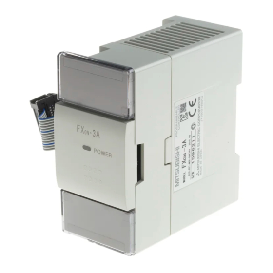
The FX
-3A analog special function block has two input channels and one output channel.
0N
The input channels receive analog signals and convert them into digital values.
The output channel takes a digital value and outputs an equivalent analog signal.
The FX
-3A has a maximum resolution of 8 bits.
0N
•
The selection of voltage or current based input/output is decided by user wiring.
•
An FX
-3A can connected to the FX
0N
(Hereafter referred to as a PLC).
•
All data transfers and parameter setups are adjusted through software control for the FX
TO/FROM applied instructions in the PLC. Communications between the PLC and FX
protected by a photo-coupler.
•
An FX
-3A occupies 8 I/O points on the PLC's expansion bus. The 8 I/O points can be allocated from
0N
either inputs or outputs.
1.1 External Dimensions
3 5 m m
D I N r a i l
g r o o v e
2. Terminal layouts and wiring
C H 1
C u r r e n t
i n p u t
C H 2
C H 1
V o l t a g e
* 2
i n p u t
C H 2
•
When a current input is used, ensure that the terminals marked [VIN*1] and [IIN*1] are linked.
Do not connect the [VOUT] and [IOUT] terminals when the current output is used.
*1 terminal number 1 or 2 is identified here.
•
If any voltage ripple is experienced on the voltage inputs/outputs or if there is excessive electrical
noise, connect a capacitor of 0.1 to 0.47μF,
-3A special function block and should be read and understood before attempting
0N
2N
Mass: Approx. 0.2kg (0.44lbs)
9 ( 0 . 3 5 )
8 7 ( 3 . 4 3 )
+
+
+
+
Industrial automation
Elincom Group
European Union: www.elinco.eu
Russia: www.elinc.ru
FX
-3A SPECIAL FUNCTION BLOCK
0N
USER'S GUIDE
, FX
, FX
or FX
2NC
1N
0N
E x t e n s i o n
c a b l e
P O W E R
M o u n t i n g h o l e ,
2 h o l e s 4 . 5
( 0 . 1 8 ) d i a
4 ( 0 . 1 6 )
4 3 ( 1 . 6 9 )
approx.
25V rating at position *2.
JY992D49001F
series of Programmable Controllers
Dimensions: mm (inches)
A / D
O F F S E T
P O W E R
A / D
G A I N
D / A
O F F S E T
D / A
G A I N
M 3 ( 0 . 1 2 )
t e r m i n a l s c r e w s
+
* 2
+
0N
-3A, via
0N
-3A are
0N
V o l t a g e
o u t p u t
C u r r e n t
o u t p u t
Advertisement
Table of Contents

Related Manuals for Mitsubishi Electric MELSEC-F FX0N-3A


Summary of Contents for Mitsubishi Electric MELSEC-F FX0N-3A
- Page 1 Industrial automation Elincom Group European Union: www.elinco.eu Russia: www.elinc.ru -3A SPECIAL FUNCTION BLOCK USER’S GUIDE JY992D49001F This manual contains text, diagrams and explanations which will guide the user in the correct installation and operation of the FX -3A special function block and should be read and understood before attempting to install or use the unit.
- Page 2 3. Connection with PLC 1) Up to 4 FX -3A units can connect to the FX series PLC, up to 5 for FX up to 8 for FX or, up to 4 for an FX series PLC, all with powered extension units. However the following limitation exists when the undermentioned special function blocks are con- nected.
- Page 3 Voltage output Current output At shipment, 0 to 250 range selected for 0 to 10V DC output. When using an FX -3A for current output or differing voltage output except 0 to 10V DC, it is necessary to readjust the offset and gain. Analog output range DC 0 to 10V, 0 to 5V external load: 4 to 20mA, external load: 500Ω...
- Page 4 7. Change and adjustment method of input/output characteristic 7.1 Change in input/output characteristic At shipment, 0 to 250 range selected for 0 to 10V DC input/output. When using an FX -3A for current input/output or differing voltage input/output except 0 to 10V DC, it is necessary to readjust the offset and gain.
- Page 5 7.3 Method of Calibration(D/A) Use the following program and the appropriate wiring configuration to calibrate the output channel of the GAIN GAIN OFFSET OFFSET Voltage Current GAIN GAIN output output Voltmeter Ammeter 7.3.1 Output Calibration Program K16 K250 K1 K17 H04 K17 H04 K17 H00 K17 H00...
- Page 6 • All examples and diagrams shown in this manual are intended only as an aid to understanding the text, not to guarantee operation. Mitsubishi Electric will accept no responsibility for actual use of the product based on these illustrative examples.
- Page 7 3. Connection with PLC Voltage output Current output At shipment, 0 to 250 range selected for 0 to 10V DC output. 1) Up to 4 FX -3A units can connect to the FX series PLC, up to 5 for FX up to 8 for FX or, up to When using an FX...
- Page 8 All examples and diagrams shown in this manual are intended only as an aid to understanding table below) using the selected generator or analog output. the text, not to guarantee operation. Mitsubishi Electric will accept no responsibility for actual The buffer memories (BFM) of the FX -3A are written TO or read FROM by the host PLC.
Need help?
Do you have a question about the MELSEC-F FX0N-3A and is the answer not in the manual?
Questions and answers