Table of Contents
Advertisement
Quick Links
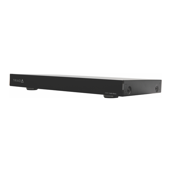
TRIAD INSTALLATION GUIDE - 8×8 and 24×24 AUDIO MATRIX SWITCH
INTRODUCTION
The Triad 8×8 and 24×24 Audio Matrix Switches enable up to 8 (or 24)
stereo audio sources to simultaneously play to 8 (or 24) audio outputs.
Each output zone can be adjusted with independent gain, bass, treble,
EQ, balance, loudness and mono summing controls. Triad Audio Matrix
Switches are ideal for use with Control4 EA Series Entertainment and
Automation Controllers, delivering dependable, high-resolution audio
distribution throughout the home.
SUPPORTED MODELS
• TS-AMS8 Triad 8×8 Audio Matrix Switch
• TS-AMS24 Triad 24×24 Audio Matrix Switch
BOX CONTENTS
• Audio Matrix Switch
• IEC power cord
• Two rack-mount ears
FEATURES
• Send up to 8 (or 24) audio sources to as many as 8 (or 24) audio zones
for reliable multi-room audio distribution
• Simple device discovery protocol (SDDP) ensures seamless integration
with Control4
• Analog and digital audio inputs support audio resolutions up to
192 kHz/24 bit
• High signal-to-noise ratio delivers dynamic, high-resolution audio to
every room in the house
• Smooth volume control (1/2 db volume steps) with real time volume
and mute status on Control4 navigators
• Independent volume, bass, treble, 5-band parametric EQ, balance,
loudness and mono summing for each output
• Independent input gain for each source input provides consistent levels
when switching between sources
• 12V trigger outputs enable simple on/off control of Triad Power
Amplifiers or other devices that support 12V power on capabilities.
• 2.1 option enables two stereo outputs to be grouped together to create
a dynamic 2.1 (sat/sub) audio zone
• Audio sensing supports programmable events based on the presence of
audio
• Ethernet control
• Rack-mount ears included
www.control4.com | 1-888-400-4072 | DOC-00287-A 2017-08-28 DH
WARNINGS
WARNING! To reduce the risk of electrical shock, do not expose this
apparatus to rain or moisture.
AVERTISSEMENT ! Pour réduire le risque de choc électrique,
n'exposez pas cet appareil à la pluie ou à l'humidité.
WARNING! Do not expose the apparatus to dripping or splashing.
Do not place objects filled with liquids near the apparatus.
AVERTISSEMENT ! N'exposez pas l'appareil à l'égoutture ou à
l'éclaboussement. Ne placez pas les objets remplis de liquides près
de l'appareil.
IMPORTANT! Using this product in a manner other than outlined
in this document voids your warranty. Further, Control4 is not
liable for any damage incurred with the misuse of this product. See
IMPORTANT ! Employer ce produit en quelque sorte autre que
décrit dans ce document vide votre garantie. De plus, Control4
n'est pas responsable d'aucun dommage encouru avec l'abus de ce
produit. Voyez que « Warranty. »
IMPORTANT! To avoid generating excessive heat, do not stack
amplifiers on top of each other or other equipment.
IMPORTANT ! Pour éviter de produire de la chaleur excessive,
n'empilez pas les amplificateurs sur l'un l'autre ou tout autre
équipement.
FRONT AND REAR PANEL DESCRIPTION
FRONT PANEL (8×8 and 24×24)
A Status LED—RGB LED to show system status. See "LED Troubleshooting
Guide" in this document for more information.
B Power LED—LED shows solid blue when matrix switch is powered on.
BACK PANEL (8×8)
A
B
C
E
D
A Power plug port—For standard IEC cord (included). Supports universal
AC input (100-240VAC, 50-60Hz).
B ETHERNET—RJ-45 port for a 10/100/1000BaseT Ethernet connection.
C FACTORY RESTORE button—Resets the device to factory default
settings.
D ID button—Identifies the device to the Control4 system.
E 12V OUTPUT TRIGGERS—3.5mm ports that output 12V for on/off control
of amplifiers. The 1-8 trigger outputs 12V whenever any output (1-8) is
active. The ASG trigger output is assignable in Composer to output 12V
whenever designated audio output(s) are active.
F ANALOG AUDIO INPUTS (1-8)—Stereo RCA jacks for up to 8 analog
audio sources.
G DIGITAL AUDIO INPUTS (5-8)—Digital coax and toslink (S/PDIF)
connectors for up to 4 digital audio sources. Inputs 5-8 can be either
digital or analog, but not both. Digital inputs do not support multi-
channel audio. Digital sources must be stereo PCM.
H ANALOG AUDIO OUTPUTS (1-8)—RCA jacks for line level output. Every
output can play audio from any input.
BACK PANEL (24×24)
A B
C
D E
A Power plug port—For standard IEC cord (included). Supports universal
AC input (100-240VAC, 50-60Hz).
B 12V OUTPUT TRIGGERS—3.5mm ports that output 12V for on/off control
of amplifiers. The 1-8 trigger outputs 12V whenever any output (1-8) is
active. The 9-16 trigger outputs 12V whenever any output (9-16) is active.
The 17-24 trigger outputs 12V whenever any output (17-24) is active. The
ASG trigger output is assignable in Composer to output 12V whenever
designated audio output(s) are active.
C ETHERNET—RJ-45 port for a 10/100/1000BaseT Ethernet connection.
D FACTORY RESTORE button—Resets the device to factory default
settings.
E ID button—Identifies the device to the Control4 system.
A
B
F ANALOG AUDIO INPUTS (1-16)—RCA jacks for stereo channel input for
up to 16 stereo analog sources.
G DIGITAL AUDIO INPUTS (17-24)—Digital coax and toslink (S/PDIF)
connectors for digital audio sources. Digital inputs do not support multi-
channel audio. Digital sources must be stereo PCM.
H ANALOG AUDIO OUTPUTS—RCA jacks for line level output. Every
output can play audio from any input.
INSTALLING THE MATRIX SWITCH
F
H
G
F
H
G
Advertisement
Table of Contents

Related Manuals for Control 4 Triad 8x8 AMS


Summary of Contents for Control 4 Triad 8x8 AMS
- Page 1 TRIAD INSTALLATION GUIDE - 8×8 and 24×24 AUDIO MATRIX SWITCH INTRODUCTION WARNINGS BACK PANEL (8×8) The Triad 8×8 and 24×24 Audio Matrix Switches enable up to 8 (or 24) WARNING! To reduce the risk of electrical shock, do not expose this stereo audio sources to simultaneously play to 8 (or 24) audio outputs.
- Page 2 TRIAD INSTALLATION GUIDE - 8×8 and 24×24 AUDIO MATRIX SWITCH INSTALLING THE MATRIX SWITCH IN A RACK CONNECTING AUDIO TO THE MATRIX SWITCH ADDING A SUBWOOFER TO A ZONE USING THE 2.1 ZONE FEATURE 1 Align the holes on the rack ears with the holes on both sides of the Physical and programming connections are required to control, navigate, matrix switch.
- Page 3 TRIAD INSTALLATION GUIDE - 8×8 and 24×24 AUDIO MATRIX SWITCH EA-5 1/ 3 IN 1 OUT 1 ETHERNET IN SERIAL 1 AC POWER: WIFI 1 WIFI 2 FACTORY 2/ 4 100-240 V~ SERIAL 2 IN 2 OUT 2 IN 1 IN 2 OUT 1 OUT 2...
- Page 4 TRIAD INSTALLATION GUIDE - 8×8 and 24×24 AUDIO MATRIX SWITCH TROUBLESHOOTING SPECIFICATIONS ADDING A 10×10 HDMI SWITCH TO A 24 SOURCE, 24 ZONE SYSTEM RESETTING THE MATRIX SWITCH AUDIO SPECIFICATIONS You can add audio from your HDMI sources to your 24-zone distributed <0.005 %, 20 Hz –...
Need help?
Do you have a question about the Triad 8x8 AMS and is the answer not in the manual?
Questions and answers