Table of Contents
Advertisement
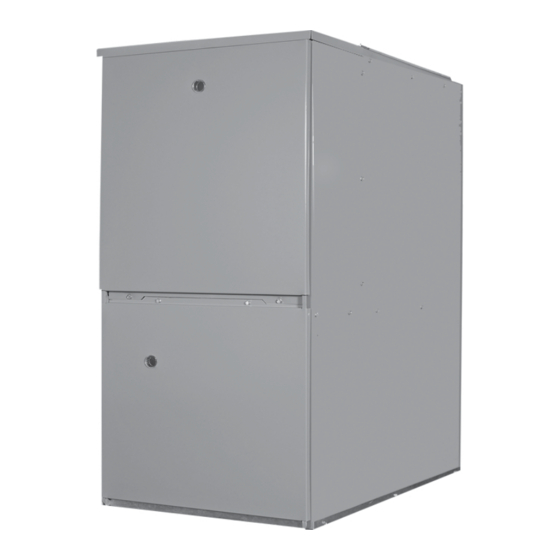
G95V
NATURAL AND PROPANE GAS TWO
STAGE HIGH EFFICIENCY (CONDENSING)
WARM AIR FURNACE
INSTALLATION, OPERATION &
MAINTENANCE MANUAL
Manufactured by:
ECR International, Inc.
2201 Dwyer Avenue, Utica NY 13501
An ISO 9001-2008 Certified Company
web site: www.ecrinternational.com
P/N 240006743, Rev. E [04/2012]
Advertisement
Table of Contents
Troubleshooting

Related Manuals for Olsen G95V80


Summary of Contents for Olsen G95V80
- Page 1 G95V NATURAL AND PROPANE GAS TWO STAGE HIGH EFFICIENCY (CONDENSING) WARM AIR FURNACE INSTALLATION, OPERATION & MAINTENANCE MANUAL Manufactured by: ECR International, Inc. 2201 Dwyer Avenue, Utica NY 13501 An ISO 9001-2008 Certified Company web site: www.ecrinternational.com P/N 240006743, Rev. E [04/2012]...
-
Page 2: Table Of Contents
TABLE OF CONTENTS 1 - Warnings And Safety Symbols ..........................3 2 - Furnace Dimensions And Clearance To Combustibles ..................6 3 - Installation Requirements ..........................7 4 - Furnace Sizing ..............................9 5 - Location Of Unit ...............................10 6 - Combustible Clearances ..........................12 7 - Duct Work .................................12 8 - Ventilation And Combustion Air ........................13 9 - Venting And Combustion Air Piping ......................14... -
Page 3: Warnings And Safety Symbols
G95V WARM AIR FURNACE Introduction All models may be fi red by natural gas or LP gas (propane) and may Th is 95% effi cient gas fi red two stage condensing furnace is an be fi eld converted from natural gas to LP gas. upfl ow, downfl ow, horizontal left and right warm air furnace suit- able for residential and light commercial heating applications from 60,000 to 120,000 BTU/Hr. - Page 4 1 - WARNINGS AND SAFETY SYMBOLS WARNING WARNING FOR YOUR SAFETY If the information in these instructions is not followed exactly, a fi re or explosion may result, causing property Do not store or use gasoline or other fl ammable vapors damage, personal injury or loss of life.
- Page 5 1 - WARNINGS AND SAFETY SYMBOLS Codes WARNING 1. Th is furnace must be installed: Do not install this furnace in a mobile home! Th is furnace A. In accordance with all local codes, by-laws and regulations is not approved for installation in a mobile home. Doing so by those authorities having jurisdiction.
-
Page 6: Furnace Dimensions And Clearance To Combustibles
2 - FURNACE DIMENSIONS AND CLEARANCE TO COMBUSTIBLES Figure 1 - Furnace Dimensions TABLE 1 - FURNACE DIMENSIONS Height Supply Air Model Width A Depth B Vent H (F x G) 16⅞” 29” 40” 2” 15⅞” x 20” 18½” 29” 40”... -
Page 7: Installation Requirements
3 - INSTALLATION REQUIREMENTS 4. INSPECTION: Th e state or local gas inspector of the side wall Installation Requirements Specifi c To The State Of horizontally vented gas fueled equipment shall not approve Massachusetts For Direct Vent, Mechanical Vent, And the installation unless, upon inspection, the inspector observes Domestic Hot Water Appliances. - Page 8 3 - INSTALLATION REQUIREMENTS Figure 3 – Furnace Components Item Description Item Description Combustion Air Intake Fitting Burner Assembly Flame Roll-out Switch Igniter Flame Sensor Two Speed Induced Draft Blower Two Stage Gas Valve Pressure Switch Assembly Air High Temperature Limit Front Manifold Cover Pressure Tap Vent and Drain Assembly PFC “Choke Coil”...
-
Page 9: Furnace Sizing
4 - FURNACE SIZING Furnace Sizing Th e maximum hourly heat loss for each heated space shall be calcu- TABLE 3B - AIR FLOW FOR TEMPERATURE RISE lated in accordance with the procedures described in the manuals of ▲ Furnace High Fire (HF) CFM Required for a T of F the Heating, Refrigeration and Air Conditioning Institute of Canada... -
Page 10: Location Of Unit
5 - LOCATION OF UNIT 1. General Guidelines 2. Other considerations A. Select a location where the exhaust and combustion air pip- A. If the furnace is to be located in an area where the combus- ing can be routed between the furnace and their termina- tion air is laden with chemical compounds such as bro- tions with a minimum of lengths and fi ttings. - Page 11 5 - LOCATION OF UNIT If this furnace is to be installed in an area over a fi nished Th e opening in the fl oor must provide adequate clearances to the ceiling or living area, install a fi eld fabricated auxiliary combustible material.
-
Page 12: Combustible Clearances
6 - COMBUSTIBLE CLEARANCES Combustible Clearances WARNING Figure 2, Table 2 provides the certifi ed clearances to combustibles Th e area around the furnace must be kept clear and free and dimensional information. Also see the appliance rating plate of all combustible materials including gasoline and other affi xed to the furnace for specifi c model number, serial number and fl ammable vapors and liquids. -
Page 13: Ventilation And Combustion Air
7 - DUCTWORK 1. Position the furnace to minimize ductwork length and fi ttings. WARNING 2. Cut open a return air inlet. Th e choices are furnace bottom, Never allow the products of combustion from the fl ue to either side, or any combination thereof (i.e., two sides or a side enter the return air or supply air ductwork. -
Page 14: Venting And Combustion Air Piping
8 - VENTILATION AND COMBUSTION AIR combustion systems must not be vented into single wall metal vents. ances that exhaust air to the outdoors on maximum speed. Th is would include clothes dryers, range hoods, bathroom fans, etc. Attic fans or other fans used only in summer should be exempt- General Considerations ed from the test. -
Page 15: Non-Direct Vent Furnace Installations (Using Indoor Combustion Air)
10 - NON-DIRECT VENT FURNACE INSTALLATIONS (USING INDOOR COMBUSTION AIR) Th e furnace, although designed as a direct vent type appliance, may Exposure to the following substances in the combustion air supply be installed with the intake vent inside the structure. (but not limited to the following) will also require OUTDOOR AIR for combustion: WARNING... - Page 16 11 - DETERMINING COMBUSTION AIR in Case 1), must have two air openings; one within 12” of the ceiling CASE 3 - Furnace Located In A Confi ned Space, Outdoor and the other within 12” of the fl oor. Th e air openings must be sized Air From Attic Or Crawl Space based on whether the combustion and ventilation air is being taken In this circumstance, the free area of each of the two combustion and...
- Page 17 11 - DETERMINING COMBUSTION AIR Figure 7 - Outdoor Air For Combustion, Horizontal (Case 4) NOTICE IMPORTANT: If the attic has an exhaust fan (power vent), it may create a negative pressure suffi ciently large enough to prevent the attic from being an eff ective source of combustion and ventilation air.
-
Page 18: Venting Guidelines
12 - VENTING GUIDELINES • If venting vertically, do not vent up a chimney serving CAUTION another appliance or install in a chase with a metal or high temperature plastic pipe from another gas or fuel burning Failure to follow all venting guidelines may result in erratic appliance unless the required clearances to combustibles furnace operation, freeze-up of the exhaust air piping, or can be maintained between the furnace venting system and... - Page 19 12 - VENTING GUIDELINES TABLE 6 - DIRECT AND NON-DIRECT VENT LENGTHS MAXIMUM ALLOWABLE LENGTH OF EXHAUST OR INTAKE NUMBER OF 90° ELBOWS PIPE MODEL NOTES SIZE 1. Count concentric vent fi tting as 1½” straight pipe. 2. Use medium or long sweep 2”...
- Page 20 12 - VENTING GUIDELINES If it is not possible to obtain proper clearance to grade by a straight Do not locate the terminal on the side of the building facing the out confi guration, the termination may be raised by the use of a pair prevailing winter winds.
- Page 21 12 - VENTING GUIDELINES Th e vent terminal should be located no fewer than 6 feet from an Combustion Air inside corner formed by two exterior walls; a 10 foot distance is Th is furnace is certifi ed as a Category IV Type FSP Non-Direct and recommended.
-
Page 22: Terminations
13 - TERMINATIONS intake terminal to take advantage of the natural buoyancy of the fl ue Combustion Air gases to help prevent re-circulation of the exhaust. (Figure 10) HORIZONTAL - Th e combustion air termination is made up of a medium or long sweep 90°... - Page 23 13 - TERMINATIONS from collecting and freezing. Figure 13 - Multiple Venting (Standard Horizontal) Do not locate the terminal on the side of the building facing the prevailing winter winds. CAUTION Improper location or installation can result in structural damage to the building, damage to the exterior fi nish of the building, or may allow recirculation or freezing of the fl ue gases onto or into the combustion air intake.
- Page 24 13 - TERMINATIONS In Canada NOTICE In addition to the general guidelines, both non-direct and direct vent IMPORTANT: Clean and de-burr all pipe cuts. Th e shav- exhaust shall not terminate: ings must not be allowed to block the exhaust, combustion •...
- Page 25 13 - TERMINATIONS 10. Complete the venting as installation requires. If exiting the NOTICE top panel, use two street elbows to route the vent. One elbow se- cured to the inducer, will angle toward the front of cabinet with IMPORTANT: Keep pressure switch hose above heat the second nested inside directed towards the top panel.
-
Page 26: Vent Clearances
14 - VENT CLEARANCES Figure 17A & 17B- Direct Vent & Non-Direct Termination Clearances... - Page 27 14 - VENT CLEARANCES Figure 17A - Direct Vent Termination Clearances...
- Page 28 14 - VENT TERMINATION CLEARANCES Figure 17B - Non-Direct Vent Termination Clearances...
-
Page 29: Vent And Draining Options - Upfl Ow
15 - VENT AND DRAINING OPTIONS - UPFLOW Instructions for Upfl ow with Top Venting Figure 18 - Upfl ow with Top Venting Connect two (2) 2” Street elbows (in parts bag) to the coupler on the exhauster (Add 2” nipple for 120K BTU units). Ensure exhauster coupler drain outlet is facing downward 15°. - Page 30 15 - VENT AND DRAINING OPTION - UPFLOW Figure 20 - Upfl ow with Right Side Venting Instructions for Upfl ow with Right Side Venting Remove 2.5” knockout and connect 2” nipple approximately 2.5” long (fi eld supplied) to the coupler on the exhauster. Ensure exhauster coupler drain outlet is facing downward 15°.
- Page 31 15 - VENT AND DRAINING OPTION - HORIZONTAL RIGHT Figure 22 - Horizontal Right with Right Side Venting Instructions for Horizontal Right with Right Side Venting Connect two (2) 2” Street elbows (in parts bag) to the Remove two (2) 7/8” knockouts and install the conden- coupler on the exhauster (Add 2”...
- Page 32 15 - VENT AND DRAINING OPTION - DOWNFLOW Instructions for Downfl ow with Left Side Venting Figure 24 - Downfl ow with Left Side Venting Remove 2.5” knockout and connect 2” nipple approximately 2.5” long (fi eld supplied) to the coupler on the exhauster. Ensure exhauster coupler drain outlet is facing downward 15°.
-
Page 33: Condensate Drains
16 - CONDENSATE DRAINS Th e furnace may condense as much as a 4½ pounds of water per 6. Cut the formed vent drain tube to the required length if neces- hour (approximately 2 imperial quarts, 2½ U.S. quarts or 2¼ liters). sary, and slide over inlet on the drain trap (smaller diameter It is necessary to make provisions for draining the condensate away. -
Page 34: Gas Supply And Piping
16 - CONDENSATE DRAINS Figure 27 - Condensate Bypass NOTICE OLSEN DRAIN TRAP IMPORTANT: If an air conditioning evaporator coil drain is to share the furnace drain line, it should be connected VENT with a tee fi tting downstream from the trap. Do not con- VENT HEIGHT MUST BE 1"... - Page 35 17 - GAS SUPPLY AND PIPING Install a manual gas shut-off valve and dirt pocket as close to the Gas Piping furnace as possible. Some local codes call for the manual gas shut-off In Canada, the gas piping should be installed in accordance with valve to be located between 4 to 5 feet above fl oor level to prevent CAN/CGA-B149.1 and 2, and in accordance with any local codes.
-
Page 36: Conversions
17 - GAS SUPPLY AND PIPING Purging Gas Lines WARNING NEVER PURGE A GAS LINE INTO THE COMBUS- TION CHAMBER. NEVER USE A MATCH, TAPER, CIGARETTE LIGHT- ER, FLAME OR ANY OTHER IGNITION SOURCE TO CHECK FOR LEAKS IN A GAS LINE. FAILURE TO ADHERE TO THIS WARNING CAN CAUSE A FIRE OR EXPLOSION RESULTING IN PROP- ERTY DAMAGE, PERSONAL INJURY, OR LOSS OF... - Page 37 18 - CONVERSIONS 8. Re-install the burner manifold pipe assembly following steps 4, Conversion Steps 5, and 6 in reverse order. To convert from sea level to high altitude, from 9. Remove both regulator cover screws. See Figure 30. natural gas to LP gas, or from LP gas to natural gas, follow these steps: 10.
- Page 38 18 - CONVERSIONS 5. Measure furnace gas inlet pressure with burners fi ring. Inlet Setting The Manifold Gas Pressure pressure must be within the range specifi ed on the furnace rating plate. 5-7” w.c (Natural Gas) or 11-14” w.c. (LP). If the When the installation is completed to the “Start-up &...
-
Page 39: Electrical Specifi Cations
18 - CONVERSIONS 7. Remove the manometer hose from the outlet pressure tap boss, In some circumstances, high inlet pressure can be remedied with the and tighten the outlet pressure tap screw using the 3/32” Allen use of an in-line appliance regulator. If an in-line appliance regulator wrench. - Page 40 19 - ELECTRICAL SPECIFICATIONS In the United States, all electrical work must be in accordance with 120V Furnace Connection the latest edition of the National Electrical Code, ANSI / NFPA 70. Th e furnace is shipped fully wired except for the connections to the house wiring.
-
Page 41: Low Voltage Wiring
20 - LOW VOLTAGE WIRING Th e low voltage terminals are located in the control box mounted to Single Stage Thermostat the blower assembly. Th e furnace is air conditioning ready. Insert the Th e automatic heat staging option allows a single stage thermostat thermostat and air conditioner contactor low voltage wiring through to be used with a two stage furnace. -
Page 42: Optional Accessories (Field Supplied/Installed)
21 - OPTIONAL ACCESSORIES (FIELD SUPPLIED/INSTALLED) Electronic Air Cleaner Power Humidifi er Th e integrated furnace control has provisions to supply power and Th e integrated furnace control has provisions to supply power and control an electronic air cleaner rated at 120vac, 1.0 amp max. 120 control a line voltage humidifi er or the primary of a 120 / 24 volt volt power will be available at these terminals whenever the humidifi er step down transformer, rated at 120vac, 1.0 amp max. - Page 43 22 - STARTUP PROCEDURES motor will be energized and/or remain energized on heat speed for Sequence Of Operation the programmed delay off time. When the inter-purge delay is over, 1. Room temperature drops causing the room thermostat to call the control will re-cycle up to 5 fl ame losses (4 re-cycles) within a for fi rst stage heat by connecting “W1”...
-
Page 44: Air Flow
23 - AIR FLOW For proper furnace operation, air fl ow over the heat exchanger is of utmost importance. Insuffi cient airfl ow accelerates metal fatigue and TABLE 10 - AIR FLOW failure in the heat exchanger and excessive airfl ow promotes acceler- MODEL 95V ESP 0.1”... - Page 45 23 - AIR FLOW TABLE 11A - HEATING SPEEDS Calculating Air Flow ALL MODELS ESP 0.1” to 1.0” w.c. HEAT ADJUST Low-Fire ▲T High-Fire ▲T Jumper Jumper Range 25-55 °F Range 35-65 °F Th ere are circumstances where it may be desirable to know the air fl ow delivery through the duct NORM 40 °F...
- Page 46 23 - AIR FLOW TABLE 11E HEATING CFM Dehumidifi cation: 95V080-3 ESP 0.1” to 1.0” w.c. For situations where humidity control is a problem, a dehumidifi ca- tion feature has been built into the variable speed motor. At the start HEAT ADJUST Low-Fire...
-
Page 47: Maintenance And Troubleshooting
23 - AIR FLOW If a call for cool (Y) occurs simultaneously with the call for fan (G), TABLE 12 - CONTINUOUS FAN CFM the call for cool overrides the call for fan and the blower remains off Motor COOL ADJUST Continuous MODEL... - Page 48 24 - MAINTENANCE AND TROUBLESHOOTING Lubrication Both the induced draft blower motor and circulating fan motor are WARNING ball-bearing type motors. Neither requires routine lubrication. HOLES IN THE EXHAUST PIPING OR FURNACE HEAT EXCHANGER CAN ALLOW TOXIC FUMES TO NOTICE ENTER THE HOME AND CIRCULATE THROUGH THE DUCT SYSTEM RESULTING IN CARBON MON- IMPORTANT: Th e motor bearings were pre-lubricated...
- Page 49 24 - MAINTENANCE AND TROUBLESHOOTING by removing the burner assembly. Th e bottom row is only acces- NOTICE sible if the heat exchanger is removed and the rear fl ue box cover is removed. Th e recovery coil (secondary heat exchanger) may be NOTE: Th is is a critical connection.
-
Page 50: Troubleshooting Flowchart
25 - TROUBLESHOOTING FLOWCHART... -
Page 51: Diagnostic Codes For Status Led
26 - DIAGNOSTIC CODES FOR STATUS LED A RED LED is provided to indicate furnace operating status LED Condition Fault Condition Check LED ON Normal operation No action required. Control OK. Line voltage input power at L1 and Neutral No power to control or connectors control board. - Page 52 26 - DIAGNOSTIC CODES FOR STATUS LED A RED LED is provided to indicate furnace operating status LED Condition Fault Condition Check Check system for proper ground. Lockout due to too many 8 Flashes fl ame dropouts Dirty, oxidized or failed fl ame sensor. 9 Flashes Not used Flame at main burner.
-
Page 53: Wire Diagram For Two Stage Furnace With Ecm
27 - WIRE DIAGRAM FOR TWO STAGE FURNACE WITH ECM - Wire Diagram For Two Stage Furnace With ECM Figure 38... -
Page 54: Venting Checklist
28 - VENTING CHECKLIST VENTING CHECKLIST ✓ Vent pipe must be sloped to drain from outlet back to furnace. Exposed vents and drains must be heat traced. Vents exiting house must be well sealed to prevent exhausts from re-entering the house. Vents and intake must be 12”... -
Page 55: Replacement Parts List
29 - REPLACEMENT PARTS LIST Replacement Parts List REPLACEMENT PARTS LIST Repair Parts List for 95% Two Stage High Effi cient Fur- Item Kit Number nace HIGH EFFICIENCY TWO STAGE 550001515 FLAME ROLLOUT SWITCH 350°F, ALL MODELS GAS FURNACE 550001528 FLAME SENSOR, ALL MODELS 550001656 TWO STAGE GAS VALVE 36G54, ALL MODELS... - Page 56 G95V NATURAL AND PROPANE GAS TWO STAGE HIGH EFFICIENCY (CONDENSING) WARM AIR FURNACE ECR International 2201 Dwyer Avenue • Utica • New York • 13504 • USA www.ecrinternational.com...