Table of Contents
Advertisement
Advertisement
Table of Contents

Related Manuals for Gram BAKER GA 950


Summary of Contents for Gram BAKER GA 950
-
Page 1: User Manual
GRAM BAKER GA 950 / GA 550 User manual 765041938 Rev. 002... - Page 2 Gram Commercial A/S Aage Grams Vej 1 6500 Vojens +45 73 20 12 00 www.gram-commercial.com 765041938 Rev. 002...
-
Page 3: Table Of Contents
Contents Application ............................... 5 Safety information ........................... 6 Location ..............................7 Placement of multiple units next to each other ................... 9 General description ..........................10 Electrical connection ..........................11 Humidifier .............................. 12 Water drain ............................12 Water connection ..........................13 General use ............................ - Page 4 Power failure ............................36 Cleaning ..............................36 Door gaskets ............................37 Long term storage ..........................37 Service ..............................38 Disposal ..............................39 EC-Declaration of conformity ........................ 40 Wiring diagram ............................41 Piping diagram ............................42 765041938 Rev. 002...
-
Page 5: Application
Before our products leave the factory, they undergo a full function and quality test. Should you nevertheless experience problems with the product, then contact your local dealer. Gram Commercial subsidiaries and dealers placed all over the world are ready to help you. Gram Commercial supplies warranty on all products. -
Page 6: Safety Information
Important If these instructions are not observed, the product might be damaged or destroyed. Be aware that Gram Commercial has taken precautions to ensure that the safety of the product is in order. Please read carefully the following information regarding safety. -
Page 7: Location
Location When receiving the product, check the packaging material for damage. If any damage occurs at the packaging material, it should be considered if the product might have been damaged too. If the damage is substantial, please contact your dealer. The transport pallet can be removed by loosening the screws that fasten the pallet to the product. - Page 8 Because of the heavy weight of the product, the floor might be damaged or scratched when moving the product. Correct set up gives the most effective operation. The product should be located in a dry and adequately ventilated room. To ensure efficient operation, it may not be placed in direct sunlight or against heat-emitting surfaces.
-
Page 9: Placement Of Multiple Units Next To Each Other
Placement of multiple units next to each other Depending upon the temperature and humidity at the installation location as well as the correct values being set, water contained in the surrounding air may condense on the surface of a refrigerator (condensation formation) due to the design. If multiple refrigerators or freezers are placed next to each other, then this condensation effect is stronger, plus a smaller amount of air would then circulate between the units. -
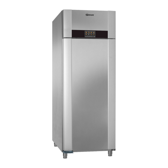
Page 10: General Description
General description Vapor system Compressor Front panel Condenser with air filter Display Gasket Air inlet Air distribution plate Door Supports Wall rail Foot pedal opener 765041938 Rev. 002... -
Page 11: Electrical Connection
If it is a product connected to an external compressor unit, it must be examined by the company who has connected the product to the unit. Outside the guarantee period, it is advisable to use the service advised by Gram Commercial, if possible. If this is not the case, assistance is required from a refrigeration company with knowledge of Gram’s products. -
Page 12: Humidifier
Repairing of electrical/technical parts may only be performed by a service electrician from Gram Commercial or an authorised refrigeration company with knowledge of Gram’s products. Do not use the product before all coverings are installed, so that live or rotating machine parts can not be touched. -
Page 13: Water Connection
Water connection To provide proper steam production, the humidifier must be connected to a water supply. To assure ideal steam production, it is important that the electrical conductivity of the inlet water is measured by the installer, to assure it is within standard range. See Below Box! Please note the following: The electrical conductivity of the water must be in the range: 200-800 µS/cm.* The temperature of the inlet water must not exceed 40°C. -
Page 14: General Use
General use Do not block vent holes in the front panel. Do not damage the refrigeration system parts. During normal operation, some parts of the refrigeration system in the compressor compartment might reach high temperatures, and could therefore cause burns if touching these components. Do not use electrical devices inside the product. -
Page 15: Commissioning, Functional Description
Commissioning, functional description In order to ensure reliable processes for Freezing, Storage, Thawing, Proving and Holding the cabinet must be furnished with controls to regulate the air temperature, ventilation and relative humidity. The operating modes of Storage, Thawing, Proving and Holding can be connected up manually. -
Page 16: Connection And Disconnection Of The Main Circuit Breaker
Connection and disconnection of the main circuit breaker The unit is furnished with a two-pole main breaker, which is located behind the tiltable control panel. When it has been disconnected, the controls and all components that are accessible without opening the control panel are disconnected from the power supply. If the main breaker is connected, then the controls and the other components are connected to the power supply. -
Page 17: User Interface To The Unit (Touchscreen)
When the unit is connected with the lighting mains, and the main breaker switched on, then the standby display is shown on the screen: (fig. 1). The Gram logo and the unit type "GA 950" as well as the date and time are shown on a field with a blue background. Please check that the correct date and time are displayed. -
Page 18: Selection Of Language
In order to change the settings for the date, time, formats, units or menu language, you need to press the button on the keyboard (machine symbol) in the lower right corner of the screen (fig. 3). The factory setting for the language is English. When you press the button , the menu for settings for the unit opens (fig. -
Page 19: Setting Of Clock (Time)
Setting of clock (time) The clock is set by touching the field with the time under the text "Time" (fig. 7): Fig. 7 Fig. 8 Enter the desired time directly using the numerical keypad and confirm with the "OK" button (fig. -
Page 20: Setting Of Date Format
Setting of date format Set the date format by pressing the "DD/MM/YYYY" field (fig. 11). Fig. 11 Fig. 12 The choice between the sequence day/month/year and month/day/year is now shown (fig. 12): Select by pressing. Season: summer time/winter time Setting of the season, i.e. the setting of winter/summer time is done by pressing on the field under the text "Summer time"... -
Page 21: Setting Of Ending Times For Programs For Each Weekday
Fig. 15 Fig. 16 Here, you can choose to display temperatures in Celsius or Fahrenheit for all displays in the controls (fig. 16). When you have made all the changes to the settings, then return to the Settings menu (fig. 4) for the unit by pressing the "OK"... -
Page 22: Preconfigured Programs
Fig. 20 Fig. 20a Enter a time. In order to jump over a day, the symbol „---„ (fig. 20a) needs to be inserted on the desired day. With "OK", you save what you entered for this weekday, or you can return to the weekly overview (fig. -
Page 23: Selection Of Ending Time For The Program
Further touching of the Master symbol opens a window with an ending time for the program (ready at) on the following day. Selection of ending time for the program A menu is opened in which the ending time for the program is selected, and the default - setting of "Weekday"... -
Page 24: Changing Of Established Date And Ending Time For The Program
Changing of established date and ending time for the program To do this, press on the "Calendar" field (fig. 26) Fig. 26 Fig. 27 The calendar menu (fig. 27) will be displayed. Here, the date can be changed by touching the date fields. Selections for changing the time can be opened by touching the time window. -
Page 25: Changing Of Further Settings Before Program Start
Changing of further settings before program start In order to adjust a preconfigured program, touch the button on the keyboard with the Master symbol. The selected symbol is displayed with a blue edge, and the "Settings" button (symbol with sliding button) is shown in blue, which means that it has been activated (fig. - Page 26 you must choose selection, see the first section. For example, to disconnect holding you must make the same selection under With "OK" the values are accepted and the menu closed. The selection menu "Save recipe ?" is then shown (fig. 31) Saves the entered values temporarily and accordingly runs the execution of the program activated below only once.
-
Page 27: Display During Program Execution (Fig. 32)
Display during program execution (fig. 32) The top line shows the phase of the program execution currently running depending upon the program selected: Freezing, Storage, Thawing, Proving, Holding The field in the upper right rectangle shows the currently running program phase and the associated remaining (residual) time. A red triangle is shown as an alarm symbol in the event of an alarm. In the window in the middle, the The green bar at the symbol for the currently bottom of the display The current value for the shows the total program temperature or the relative running program is shown at the execution in proportion humidity is shown in the left, in the centre the ending time to the duration. lower right corner for the program and at the right a depending upon the button to interrupt the program. program phase. 765041938 Rev. 002... -
Page 28: Changing A Running Program
Changing a running program Fig. 33 Fig. 34 Touching the program symbol (fig. 33) opens the settings menu (fig. 34), where you can change the specifications for program phases that have not been run yet. Touching the field with the ending time for the program (fig. 35) opens the settings menus for date and time (fig. -
Page 29: Interruption Of The Currently Running Program
Interruption of the currently running program Touching the button causes the currently running program to be interrupted (fig. 36). Fig. 36 Fig. 37 A window opens where for verification purposes you are asked whether the program should really be halted (fig. 37). If ("YES") is selected, the program is stopped. - Page 30 Freezing Storage Thawing Proving Holding Fig. 39 Under these, there are fields containing the values for duration, temperature and relative humidity for the respective program phase. By touching the field for the respective program phase, for example, it is selected for the setting of its values. Then the fields, for example , are opened when touched.
- Page 31 With "OK" the values are accepted and the menu closed. The selection menu "Save recipe ?" is then shown (fig. 41) Saves the entered values temporarily and runs in a corresponding manner the commenced program sequence 1 x. Means that the menu is exited without changes.
- Page 32 Touching the program symbol (fig. 43) shows a selection of symbols for your own programs (fig. 44). Choose a symbol by touching it, and navigate back and forth between further symbols with "<" or ">". Change for example the picture from or exit the menu without changes with "<".
-
Page 33: Manual Programs
Manual programs The display start page (fig. 48) will save up to four different symbols. You can activate each one of these program phases separately to for example use the unit as a storage freezer or solely as a proving machine. Fig. -
Page 34: Alarms/Error Messages
Alarms/error messages If an error arises, an error message window is displayed on the screen, for example a room sensor error, and an acoustic alarm is issued. In order to acknowledge this alarm, you must touch the alarm window (the area with the black background). -
Page 35: Sensor Alarms
Sensor alarms Error message Description System reaction Sensor defective, not connected or short- Compressor runs for 5 min. ON and Room sensor error circuited. 5 min. OFF. Defrosting will be 45 min., and the Sensor defective, not connected or short- Evaporator sensor error evaporator fan will start 10 min. -
Page 36: Door Closing Mechanism
Door closing mechanism The door is equipped with a self-closing system. If the door is opened less than 90, it will close by itself. If the door is opened more than 90, it will stay open. The door can be opened by using the foot pedal. This leaves both hands free when placing foodstuffs the cabinet. -
Page 37: Door Gaskets
Door gaskets This chapter deals with the importance of a well-functioning door gasket. Gaskets are an important part of a refrigerator/freezer. Gaskets with reduced functionality, reduces the tightness of the cabinet. Reduced tightness might cause increased humidity, internal icing, an iced up evaporator (leading to reduced refrigeration capacity), and in worst case reduced lifecycle of the cabinet. -
Page 38: Service
If refrigeration fails, first investigate whether the unit has been unintentionally disconnected or switched off at the socket, or whether a fuse has blown. If it is not possible to find the cause of the refrigeration failure, please contact Gram service department. -
Page 39: Disposal
Disposal of an old cabinet is only available when we are delivering a new one at the same time. Cabinets must be fully defrosted and emptied prior to collection. Gram recognises that our products for the catering market are considered as WEEE when they become obsolete. To ensure that Gram’s responsibilities are handled correctly and environmentally friendly, we are signed up the largest Business to Business compliance scheme in the UK –... -
Page 40: Ec-Declaration Of Conformity
Aage Grams Vej 1, 6500 Vojens Tel.: 73 20 12 00 Product Model: Baker GA 950, Baker GA 550 Refrigerant: R134a, R404A, R290 Year: 2016 Directives The product is in compliance with all the essential health- and safety requirements... -
Page 41: Wiring Diagram
Wiring diagram 765041938 Rev. 002... -
Page 42: Piping Diagram
Piping diagram 765041938 Rev. 002... - Page 43 765041938 Rev. 002...
Need help?
Do you have a question about the BAKER GA 950 and is the answer not in the manual?
Questions and answers