Advertisement
READ AND SAVE THESE INSTRUCTIONS
®
Upon receiving unit, check for any damage
and report it immediately to the shipper. Also
check to see that all accessory items are
accounted for.
Move fan to desired location and fasten
securely through mounting holes in base.
Shims may be necessary depending upon
roofing material thickness. The diagram
below shows dimensions for Model CUBE.
Access to the motor compartment is
accomplished by removing the screws
designated "R" in Fig. 1. The cover can then
be removed and placed on a flat surface in
an area protected from strong winds.
The motor's amperage and voltage rating
must be checked for compatibility to the
supply voltage prior to final electrical
connection. For NFPA - restaurant CUBE
applications, the electrical supply must enter
the motor compartment through the breather
tube. For other non-flammable applications
the electrical supply can be routed through
the conduit chase between the curb cap and
the bottom of the motor compartment.
Consult local code authorities for your
specific requirements.
A drain trough is provided on all CUBE fans
for single-point drainage of water and
residue. Some means for collection of this
residue must be provided, either a container
directly under the trough or use of an
adapter and pipe to carry the residue to a
remote collection point. An optional grease
trap with water separator baffles is available
from your Greenheck representative.
Dimensional Data
B
R
A
Fig. 1
Installation, Operating and Maintenance Manual
CUBE-098, 101, 101HP, 121, 131 19
CUBE-141, 141HP
CUBE-161, 161HP, 161XP
CUBE-180
CUBE-180HP
CUBE-200
*C
CUBE-200HP
D
CUBE-220, 220HP
CUBE-240, 240HP, 240XP
CUBE-300, 300HP, 300XP
CUBE-360, 360HP, 360XP
1
3
/
4 in.
CUBE-420
CUBE-480
Dimension "A" is the inside dimension of the curb cap. The roof curb should be 1
the curb cap to allow for roofing and flashing.
All dimensions are in inches. *May vary depending on motor size.
Installations
Recommended
General
Ventilation
Installation
3
/
4 in.
8 in. or 12 in. min.
Roof Deck
1
1
/
4 in.
Recommended
Commerical
Kitchen
Installation
Minimum 40 in.
Discharge
Height
(per NFPA)
Grease
Trap
8 in. min.
Roof Deck
MODEL
A
B
7
24
/
28
8
22
28
7
/
29
8
30
35
3
/
28
8
34
42
3
/
33
4
40
50
5
46
58
/
39
8
3
52
65
/
44
16
3
58
74
/
48
16
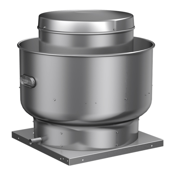
Model CUBE Belt Drive
Upblast Centrifugal
Roof Exhaust Fan
Wiring by
Others
Damper
Recommended
Duct and
Damper Size
Recommended
Roof Opening
Welded Duct
by others
min. of 18 in.
above roof
deck (per
NFPA)
Recommended
Roof Opening
Shaft
Damper
*C
D
Bearings
Size
1
3
3
/
17
/
/
12x12
14
4
8
4
3
/
19
3
/
3
/
16x16
18
4
8
4
3
/
4
1
5
/
21
18x18
20
8
3
/
4
1
7
/
25
1
/
1
24x24
26
8
2
36
29
1
30x30
32
1
3
/
29
/
36x36
38
8
8
1
1
/
4
3
1
/
35
/
42x42
44
4
4
1
1
/
36
1
/
48x48
50
8
2
PN 457693
Factory Wired
Motor to
Disconnect
1
1
/
4 in.
Optional
NEMA 3R
Disconnect
factory wired
from motor to
disconnect
through the
breather tube
Vented Curb
Extension
Liquid Tight
Flexible Conduit
by Others
Approx.
Roof
Unit
Opening
Weight
1
1
/
x 14
/
66
2
2
1
/
x 18
1
/
87
2
2
126
1
/
x 20
1
/
2
2
142
1
/
x 26
1
/
175
2
2
1
1
/
x 32
/
313
2
2
1
1
/
x 38
/
440
2
2
1
1
/
x 44
/
578
2
2
1
1
/
x 50
/
675
2
2
1
/
in. less than
2
Advertisement
Table of Contents

Related Manuals for Greenheck CUBE-098


Summary of Contents for Greenheck CUBE-098
- Page 1 Recommended Roof Opening Dimensional Data Approx. Shaft Damper Roof MODEL Unit Bearings Size Opening Weight CUBE-098, 101, 101HP, 121, 131 19 12x12 x 14 CUBE-141, 141HP 16x16 x 18 CUBE-161, 161HP, 161XP CUBE-180 CUBE-180HP 18x18 x 20 CUBE-200 CUBE-200HP CUBE-220, 220HP...
- Page 2 Pre-Starting Checks Check all fasteners for tightness. The wheel should rotate freely and be aligned as shown in Fig. 2. Wheel position is preset and the unit is test run at the factory. Movement may occur during shipment, and realignment may be necessary. Centering can be accomplished by loosening the bolts holding the drive frame to the shock mounts and repositioning the drive frame.
- Page 3 MAINTENANCE Belts tend to stretch after a period of time. They should be checked periodically for wear and tightness. When replacing belts, use the same type as supplied with the unit. Matched belts should always be used on units with multigroove pulleys. For belt replacement, loosen the tensioning device far enough to allow removal of the belt by hand.
- Page 4 WARRANTY Greenheck warrants this equipment to be free from defects in material and workmanship for a period of one year from the date of purchase. Any units or parts which prove to be defective during the warranty period will be replaced at our option when returned to our factory, transportation prepaid.
Need help?
Do you have a question about the CUBE-098 and is the answer not in the manual?
Questions and answers