
Related Manuals for Terex TA300


Summary of Contents for Terex TA300
- Page 1 TEREX Equipment Limited Operations Manual 15504764 OHE11001 Original Operating Instructions...
- Page 2 This page is intentionally left blank...
- Page 3 TEREX Equipment Limited Operations Manual Re-order Issued by; Customer Support Department Terex Equipment Limited Newhouse Industrial Estate Motherwell, ML1 5RY Scotland Tel; +44 (0) 1698 732121 Fax; +44 (0) 1698 503210 http//:constructionsupport.terex.com www.terex.com OHE11001 Re-order Part Number 15504764 This controlled document is the original instruction and should remain with the vehicle at all times.
- Page 4 This page is intentionally left blank...
- Page 5 The right to change specifications, equipment and maintenance instruc- tions at any time without notice, is reserved as part of the Terex Equip- ment Limited policy of continuous development and improvement of the product.
- Page 6 This page is intentionally left blank...
- Page 7 ONLY TRAINED COMPETENT PERSONNEL SHOULD BE ALLOWED TO OPERATE THIS VEHICLE The operator is responsible and must be familiar with the contents of the Operations Manual and any Local / National regulations prior to operating this vehicle.
- Page 8 This page is intentionally left blank...
- Page 9 CALIFORNIA Proposition 65 Warnings WARNING: Diesel engine exhaust and some of its constituents are known to the State of California to cause cancer, birth defects, and other reproductive harm. WARNING: Battery posts, terminals and related accessories contain lead and lead compounds, chemicals known to the State of California to cause cancer and reproductive harm.
- Page 10 This page is intentionally left blank...
- Page 11 EC DECLARATION OF CONFORMITY MANUFACTURER'S NAME AND FULL ADDRESS: PERSON AUTHORISED TO COMPILE TECHNICAL FILE DIRECTIVES COMPLIED WITH: DESCRIPTION OF MACHINERY: TEREX MAKE: MODEL/DESIGNATION: INSPECTOR: UNIT SERIAL NUMBER: CERTIFICATE NUMBER: FULL QUALITY ASSURANCE (Annex VIII): DATE OF MANUFACTURE: FOR AND ON BEHALF OF THE MANUFACTURER:...
- Page 12 SPARE PARTS STATEMENT When carrying out repairs, alterations or fitting attachments, it is important that only genuine spare parts are used to ensure the operating safety of the machine is not impaired. It is only by using genuine parts that the technical requirements stipulated by the manufacturer can be maintained.
- Page 13 EC DECLARATION OF CONFORMITY MANUFACTURER'S NAME AND FULL ADDRESS: PERSON AUTHORISED TO COMPILE TECHNICAL FILE DIRECTIVES COMPLIED WITH: DESCRIPTION OF MACHINERY: TEREX MAKE: MODEL/DESIGNATION: INSPECTOR: UNIT SERIAL NUMBER: CERTIFICATE NUMBER: FULL QUALITY ASSURANCE (Annex VIII): DATE OF MANUFACTURE: FOR AND ON BEHALF OF THE MANUFACTURER:...
- Page 14 SPARE PARTS STATEMENT When carrying out repairs, alterations or fitting attachments, it is important that only genuine spare parts are used to ensure the operating safety of the machine is not impaired. It is only by using genuine parts that the technical requirements stipulated by the manufacturer can be maintained.
- Page 15 EC DECLARATION OF CONFORMITY MANUFACTURER'S NAME AND FULL ADDRESS: PERSON AUTHORISED TO COMPILE TECHNICAL FILE DIRECTIVES COMPLIED WITH: DESCRIPTION OF MACHINERY: TEREX MAKE: MODEL/DESIGNATION: INSPECTOR: UNIT SERIAL NUMBER: CERTIFICATE NUMBER: FULL QUALITY ASSURANCE (Annex VIII): DATE OF MANUFACTURE: FOR AND ON BEHALF OF THE MANUFACTURER:...
- Page 16 SPARE PARTS STATEMENT When carrying out repairs, alterations or fitting attachments, it is important that only genuine spare parts are used to ensure the operating safety of the machine is not impaired. It is only by using genuine parts that the technical requirements stipulated by the manufacturer can be maintained.
-
Page 17: Table Of Contents
CONTENTS 1 INTRODUCTION Introduction....... 1-1 Safety Alert Symbol ......1-1 Hazard Classification . - Page 18 Intentionally Left Blank...
- Page 19 9 TECHNICAL DATA TA300 ........9-3...
- Page 20 Intentionally Left Blank...
-
Page 21: Introduction
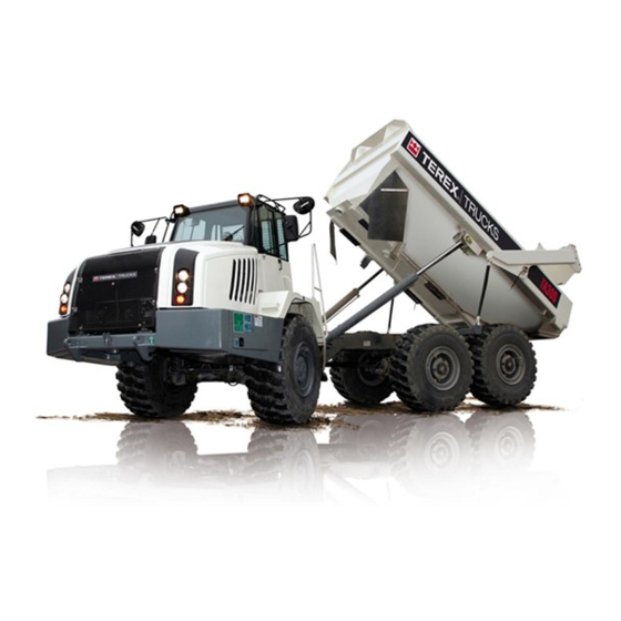
The Terex articulated haulers are 3 axle types with an oscillation and articulation pivot joint between the tractor and trailer units. Articulation is achieved by frame steering. The machine has part time or full time 6 wheel drive controlled by the operator. - Page 22 Introduction DANGER indicates an imminently hazardous situation which, if not avoided, will result in death or serious injury. DANGER WARNING indicates a potentially hazardous situation which, if not avoided, could result in death or serious injury. WARNING CAUTION indicates a potentially hazardous situation which, if not avoided, CAUTION may result in minor or moderate injury.
- Page 23 Introduction PRODUCT IDENTIFICATION NUMBER - PLATE LOCATION Information regarding the machine model, code and chassis serial number is found on the unit serial number plate on the rear right of the front frame. The machine model and serial number should always be referenced in any correspondence with your dealer or factory.
-
Page 24: Theft Deterrent Practices
Introduction THEFT DETERRENT PRACTICES General The owner/operator should take the following precautions to discourage theft, to aid in the recovery in the event that the machine is stolen, or to reduce vandalism. Actions to Discourage Theft and Vandalism Remove all keys any time the machine is left unattended. At night lock all doors and attach, secure or lock all anti-vandalism and anti-theft devices on the machine. - Page 25 Safety 2 - Safety...
- Page 26 Safety Intentionally Left Blank...
- Page 27 Safety SAFETY The machine should be properly operated and maintained to keep it in a safe, efficient operating condition. Be sure that all controls are free of mud, grease, or other matter that might cause slips hazardous to the operator, serviceman, or other personnel or equipment. Report all malfunctions to those responsible for maintenance, and, do not operate the equipment until corrected.
-
Page 28: General
Safety SAFETY General • Read this operations manual and learn the operating characteris- tics and limitations of the machine. Know what operating clear- ances the machine requires. • Read and understand all the safety signs prior to operation. • If the safety signs are obstructed by dirt or debris, clean them using mild soap and water prior to operation. -
Page 29: Articulation And Oscillation Locks
Safety CAUTION The protection offered by the roll over and falling object pro- tective structure may be impaired if it has been subjected to any modification or damage. Unauthorized modification will Articulation and Oscillation void certification. Lock - ‘Locked Position’ Articulation and Oscillation Lock •... -
Page 30: Preventing Fire Hazards
Safety Preventing Fire Hazards General Fire Precautions • Make sure the machine has a fire extinguisher and that it is accessible and fully charged. (Not furnished with the machine). • Never use an open flame as a light anywhere on, or around, the machine. -
Page 31: Mounting And Dismounting
Safety • Follow manufacturer’s recommendations when handling and using engine-starting fluids and disposing of spent containers. Do not puncture or burn empty containers. These fluids are explosive and highly flammable. Electrical Hazard Precautions • Never smoke or allow open flames or sparks near batteries. •... -
Page 32: Pre-Starting
Safety Pre-Starting • If the engine is to be started and run indoors, ensure proper ven- tilation to remove deadly exhaust gases. • Always perform 'Pre-Starting Inspection' instructions described in section 4 to ensure the machine is ready for operation. •... - Page 33 Safety • Sound the horn before starting the engine or beginning to move the machine; two blasts for forward and three blasts for reverse. • Watch for ground crew and other personnel on foot. Sound the horn as a warning before setting the machine in motion and when approaching ground crew.
-
Page 34: Roading
Safety • Always watch for holes, soft edges or other hazards when back- ing to dump over a spoil bank. • Always apply the brakes with the Parking-Emergency brake con- trol when the machine is being loaded or when dumping a load. •... -
Page 35: Lubrication And Servicing
Safety Lubrication and Servicing • Do not allow unauthorized personnel to service or maintain this machine. Study this operations manual and the maintenance manual before starting, operating or servicing this machine. Always follow procedures and safety precautions detailed throughout the maintenance manual. •... -
Page 36: Scrapping The Machine
Safety • Always use a self-attaching chuck with a long airline, and, stand to one side while the tyre is inflating. Refer to Section 160-0050, WHEEL RIM AND TYRE in the maintenance manual. • Do not work under or near an unblocked or unsupported raised operator’s cab. -
Page 37: Mirror And Cctv
Safety Mirrors and CCTV CAUTION The operator must survey their surroundings before entering the machine, and check their field of vision prior to and dur- ing operation of the machine. All mirrors must be adjusted when installed, and prior to operating the machine, to achieve optimum visibility and thus minimize the risk of injury to themselves and others. - Page 38 Safety When all the mirrors have been fitted, the machine has a total of four mir- rors, designated A to D respectively, and positioned generally as illus- trated. The area surrounding the machine is to be considered as two distinct fields of view, illustrated below as areas 1 to 9 in the immediate vicinity, and areas 10 to 15 at a radius of 12 m from the operator when seated.
-
Page 39: Wheels And Tyres
Safety Wheels and Tyres If tyres on the machine were inflated at the factory with dry nitrogen gas, the tyre walls will be marked 'N' and the following factory installed decal will be found mounted on the fenders. NOTICE: Tyres on this machine are factory inflated with dry nitrogen. It is recommended that dry nitrogen be used exclusivel y for all tyre pres- sure adjustments as well as inflation of replacement tyres. -
Page 40: Avoid Tyre Explosion Hazard
Safety Avoid Tyre Explosion Hazard CAUTION AT LEAST AT LEAST 15m (50ft) 460m (1 500ft) Whenever a machine’s tyre(s) is (are) exposed to excessive heat such as a machine fire or extremely hot brakes, the hazard of a subsequent violent tyre explosion must be recognized. All nearby persons must avoid approaching the machine so as not to be physically endangered in the event of an explosion of the tyre and rim parts. -
Page 41: Emergency Exit From Cab
Safety Emergency Exit from Cab Normal access to, and egress from, the cab is facilitated via the door on the left-hand side . However, in an emergency, an alternative exit can be gained via the side windows. A hammer is provided to break the left-hand or right-hand side window glass to facilitate safe egress. -
Page 42: Decals And Instruction Plates
MOT00653 16 . Decal - Hydraulic Control 17 . Decal - Nitrogen Filled Tyres WINDOW STOP 18 . Decal - Warning Crush Hazard GIGA V01.04.01 TA300-A11 MCU HV008 SV08.08.08 km/h 88.88.2011 88.88.88 000000 19 . Decal - Diagnostic Points 20 . Decal - Notice Cab Jack 21 . - Page 43 Safety Decals and Instruction Plates Pictorial Decal Set 9361787 9271069 Battery Earth (1798) CE Marking (1799) Hook Point (1797) 15331997 Sound Power (1976) 15314811 Body Control (1800) 15318464 Steering Column Adjustment (1801) 15331998 Sound Power (1977) 15321641 Park Brake (1805) Emergency Exit (1804) MOT00177 15332624...
-
Page 44: Product Identification No
Safety Pictorial Decal Set Serial Plate TEREX EQUIPMENT LIMITED NEWHOUSE INDUSTRIAL ESTATE MOTHERWELL, SCOTLAND. ML1 5RY. MODEL NO. PRODUCT IDENTIFICATION NO. MAX. RATED PAYLOAD lb /kg MASS UNLADEN lb /kg STRUCK CAPACITY yd³ /m³ ENGINE POWER hp /kW YEAR OF MANUFACTURE... - Page 45 Safety Safety Decals Set ISO Standard KPH MPH % KPH MPH 15334645 TA250/300 Gradeability Chart (1867) 15334761 Crush Hazard Warning. Apply Park Brake, Shift to neutral (1876) 15334762 Skin Injection Warning. Relieve pressure before 15334754 service. Use card to search for leaks (1877) Crush From Articulation Warning.
- Page 46 Safety Safety Decals Set ISO Standard 15334767 15334774 Burn Hazard, allow to cool before Welding Notice. See handbook for opening (1881) welding procedures (1888) 15334768 Anti-freeze Notice. See handbook 15334777 Cab Jack Notice (1889) for correct concentration (1882) 15334772 Nitrogen Filled Tyres. Use 15334780 Reverse Warning.
- Page 47 Safety Safety Decals Set ISO Standard PSI / BAR 15335077 Batteries Warning. Explosive, keep 15335079 all flames and sparks away (1891) Pressurised Accumulator Warning. Do not weld, keep away from flames. Relieve all pressure before servicing (1893) 15334773 Power Down Notice. Power down truck when not in use (1887) 0 - 50 kV 10 ft (3m)
- Page 48 Safety Safety Decals Set ISO Standard MOT00180 250h 500h 1000h - 4000h 15362924 TA250/300 Service Lubrication Chart. See Operator Handbook section 8 for details MOT00170 TA250/300 Diagnostic Point 2-24...
- Page 49 Do not repair. TA30 Unauthorised modification TA35/40 will void certification. TA350/400 Tighten fastners MANUFACTURED FOR/BY TEREX EQUIPMENT LTD. - SCOTLAND TA250/300 periodically. 15332782 ROPS and FOPS Certification (1812) MOT00179 WARNING TA250/300 Gradeability Chart Crush Hazard Install support Death or serious before servicing.
- Page 50 Safety Safety Decals Set ANSI Standard WARNING WARNING WARNING Improper operation or Read and understand maintenance can result operator's manual and all in serious injury or safety signs before using death. or maintaining machine. If you do not understand the information in the manuals, consult your supervisor, the owner or Entanglement Hazard.
- Page 51 Safety Safety Decals Set ANSI Standard NOTICE NOTICE NOTICE Use nitrogen only Jump starting with Jump start using to inflate tyres. welding equipment will identical battery Power down truck result in damage to the pack. 15333283 electrial system. when not in use Nitrogen Filled Tyres Notice or damage may 15333282...
- Page 52 - HYDRUALIC OIL. REFER TO "RECOMMENDED LURICANTS". - EXTREME PRESSURE GEAR LUBRICANT. REFER TO "RECOMENDED LUBRICANTS". EP,NLGI - EXTREME PRESSURE LITHIUM No. 2 GREASE (WITHOUT "MOLY"). PAG OIL - POLYALKLENE GLYCOL (PAG) COMPRESSOR LUBRICATING OIL - LOW VISCOSITY (ISO46) 15362898 TA300 Service Lubrication Chart 2-28...
- Page 53 Controls and Operating 3 - Controls and Operating...
- Page 54 Controls and Operating Intentionally Left Blank...
-
Page 55: Controls And Instruments
Controls and Operating CONTROLS AND INSTRUMENTS MOT00064 5 6 7 8 10 11 12 13 14 15 STOP GIGA V01.04.01 TA300-A11 MCU HV008 SV08.08.08 km/h 88.88.2011 88.88.88 000000 MENU SELECT 1 - Side Window Demister 22 - Transmission Gear Shift Control... -
Page 56: Fuse / Relay Box
Controls and Operating FUSE / RELAY BOX... - Page 57 Controls and Operating Fuse Name Size Function Master Fuse Terminal 30 Master Fuse Terminal 30 Master Fuse Terminal 15 Master Fuse Terminal 15 Not Connected 7.5A Transmission Controller Emergency Operation Spare Interior Light 7.5A Hazard Warning DC-DC Convertor 7.5A Telematics Interface Work Socket 24V Air Seat Compressor Hydraulic Oil Sensors...
- Page 58 Controls and Operating Fuse Name Size Function Not Connected Difflock Spare Spare Camera System Body Position Proximity Spare Main Controller Start / Stop Button Not Connected Front Work Light Rear Work Light Spare Not Connected Spare TCU Diagnostic Interface Steering Column Switch 7.5A Dashboard Transmission Temperature Sensor...
- Page 59 Controls and Operating Fuse Name Size Function Main Controller Hydraulic Block Not Connected Heated Mirror Not Connected Not Connected Spare Not Connected Air Conditioning Spare Engine Management System Ignition / Telematics Engine Management System Main Controller Not Connected Not Connected Not Connected Not Connected Not Connected...
- Page 60 Controls and Operating Relay Name Type Function Micro Relay 12V Terminal 15 Micro Relay Differential Lock Power relay Front Work Lights Power relay Rear Work Lights Micro Relay Horns Power relay Mini Relay Power relay Emergency Operation Power relay Power relay Micro Relay Micro Relay Wiper Motors...
-
Page 61: Basic Data
Controls and Operating BASIC DATA MOT00233 STOP AUTO ERROR CONVERT OMNIA km/h 999.9 100% 99.9 ERROR CODE 88 : 88 : 88 000000 Dashboard Display Operating the machine is supported by a combined dashboard display. The dashboard display provides machine information to the operator through various gauges and indica- tors. -
Page 62: Warning Lights And Symbols
Controls and Operating Warning Lights and Symbols - Left of Dashboard Display MOT00065 1. Engine Coolant Level Low - Illuminates when the coolant level drops STOP below the safe operating level. 2. Engine Oil Pressure Low - Illuminates when the engine oil pressure drops below the safe operating pressure. - Page 63 Controls and Operating Warning Lights and Symbols - Right of Dashboard Display 1. Transmission Retarder Active - Illuminates when the transmission retarder is active. 2. Engine Over Speed - Illuminates when the engine speed rises above the safe operating speed (Engine Speed > 2300 Rpm). The operator should take action to slow the vehicle.
- Page 64 Controls and Operating Warning Lights and Symbols - Below Dashboard Display MOT00085 1. High Beam - Illuminates when high beam is switched on. 2. Direction Indicators - Flashes when the indicator lights (left or right) are operating. NOTICE: The indicator flash is accompanied with buzzing signal. Warning lights and symbols -Below 3.
-
Page 65: Instruments
Controls and Operating Instruments MOT00155 STOP MOT00234 STOP EMERGENCY AUTO MODE CONVERT AUTO ERROR LOCKUP OMNIA km/h 999.9 100% 99.9 ERROR CODE 88 : 88 : 88 000000 MOT00096 km/h 000000 Dashboard Display 1. Tachometer - Driven from the engine ECU, the tachometer indicates the number of engine crankshaft revolutions per minute. -
Page 66: Menu Screen And Buttons
Controls and Operating Menu Screen and Buttons MOT00235 STOP AUTO ERROR LOCKUP OMNIA km/h 999.9 100% 99.9 ERROR CODE 88 : 88 : 88 000000 Dashboard Display 1. Menu Screen - The following illustrations show the sequential display in its five possible screens. On initial starting of the vehicle, the display shows the Power Up Screen (1) and then automatically scrolls to the Main Screen. - Page 67 Controls and Operating Screen - 1: MOT00120 PowerUp Screen - Displays the Terex logo(1). GIGA V01.04.01 TA300 The Date (2) and Time (3) are displayed at the bottom of the screen. MCU HV008 SV08.08.08 Dashboard display software version (4) and MCU software version (5) are displayed at the top of the screen.
- Page 68 Controls and Operating wiper intermediate Status Bar is shown just as the control stock MOT00237 wiper switch is set to “Intermediate” position.The intermediate sta- tus can be set from step 1 (slow - 15 sec pause time) to step 6 AUTO ERROR (fast –...
- Page 69 Controls and Operating Screen - 4: MOT00161 Brightness and RTC Setup Screen DISPLAY BACKLIGHT 1024 This screen allows separate setting of the dashboard display’s LCD and LCD BACKLIGHT 1024 INSTRUMENTS BACKLIGHT 1024 instruments backlight values. There are two different value settings, 2011 DATE adjustable for day (Control Stock Lights Switch OFF) and night (Control...
- Page 70 Controls and Operating TRANSMISSION DIAGNOSTICS is based on the ZF TCU_1 CAN Mes- sage. In the ‘ERROR CODE’ the ZF TCU ERROR CODE is displayed cyclically in 1 second intervals. The display indicates gear selected and driving direction as follows: Manual Mode - When driving with the shift selector in manual range, the bars only are shown in position 1, and, driving direction and gear selected 1 - Bars show gear ranges and full display...
-
Page 71: Switches
Controls and Operating Switches MOT00122 1. Hazard Warning Lights - Press the bottom of the switch to make the indicators flash simultaneously as hazard warning lights. The direction indicator warning lamp on the instrument panel will flash (ensure that the ignition / power is ON). To switch the hazard lights off; press the top of the switch. - Page 72 Controls and Operating 11.N/A 12.N/A. 13.Heated Mirrors - Press the bottom of the switch to activate the heated mirrors. To switch off, press the top of the switch. MOT00127 14.Rear Working Lights - Press the bottom of the switch to operate the rear working lights.
- Page 73 Controls and Operating '0' - Power switched off. All electrical systems are inoperative. NOTICE: Hazard warning light illumination is possible when the switch is in 0. '1' - Power switched on, instruments, gauges and warning lights register as appropriate. All electrical systems are operative. The key must remain in this position whilst operating the machine.
-
Page 74: Controls
Controls and Operating Controls MOT00079 High Beam Dipper, Direction Indicator, Windscreen Wiper/Washer Head- light / Parking / Front Working Light and Horn 1. High Beam Dipper and Flasher: Neutral Position = Dipped Beam Control Upwards = High Beam Flash Control Downward with Lights On = High Beam Continuous High Beam continuous is possible only if the steering lever switch is set to MOT00080 position 1, 2 or 3 (Lights ON). -
Page 75: Heater
Controls and Operating Heater The blower control (3) is rotated to select one of three blower speeds. Air direction can be adjusted by turning the direction controls (4 and 5). The temperature control (1) is rotated to vary the heater output tempera- ture. -
Page 76: Operator's Seat Air Suspension
Controls and Operating Operator's Seat - Air Suspension The air seat only reacts when the driver sits on the seat. When unoccu- pied, the seat sinks to the lowest position to allow easier access. The following is the list of controls to adjust the seat: 1. -
Page 77: Operator's Seat Operation
Controls and Operating Operator's Seat - Operation To achieve the most comfortable driving position, adjust the seat as fol- lows: 1. Sit in the seat. 2. Pull up and immediately release the height and weight adjustment (1) handle - this will set the seat to cater for the operator’s weight. Sit com- pletely still while carrying out the adjustment . - Page 78 Controls and Operating 7. The height and curvature of the backrest cushion can be adjusted by rotation of the lumber support (9) at the rear of the cushion. 8. Pull up the handle (5) and adjust the backrest to the required angle, release the handle when the required position is achieved.
-
Page 79: Seat Belt
Controls and Operating Seat Belt Retractable seat belts (1) are installed on both the operator’s seat and the jump seat. The seat belts require no external adjustment and allow free- dom of movement for proper manipulation of all controls. NOTICE: To extract the jump seat belt, the button on the housing must be pressed. -
Page 80: Machine Controls
Controls and Operating MACHINE CONTROLS Braking The dual circuit brake system is applied during normal operation by using the service brake pedal or, in an emergency, by using the park emergency brake control. The 'Front Brake System' warning light and the 'Rear Brake System' warning light are located on the instrument panel. -
Page 81: Transmission Retarder
Controls and Operating Transmission Retarder MOT00073 This switch is used to request the transmission retarder. The retarder will engage when the switch is pressed (refer to Section 3) and provided that the transmission 'Stop' warning light is 'OUT', the transmission is in 'lockup', accelerator pedal is released (off gas) and the transmission oil temperature is within operating range. -
Page 82: Engine Brake
Controls and Operating Engine Exhaust Brake MOT00126 There are 2 positions for the switch. Press the top of the switch to request the engine exhaust brake. This position applies the engine exhaust brake when service brake is applied. Press the bottom of the switch. This posi- tion applies the engine exhaust brake when throttle pedal is not active.The engine exhaust brake symbol illuminates on the display screen when the engine exhaust brake is engaged. -
Page 83: Engine
Controls and Operating Engine Electronic Foot Pedal The electronic foot pedal provides an electrical signal to the engine's fuel control system in proportion to the degree of pedal actuation. NOTICE: The engine MUST be started with the foot 'OFF' the electronic foot pedal. -
Page 84: Xpi Fuel Injection System
Controls and Operating MOT00103 STOP 1. Engine Management System 5. Engine Check Light 6. Diagnostic Switches 2. XPI Fuel Injectors 3. Electronic Foot Pedal 7. Diagnostic Test Point 4. Engine Stop Light XPI Fuel Injection System - Description 1. Engine Management System (EMS) - Receives electronic inputs from the driver as well as from sensors that provide information elec- WARNING tronically, such as speed, oil pressure and temperature, boost pressure... - Page 85 Controls and Operating WARNING Due to the high fuel pressure, leakage can cause jets of fuel that penetrates through the skin! Always consider the high pressure part of the system (accu- mulator and high pressure lines) as pressurized. The pres- sure could be as high as 3000 bar.
- Page 86 Controls and Operating MCU ERROR CODES Error Code Description of Error Check DASHBOARD DISPLAY- DASH NOT LIVE ECU NOT LIVE TCU NOT LIVE Control Stock- LEVER NOT LIVE --------------- --------------- --------------- --------------- --------------- --------------- MCU OUT_00 X1:18 SHORT K2_MainRelayTerminal15_ON MCU OUT_00 X1:18 BREAK K2_MainRelayTerminal15_ON MCU OUT_01 X1:17 SHORT E5_ParkingLights_ON...
- Page 87 Controls and Operating Error Code Description of Error Check MCU OUT_08 X1:2 SHORT E5_HighBeam_Left_ON MCU OUT_08 X1:2 BREAK E5_HighBeam_Left_ON MCU OUT_09 X1:3 SHORT P8_FlashingReverseLamp_ON MCU OUT_09 X1:3 BREAK P8_FlashingReverseLamp_ON MCU OUT_10 X1:4 SHORT E6_LowBeam_Right_ON MCU OUT_10 X1:4 BREAK E6_LowBeam_Right_ON MCU OUT_11 X1:5 SHORT E20_ReverseLamp_ON MCU OUT_11 X1:5 BREAK E20_ReverseLamp_ON...
- Page 88 Controls and Operating Whenever the 'Stop' or 'Check' light comes on, the EMS will determine MOT00075 where the problem is and will store this information in its memory. If the malfunction is intermittent, the lights will come on and go off as the computer senses the changing engine condition.
- Page 89 Controls and Operating ENGINE FAULT CODES Fault codes generated in the CAN network are sent via CAN message. This document describes how to interpret these fault codes. Abbreviations Abbreviation Explanation Suspect Parameter Number Failure Mode Identifiers Failure Mode Identifiers Explanation of FMI codes. Code Explanation Data valid but above normal operational range (that is, engine overheating)
- Page 90 Controls and Operating List of fault codes SPN Name SPN Description FMIa Engine Throttle Position The position of the valve used to regulate the 0,1,2,3,4,5 supply of a fluid, usually air or fuel/air mixture, to an engine. Engine Fuel Delivery Pressure Gauge pressure of fuel in the system as deliv- ered from the supply pump to the injection pump.
- Page 91 Controls and Operating SPN Name SPN Description 1761 Aftertreatment 1 SCR Cata- A special catalyst uses a chemical reagent to 0,1,3,6,8 lyst Tank Level reach legal requirement for NOX emissions. This parameter indicates the reagent level within that catalyst tank. 2797 Engine Injector Group 1 A first collection of fuel injector circuits that are...
- Page 92 Controls and Operating SPN Name SPN Description 4341 Aftertreatment 1 SCR Catalyst Used to identify the applicable J1939-73 FMI 2,3,5,6 Reagent Line Heater 1 Prelimi- detected in the SCR catalyst reagent line nary FMI heater 1, by the manufacturer’s control soft- ware in exhaust bank 1.
- Page 93 Controls and Operating Error Code Description of Error Check MCU OUT_06E X2:12 SHORT Q14_TransmissionFan_Speed_PWM MCU OUT_06E X2:12 BREAK Q14_TransmissionFan_Speed_PWM MCU OUT_07E X2:11 SHORT SystemHydraulic_unloader_valve MCU OUT_07E X2:11 BREAK SystemHydraulic_unloader_valve MCU OUT 08E X2:2 SHORT MCU OUT 08E X2:2 BREAK MCU OUT 09E X2:3 SHORT MCU OUT 09E X2:3 BREAK MCU OUT 10E X2:4 SHORT MCU OUT 10E X2:4 BREAK...
- Page 94 Controls and Operating Error Code Description of Error Check MCU OUT 20E X2:29 BREAK --- Not Available --- MCU OUT 21E X2:30 SHORT --- Not Available --- MCU OUT 21E X2:30 BREAK --- Not Available --- MCU OUT 22E X2:31 SHORT --- Not Available --- MCU OUT 22E X2:31 BREAK --- Not Available ---...
- Page 95 Controls and Operating Error Code Description of Error Check DASHBOARD DISPLAY IN_XJ:26XK:10 S27 BrakePedal Activated MCU IN_X2:22 S24 BodyRaise/Lower High Volt MCU IN_X2:22 S24 BodyRaise/Lower Low Volt -------- -------- -------- -------- -------- -------- -------- -------- -------- -------- -------- -------- -------- -------- -------- --------...
- Page 96 Controls and Operating EST-37 Automatic Shift Transmission NOTICE: Before any welding The EST-37 transmission is equipped with an electronic control unit is done on a machine (ECU) which continually monitors the transmission and shift system elec- equipped with an EST-37 shift trical components and warns the operator when a problem develops.
- Page 97 Controls and Operating VTS-3 Shift Controller NOTICE: Do not allow the machine to coast in neutral. The shift controller has 3 positions the lever can rest in, Forward, Neutral (N) and Reverse. This practice can result in severe transmission damage. The shift controller has a 'Function' button on the top of the lever which is used to switch between automatic and manual modes.
- Page 98 Controls and Operating 'Reverse Light' illuminates to warn personnel to the rear of the machine that reverse gear has been selected. During reversing operations it is recommended to reduce the engine speed. Use only 1st or 2nd gear and never exceed 10 km/h (6.2 mile/h). The electronic control system distinguishes between the throttle position (or load ranges) depending on the governor position (injection pump).
- Page 99 Controls and Operating °C during retarder operation, the machine must be stopped and inspected for external oil leakage. If no leaks are found, shift to 'NEUTRAL' and operate the engine at 1200 - 1500 rev/min. If the transmission oil temper- ature does not decrease into the normal range within 2 or 3 minutes, the cause of the overheating should be corrected before the machine is oper- ated further.
- Page 100 Controls and Operating DESCRIPTION OF FAULT CODES FOR ERGO-CONTROL Fault- MEANING OF THE FAULT CODEpos- Reaction of the TCU Possible steps to Remarks Code sible reason for fault detection repair (hex/dec) 10 / 16 5001 LOGICAL ERROR AT DIRECTION TCU shifts transmission to neutral •...
- Page 101 Controls and Operating Fault- MEANING OF THE FAULT CODEpos- Reaction of the TCU Possible steps to Remarks Code sible reason for fault detection repair (hex/dec) • temperature sensor has an internal defect • connector pin is contacted to vehicle ground 27 / 39 5120 S.C.
- Page 102 Controls and Operating Fault- MEANING OF THE FAULT CODEpos- Reaction of the TCU Possible steps to Remark Code sible reason for fault detection repair (hex/dec) 33 / 51 5140 LOGICAL ERROR AT ENGINE SPEED OP-Mode: substitute clutch • check the cable This INPUT TCU measures a engine speed control...
- Page 103 Controls and Operating Fault- MEANING OF THE FAULT CODEpossible Reaction of the TCU Possible steps to Remarks Code reason for fault detection repair (hex/dec) • cable has no connection to TCU • speed sensor has an internal defect • connector pin is contacted to battery voltage or has no contact 3B / 59 5170...
- Page 104 Controls and Operating Fault- MEANING OF THE FAULT CODEpossible Reaction of the TCU Possible steps to Remarks Code reason for fault detection repair (hex/dec) 6B / 107 5460 NOM FRICTION TORQUE SIGNAL OP-Mode:substitute clutch • check engine CAN signal for nominal friction torque is control controller defective...
- Page 105 Controls and Operating Fault- MEANING OF THE FAULT CODEpossible Reaction of the TCU Possible steps to repair Remarks Code reason for fault detection (hex/dec) 77 / 119 5500 S.C. TO BATTERY VOLTAGE AT CLUTCH TCU shifts to neutral • check the cable from K3 the measured resistance value of the OP-Mode: limp home if TCU to the gearbox...
- Page 106 Controls and Operating Fault- MEANING OF THE FAULT CODEpossible Reaction of the TCU Possible steps to repair Remarks Code reason for fault detection (hex/dec) • check internal wire harness of the gearbox 84 / 132 5520 S.C. TO BATTERY VOLTAGE AT CLUTCH TCU shifts to neutral •...
- Page 107 Controls and Operating Fault- MEANING OF THE FAULT CODEpossible Reaction of the TCU Possible steps to repair Remarks Code reason for fault detection (hex/dec) • device has an internal defect • connector pin is contacted to battery voltage 8C / 140 5535 O.C.
- Page 108 Controls and Operating Fault- MEANING OF THE FAULT CODEpossi- Reaction of the TCU Possible steps to repair Remarks Code ble reason for fault detection (hex/dec) 94 / 148 5570 S.C. TO GROUND AT RELAY STARTER no reaction • check the cable from TCU INTERLOCK, TCU detected a wrong OP-Mode: normal to the starter interlock relay...
- Page 109 Controls and Operating Fault- MEANING OF THE FAULT CODEpossi- Reaction of the TCU Possible steps to repair Remarks Code ble reason for fault detection (hex/dec) • connector pin is contacted to vehicle ground 9E / 158 5600 O.C. AT RETARDER SOLENOID no reaction •...
- Page 110 Controls and Operating Fault- MEANING OF THE FAULT CODEpossi- Reaction of the TCU Possible steps to repair Remarks Code ble reason for fault detection (hex/dec) A6 / 166 5620 S.C. TO BATTERY VOLTAGE AT no reaction • check the cable from TCU to WARNING SIGNAL OUTPUT OP-mode: normal the warning device...
- Page 111 Controls and Operating Fault- MEANING OF THE FAULT CODEpossible Reaction of the TCU Possible steps to repair Remarks Code reason for fault detection (hex/dec) B6 / 182 5685 SLIPPAGE AT CLUTCH KR TCU shifts to neutral • check pressure at clutch KR TCU calculates a differential speed at OP-Mode: limp home if •...
- Page 112 Controls and Operating Fault- MEANING OF THE FAULT CODEpossible Reaction of the TCU Possible steps to repair Remarks Code reason for fault detection (hex/dec) BF / 191 5750 O.C. AT ENGINE BRAKE no reaction • check the cable from TCU to TCU detected a wrong voltage at the output OP-mode: normal the engine brake solenoid...
- Page 113 Controls and Operating Fault- MEANING OF THE FAULT CODEpossible Reaction of the TCU Possible steps to repair Remarks Code reason for fault detection (hex/dec) C9 / 201 5780 O.C. AT OVERTEMP NEUTRAL no reaction • check the cable from TCU to INDICATOR OP-Mode: normal OVERTEMP NEUTRAL...
- Page 114 Controls and Operating FaultCode MEANING OF THE FAULT CODEpossible Reaction of the TCU Possible steps to repair Remarks (hex/dec) reason for fault detection • permanent power supply KL30 missing • TCU has an internal defect D7 / 215 5545 S.C. TO GROUND AT DLM output will be on until •...
- Page 115 Controls and Operating Differential Lock Transmission Differential Lock Request Switch Press the bottom of MOT00076 the switch to engage the transmission differential lock in manual mode. The differential lock warning lamp on the instrument panel will illuminate when the function is activated. Pressing the switch to the Off position will disengage the differential lock.
- Page 116 Controls and Operating Hydraulic Controls The braking, steering, body control and transmission oil cooler are all controlled by the main hydraulic valve, which is mounted on the chassis. However, the body control and transmission oil cooler are electronically monitored by the ECU which is mounted in the cab on the right of the operator’s seat.
- Page 117 Controls and Operating Steering MOT00077 The steering wheel position can be adjusted as required for the most con- venient operating position. To adjust, pull out the adjustment lock and tilt the steering wheel up or down as desired. Release the lever to lock the adjustment.
- Page 118 Controls and Operating Body Control This body control lever operates the body hoist cylinders. The three oper- ating positions of the lever are - Raise - Pulling the lever back and holding in this position will raise the body. When released, the lever will spring back to the neutral position. Neutral - If the body is above the body proximity switch, the lever in this 1675 position will stop and hold the body at any desired height.
- Page 119 Controls and Operating Tilting Cab The operator’s cab can be tilted to improve accessibility to compo- nents below, by using hydraulic hand pump (1) housed inside the battery box. To tilt the cab, remove the 4 cab mounting bolts on the left hand side. Using the lever in the hand pump, charge the hydraulic cylinder until 2176 the cab is fully tilted and hold in place with cab prop (2) and install...
- Page 120 Controls and Operating Intentionally Left Blank 3-68...
- Page 121 Operating the Machine 4 - Operating the Machine...
- Page 122 Operating the Machine This Page is Intentionally Left Blank...
- Page 123 Operating the Machine Operating The Machine ENGINE ENGINE AIR CLEANER DUST Check oil level VALVE Check for leaks Pre-Starting Inspection Check for plugged dust cap valve WATER SEPARATOR Clean the separator RADIATOR HEADER TANK Check coolant level. HAND PUMP • Make sure all safety signs are free of dam- Check oil level.
- Page 124 Operating the Machine 4. Engine Air Cleaner Dust Valve - Check for a plugged dust cap valve. MOT00086 Unplug the valve and clean the air cleaner dust cup if required. 5. Transmission - Cold Oil Level - Engine Off- This check is made only to determine if the transmission contains sufficient oil for safe starting.
- Page 125 Operating the Machine 8. Check Fuel Level Gauge - The fuel tank should be filled at the end of MOT00097 88.88.88 each shift. MOT00205 9. Check DEF Level Indicator - The DEF tank should be filled at the end AUTO ERROR of each shift.
- Page 126 Operating the Machine Engine Operation CAUTION Never start the engine indoors unless proper exhaust ventilation is provided to remove deadly exhaust gases. Once the engine is running, move the machine outdoors as soon as possible. Exhaust gases are hazardous and can cause unconsciousness and death.
- Page 127 Operating the Machine Starting the Engine MOT00088 Attention to the warning lights and instruments when starting the engine, and operating, will help the operator monitor the machine systems and components. 1. Turn the master switch, located on the inside panel of the battery box, to the ON position.
- Page 128 Operating the Machine 7. Press and release the Start / Stop switch to start the engine. First the MOT00113 horn will sound and then the engine starts. CAUTION Never crank the engine more than 30 seconds continuously. Allow starter at least 2 minutes cooling time between long cranking periods to avoid overheating.
- Page 129 Operating the Machine Starting the Engine with Jumper Cables CAUTION Batteries contain sulphuric acid and can emit hydrogen gas. Check for required voltage and polarity connections to dis- charged batteries. CAUTION Excessive booster voltage and/or incorrect jumper cable connec- tions, open flames, lighted cigars, or other ignition sources can cause battery explosion/fire.
- Page 130 Operating the Machine Pre-Operating Checks Make sure all cab glass, mirrors and lights are clean. Test all controls to ensure they are functioning properly. Move the transmission gear shift control momentarily to 'REVERSE' to make sure the reverse alarm sounds. 1.
- Page 131 Operating the Machine Brake Function Checks In addition to the above checks, the following brake function checks can be carried out to determine if both the service and emergency brake sys- tems are functional before operating the machine. CAUTION Make sure the area around the machine is clear of personnel and obstructions before carrying out these checks.
- Page 132 Operating the Machine Driving and Stopping Before driving off observe all instruments and warning lights. All instruments should operate in their normal range and all warning lights should be out except possibly the direction indicator, headlight main beam and differential Lock warning lights. Make sure the area around the machine is clear of personnel and obstructions before driving off.
- Page 133 Operating the Machine 6. To stop the machine release the accelerator and depress the service brake pedal. Release the service brake as the machine slows until, when stopped, the pedal is depressed just enough to hold the machine stationary. Do not 'FAN' the pedal. 1741 7.
- Page 134 Operating the Machine Stopping the Engine 1. Make sure parking-emergency brake control is in 'PARK' position. MOT00071 MOT00090 2. Make sure the transmission is in 'NEUTRAL'. NOTICE: Stopping a turbo charged engine immediately after high speed operation may cause damage to the turbocharger as it will con- tinue to turn without an oil supply to the bearings.
- Page 135 Operating the Machine Parking When parking the machine overnight, or for an extended period, the fol- MOT00097 lowing procedure in addition to that given in 'Stopping the Engine' will help 88.88.88 maintain it in good condition for subsequent use: 1. Fill the fuel tank completely before parking the machine overnight or for extended periods, to prevent condensation.
- Page 136 Operating the Machine This Page is Intentionally Left Blank 4-16...
- Page 137 Working the Machine 5 - Working the Machine...
- Page 138 Working the Machine This Page is Intentionally Left Blank...
- Page 139 Working the Machine Working The Machine Off-highway articulated machines are used on a variety of hauling jobs, from sand and gravel pits to road construction and mining. Every machine operation, regardless of the type of job, can be divided into four phases;...
- Page 140 Working the Machine On some jobs, the loading machine might work most efficiently when the receiving machines are positioned on both sides of the loader. Thus, while one machine is being loaded, another can move into posi- tion on the opposite side of the loader and the loading machine can swing over to load the next machine with a minimum of lost time.
- Page 141 Working the Machine Hauling While travelling the haul road, always maintain a safe speed for the MOT00076 haul road conditions and grades. Never allow the machine to move or coast with the transmission in 'NEUTRAL'! When approaching or encountering extremely soft or slippery condi- tions, stop the machine and engage the differential locks.
- Page 142 Working the Machine Dumping When dumping, the operator should steer the machine ensuring that it is straight and with the loaded body on level ground. The dumping operation usually depends upon the type of material being hauled. For instance, overburden and other waste material is usually dumped over a spoil bank or piled into large mounds.
- Page 143 Working the Machine Push the body control lever back into the 'RAISE' position and accel- erate the engine. Decelerate the engine to slow the raising speed as the hoists approach their maximum extension. When the body has been raised to the desired height, release the control lever into the ‘NEUTRAL’...
- Page 144 Working the Machine This Page is Intentionally Left Blank...
- Page 145 Roading 6 - Roading...
- Page 146 Roading This Page is Intentionally Left Blank...
- Page 147 Roading ROADING NOTICE: Make sure the body is lowered and body control lever is in WARNING the 'NEUTRAL' position. Failure to comply to this could result in over- These machines are equipped with cylinders containing com- heating the hydraulic oil and failure pressed nitrogen gas.
- Page 148 Roading Check all hoses, drain cocks, fuel level check cocks, and other poten- tial sources of leaks. Make sure that all leaks are repaired and that all drain cocks are sufficiently tightened to avoid subsequent loosening. Make sure that all warning flags, oversize load signs etc. are in place and secure.
- Page 149 Moving a Disabled Machine 7 - Moving a Disabled Machine...
- Page 150 Moving a Disabled Machine This Page is Intentionally Left Blank...
- Page 151 Moving a Disabled Machine Moving a Disabled Machine WARNING Any unusual power train noises noted while operating the machine Removing the drive line between should be reported to those responsible for maintenance. Should the the parking brake and the rear power train, hydraulic or electrical systems fail, the machine should axles or removing the axle be stopped and shut down immediately until suitable repairs can be...
- Page 152 Moving a Disabled Machine This Page is Intentionally Left Blank...
- Page 153 Lubrication and Servicing 8 - Lubrication and Servicing...
- Page 154 Lubrication and Servicing This Page is Intentionally Left Blank...
- Page 155 Lubrication and Servicing Lubrication And Servicing SAFETY Do not allow unauthorized personnel to service or maintain this machine. Study the operations manual and maintenance manual before starting, operating or servicing this machine. Always follow procedures and safety precautions detailed in the maintenance man- ual.
- Page 156 Lubrication and Servicing LUBRICATION AND SERVICING Lubrication is an essential part of preventive maintenance. It is important that the instructions regarding types of lubricants and the frequency of their application be followed to prolong the useful life of the machine. Periodic lubrication of moving parts reduces to a minimum the possibility of mechan- ical failures.
- Page 157 Lubrication and Servicing MOT00150 29 2 28 35 10 11 12 15 Lubrication Points - LUBRICATION AND SERVICE CHART Interval Ref. Identification Service Instructions No. of Lubricant Service/Quantities Hours Points Points or coolant Engine Check oil level. Add if low As required (Daily) Engine...
- Page 158 Lubrication and Servicing LUBRICATION AND SERVICE CHART (Continued) Interval Ref. Identification Service Instructions No. of Lubricant Service/Quantities Hours Points Points or Coolant 1000 Transmission Drain oil and refill with new oil (6 Monthly) Transmission Run AEB Starter Hydraulic Tank Breather Renew Refer Maintenance Manual...
- Page 159 Lubrication and Servicing - Engine Oil. Refer to 'Recommended Lubricants' and 'Engine Oil Drain Intervals'. - Hydraulic Transmission Oil. Refer to 'Recommended Lubricants'. - Extreme Pressure Gear Lubricant. Refer to Recommended Lubricants. EP, NLGI - Extreme Pressure Lithium No. 2 Grease (without 'Molybdenum'). PAG Oil - Polyalklene Glycol (PAG) Compressor Lubricating Oil Low Viscosity (ISO46).
- Page 160 Lubrication and Servicing MISCELLANEOUS SERVICING WHEN REQUIRED Seat Belts - Inspect for damage. Replace if required. WARNING Replace seat belts at least once every three years, regardless of appearance. Windscreen Wipers And Washers - Replace wiper blades and top up reservoirs. Wheel Rim Nuts - After first 10 hours (1 day) of operation re-torque nuts to 550 Nm (406 lbf ft.).
- Page 161 Lubrication and Servicing EVERY 250 HOURS OF OPERATION (MONTHLY) Oil Can Points - Lubricate working parts with engine oil. General Inspection - Check the entire machine for leaks, loose bolts and nuts or damaged parts. Examine the machine, particularly the chassis, for cracks or broken welds. Repair where necessary. Engine Air Intake - Check the air intake system for wear points or damage to piping, loose clamps and leaks.
- Page 162 Note 4 - Automatic Transmission Fluids (ATF) may only be used when the ambient temperature is less than - 10° C (14° F). Should the temperature increase, it is necessary to switch to engine oil. Note 5 - Maximum 1.5% of Lubrizol (TEREX Part No. 15250489), may be added to planetary capacity to pre- vent brake squeal.
- Page 163 Lubrication and Servicing ENGINE OIL DRAIN INTERVALS Engine oil drain intervals are dependant on the working environment and the type of oil used. Refer to the table below for engine manufacturer's recommended oil drain intervals. ENGINE OIL DRAIN INTERVALS BY DUTY CYCLE (HOURS) Severe Heavy Medium...
- Page 164 4. Repeatedly switch the air conditioning on and off for at least 1 minute. This should be at least 12 repetitions. 5. Commissioning the air conditioning unit is complete and ready for use. SPECIFIC INFORMATION ON LUBRICATION FOR TA300 TIER IV ENGINE...
- Page 165 Technical Data 9 - Technical Data...
- Page 166 Technical Data This Page is Intentionally Left Blank...
-
Page 167: Technical Data
Technical Data TECHNICAL DATA TA300 MOT00284 2 685 Max. 1 445 (8-10) Body (4-9) Depth 2 895 (9-6) 45˚ 6 110 (20-0) 65˚ SAE Turning Radius 8 470mm (27-9) Clearing Radius 8 950mm (29-4) 5 010 (16-5) 4 920 (16-2) - Page 168 Technical Data TRANSMISSION Make/Model..........ZF 6WG 310 RPC Automatic with manual override. The transmission assembly consists of a torque converter close-coupled to a countershaft-type gearbox with integral output transfer gearing. There is an automatic shifting throughout the range with a kickdown feature. Lockup action in all forward gears.
- Page 169 WHEELS AND TYRES Wheels: 3-piece earthmover rims with 12 stud fixing. TYRE PRESSURES Front Centre Rear Truck Brand Size Pattern lbs/in lbsin lbsin TA300 Bridgestone 23.5 R25 Bridgestone 23.5 R25 Bridgestone 23.5 R25 Michelin 23.5 R25 XADT Double Coin 23.5 R25 REM2 Triangle 23.5 R25...
- Page 170 Technical Data Brakes The machine has a full hydraulic braking system with enclosed, oil-immersed multiple discs on each wheel. Independent circuits serve the front and the rear brake systems. Warning lights and audible alarm indicate low brake system pressure. The brake systems conforms to ISO 3450, SAE J1473. Actuating Pressure..........60 bar (870 lbf/in²) Braking surface..........22000 mm2 (34.1 in²) Parking: Spring-applied, hydraulic-released disc on the rear driveline.
- Page 171 Technical Data Exhaust System Diesel Exhaust Fluid (DEF) - Reductant for SCR Reductant Diesel Exhaust Fluid is a urea solution which acts as a reductant. On the Selective Catalytic Reduction (SCR), the reductant is added to the exhaust gases before the catalytic converter. As a result the emissions of nitrogen oxides are reduced.
- Page 172 Front Axle 12720 28043 tions. Centre Axle 5480 12081 Rear Axle 5340 11773 Vehicle, Net 23540 51897 Whole Body Vibration TA300 Payload 28000 61730 Vibration Emission 0.52m/s² Value a 0.26 m/s² Gross Distribution Uncertainty K Front Axle 17788 39216 Centre Axle...
- Page 173 Technical Data NOISE EMISSIONS Sound Power Level ISO6395 TA300 A - Weighted sound power level Lwa in decibels Uncertainty Kwa, in decibels Sound Pressure Level at Operators Station ISO6396 TA300 A - Weighted emission sound pressure level Lpa in decibels Uncertainty Kwa, in decibels 2.47...
- Page 174 Technical Data This Page is Intentionally Left Blank 9-10...
- Page 175 Symbol Identification 10 - Symbol Identification 10-1...
- Page 176 Symbol Identification This Page is Intentionally Left Blank 10-2...
- Page 177 Symbol Identification SYMBOL IDENTIFICATION These pages explain the meaning of symbols that may appear on your machine. Air Pressure Engine Basic Fast Warning Symbol Air Filter Engine Oil Pressurised Slow Pressure Restriction Compartment Starter Master Engine Oil Air Pressure Lock Switch Filter Switch...
- Page 178 Symbol Identification Heater Low Steering Light Flood Pressure Hot Hydraulic High Speed Light Or Level Conditioner Coolant Low Beam T emperature Inside Low Speed Light Or Level Circulation Coolant Cold High Beam Outside Instrument Body Up Coolant Hot Panel Light Parking Body Raise Brake...
- Page 179 Symbol Identification Trans. Engine Water in Lift Point Stop Oil Temp STOP Fuel Trans Do Not Lift Wait to Start Over Speed Drop Oil Temp Drop Oil Battery Bowl Pressure Forward Power Suspension Engine Reverse Trans. Maintenance Air Filter Retarder Clutch T ransmission Brake Cooling...
- Page 180 Symbol Identification Steering Pump Brake Pump Pressure Pressure Pressure Pressure Rear Rear Front Brake Load Sense Accumulator Load Sense Pressure Pressure Pressure Pressure Front Rear Front Parking Body Body Brake Hoist Hoist Pressure Raise Lower DropBox DropBox Raise Lower High Pilot Pilot Pressure...
- Page 181 Symbol Identification NOTES 10-7...
- Page 182 Symbol Identification NOTES 10-8...
- Page 183 Symbol Identification NOTES 10-9...
Need help?
Do you have a question about the TA300 and is the answer not in the manual?
Questions and answers