Table of Contents
Advertisement
Quick Links
SolarEdge Quick Installation Guide – North America
For full installation and safety details, you must refer to the SolarEdge Installation Guide. Make sure you read, fully understand and follow the
detailed instructions in the SolarEdge Installation Guide prior to each installation. Failure to do so could result in injury or loss of life and
damage or destruction of the equipment.
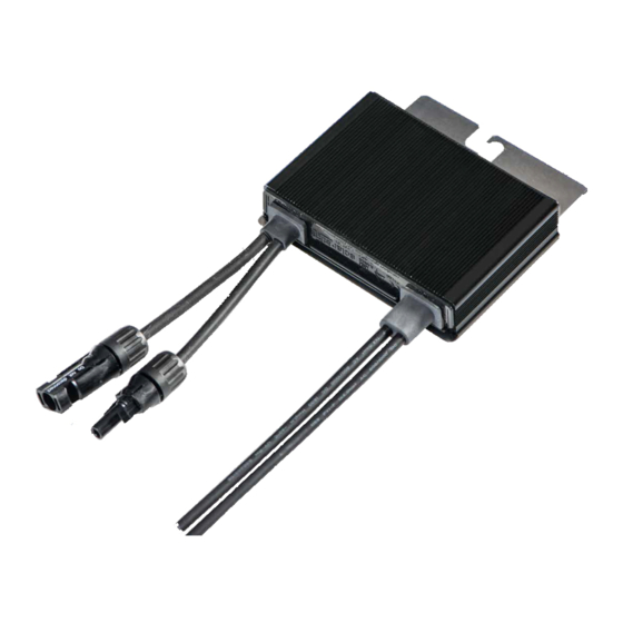
The images contained in this document are for illustrative purposes only and may vary depending on product models.
Connecting Power Optimizers to Modules
1
Mount the power optimizers in a shaded location near the PV modules, on the structure or racking to which the module is attached, using
the mounting holes. If possible, avoid mounting power optimizers in locations where they will be exposed to direct sunlight.
Make sure that each power optimizer is positioned within reach of each
module's cables. To allow proper heat dissipation, maintain a
1" /2.5 cm clearance distance between the power optimizer and other
surfaces.
2
Attach each power optimizer to the rack using the 5/16'' or 1/4'' bolts,
nuts and washers.
3
Use the following methods to ground the power optimizer:
For mounting on a grounded metal rail: Use the provided 5/16''
stainless steel grounding star washer between the railing and
the flat side of the mounting bracket.
The grounding washer should break through the anodize coating
of the railing to ensure low resistive connection. Apply torque of
9.5 N*m / 7 lb*ft.
For mounting on rails with sliding nut fasteners, or an un-grounded
structure (such as a wooden structure): Connect an equipment-grounding
conductor to the grounding terminal according to the instructions supplied
with the grounding terminals (grounding terminal kits are available from
SolarEdge). The grounding terminal accepts a wire size of 6-14 AWG, and must be
sized for equipment grounding per NEC 250.122 requirements. Tighten the screws
connecting the power optimizer to the frame and the grounding terminal screw.
Apply torque of 9.5 N*m / 7 lb*ft.
4
To benefit from the physical mapping of the installation in the SolarEdge
Monitoring Portal, record each power optimizer's serial number and
location: Peel off its removable barcode sticker and stick it on the mapping
template, or scan the barcode with the SolarEdge iPhone Site Mapper app.
Upload the map to the SolarEdge website, using the site registration form.
5
Connect the Plus (+) output connector of the module to the Plus (+) input
connector of the power optimizer.
6
Connect the Minus (-) output connector of the module to the Minus (-)
input connector of the power optimizer.
Connecting Power Optimizers in a String
1
Connect the power optimizer outputs in series: Connect the Minus (-) output connector of the string's first power optimizer to the Plus (+)
output connector of the string's second power optimizer. Connect the rest of the
optimizers in the string in the same way.
The minimum and maximum string length should be according to the
power optimizer datasheet.
Strings DO NOT have to be of equal length.
2
Verify proper connection of power optimizers: Before the inverter is turned ON,
each power optimizer produces 1V safety-voltage. Use a voltmeter to verify it for
each string using a voltmeter. The voltage on a string is the number of modules
multiplied by 1V, with a deviation of 10mV per module. Make sure the modules
are exposed to sunlight during this process.
NOTE:
If several strings are connected in parallel, verify voltage for each string separately
Star washer
Optional grounding
terminal
-
Output
+
1
Mounting Bracket
+
Input
-
Connect to module
Advertisement
Table of Contents

Related Manuals for SolarEdge P300


Summary of Contents for SolarEdge P300
- Page 1 For full installation and safety details, you must refer to the SolarEdge Installation Guide. Make sure you read, fully understand and follow the detailed instructions in the SolarEdge Installation Guide prior to each installation. Failure to do so could result in injury or loss of life and damage or destruction of the equipment.
-
Page 2: Installing The Inverter
Installing the Inverter Make sure that the inverter ON/OFF switch at the bottom of the inverter is switched OFF before and during the installation, and that the AC circuit breaker is OFF. Use a 5mm Allen key to open the AC/DC Safety Switch cover screws and remove the cover. Loosen these screws Open the required knockout pair (bottom, back or sides of the enclosure, sized ¾'' or 1'') according to the conduits used in the installation. -
Page 3: Connecting The Strings And The Ac To The Safety Switch
Switch bracket Connecting the Strings and the AC to the Safety Switch An example of the Safety Switch connections is shown below. . For more information, refer to the note in the device and to the SolarEdge Installation Guide. DC side... -
Page 4: Connecting The Strings
Three phase inverter For AC/DC Safety Switch: - Connect the Ground and Neutral wires to the terminal blocks in the AC side of the switch. Connect the line wires to the appropriate connectors according to the label located in the switch. ... -
Page 5: Inverter Interfaces
P-OK: Specifies the number of properly connected power optimizers. S-OK: Indicates the status of the connection to the SolarEdge monitoring portal (if connected). WARNING! Before proceeding to the next step, make sure that the cover is closed! High DC Voltage will be present in the inverter following the next step! Avant d’entamer la prochaine étape, assurez vous que le couvercle est fermé... -
Page 6: Pairing Power Optimizers To The Inverter
Pairing Power Optimizers to the Inverter Verify that the ON/OFF switch at the bottom of the inverter is OFF. Press and hold down the inverter LCD button for about 10 seconds. The following message is displayed: K e e p h o l d i n g b u t t o n f o r... -
Page 7: Creating An Rs485 Connection
The switch is located on the communication board and is marked SW7. To connect to the server, designate a single inverter as the connection point between the RS485 bus and the SolarEdge monitoring portal. This inverter will serve as the master inverter. Connect the master to the SolarEdge monitoring portal via one of the communication options.