Table of Contents
Advertisement
SERVICE MANUAL
Ver. 1.0 2008.01
SPECIFICATIONS
General
Type
One-point stereo (employing the Mid-side stereo
system), electret condenser microphone
Microphone cord
4mm diameter, two core-shielded OFC (Oxygen-free
copper) cord with Canon XLR-5-12C type connector
and gold plated L-shaped stereo miniplug
1
Stand screw
PF
/
screw
2
Approx. 40 × 183mm (diameter × length) (1
Dimensions
in.), projecting parts and controls not included.
Mass
Approx. 330 g (11.7 oz.) including battery and cord
Supplied accessories Wind screen (1)
Microphone holder (PF
Microphone stand (1)
Carrying case (1)
Performance
Frequency respone
50 – 18,000 Hz
Unidirectional × 2 (Directive angel: 90
Directivity
(switchable)
Output impedance
600 ohm ± 30% unbalanced
°)
Sensitivity (directive angle 120
Open circuit output voltage
Effective output level
Difference between L and R channel sensitivity: Less
than 3 dB
Power requirements Normal operating voltage: 1.5 V , R6 (Size AA)
battery
Minimum operating voltage: 1.1V , R6 (Size AA)
battery
Battery life: Approx. 200 hours with Sony R6P (SR)
battery
Maximum sound pressure level input
More than 120 dB
Dynamic range
More than 95 dB
Operating temperature range
°C – 40°C (32°F – 104°F)
0
∗1 0 dB = 1 v / Pa, 1,000 Hz (1 Pa = 10 μbar = 94 dB
∗2 0 dBm = 1 mW / Pa, 1,000 Hz
∗3 1% wave distortion at 1,000 Hz. (0 dB
Design and specifi cations are subject to change without notice.
Sony Corporation
9-887-969-01
2008A04-1
Audio Business Group
©
2008.01
Published by Sony Techno Create Corporation
ECM-957PRO
× 7
5
1
/
/
8
1
/
screw) (1)
2
° or 120°)
∗ 1
: –37
± 3 dB
∗ 2
: –40.8
± 3 dBm
∗ 3
SPL
)
SPL
= 2 × 10
3
Pa)
SPL
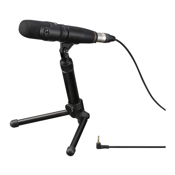
This microphone is suitable for use in a variety of situations such as at
concerts or conferences with digital recording equipment (Sony DAT, MD,
NT (Digital Microcorder) ICD, etc.).
• The turning capsule function allows both vertical and horizontal
sound pick-up.
• The Mid-Side Stereo System provides a natural sound pick up,
delivering a stereo sound image with superb clarity.
4
• The directive angle (between left and right channels) can be set
to
° or 120° according to the sound source.
90
Notes on chip component replacement
• Never reuse a disconnected chip component.
• Notice that the minus side of a tantalum capacitor may be dam-
aged by heat.
ELECTRET CONDENSER
STEREO MICROPHONE
US Model
Canadian Model
FEATURES
Advertisement
Table of Contents

Subscribe to Our Youtube Channel
Related Manuals for Sony ECM-957PRO


Summary of Contents for Sony ECM-957PRO
- Page 1 SPECIFICATIONS FEATURES General This microphone is suitable for use in a variety of situations such as at concerts or conferences with digital recording equipment (Sony DAT, MD, Type One-point stereo (employing the Mid-side stereo NT (Digital Microcorder) ICD, etc.). system), electret condenser microphone •...
-
Page 2: Section 1 General
ECM-957PRO SECTION 1 GENERAL This section is extracted from instruction manual. -
Page 3: Section 2 Disassembly
ECM-957PRO SECTION 2 DISASSEMBLY • This set can be disassembled in the order shown below. 2-1. GRIP ASSY (Page 3) 2-2. GRILL ASSY (Page 4) 2-3. CHASSIS (Page 4) 2-4. AMP BOARD (Page 5) Note: Follow the disassembly procedure in the numerical order shown below. - Page 4 ECM-957PRO 2-2. GRILL ASSY joint (2) screw screw (+B 1.4 × 6) rotary knob joint (2) screw screw (+B 1.4 × 6) rotary knob grill assy 2-3. CHASSIS two screws (+K 2 × 4) chassis two screws (+K 2 × 4)
-
Page 5: Amp Board
ECM-957PRO 2-4. AMP BOARD Remove the twenty five solders. two screws black green white (+K 2 × 4) ground plate blue yellow white black black black yellow AMP board white brown black blue green white yellow black blue... - Page 6 ECM-957PRO MEMO...
- Page 7 ECM-957PRO SECTION 3 DIAGRAMS 3-1. PRINTED WIRING BOARD • : Uses unleaded solder. For Printed Wiring Boards. SIDE ASSY ROTARY FRAME ASSY Note: MIC2 MIC1 • X : Parts extracted from the component side. (MID) (SIDE) • Y : parts extracted from the conductor side.
- Page 8 ECM-957PRO 3-2. SCHEMATIC DIAGRAM MIC1 S1-2 MIC2 S1-1 For Schematic Diagrams. Note: • All capacitors are in μF unless otherwise noted. (p: pF) 50 WV or less are not indicated except for electrolytics and tantalums. • All resistors are in Ω and W or less unless otherwise specifi...
-
Page 9: Exploded Views
ECM-957PRO SECTION 4 EXPLODED VIEWS Note: • The mechanical parts with no reference • -XX and -X mean standardized parts, so number in the exploded views are not sup- The components identifi ed by mark 0 they may have some difference from the plied. -
Page 10: Frame Section
ECM-957PRO 4-2. FRAME SECTION not supplied not supplied (Q1) not supplied not supplied (MIC2) not supplied not supplied not supplied (Q2) not supplied not supplied not supplied (MIC1) Ref. No. Part No. Description Remark Ref. No. Part No. Description Remark... -
Page 11: Section 5 Electrical Parts List
ECM-957PRO SECTION 5 ELECTRICAL PARTS LIST Note: • RESISTORS • Due to standardization, replacements in All resistors are in ohms. When indicating parts by reference num- the parts list may be different from the METAL: Metal-fi lm resistor. ber, please include the board name. -
Page 12: Revision History
ECM-957PRO REVISION HISTORY Checking the version allows you to jump to the revised page. Also, clicking the version at the top of the revised page allows you to jump to the next revised page. Ver. Date Description of Revision 2008.01...
Need help?
Do you have a question about the ECM-957PRO and is the answer not in the manual?
Questions and answers