Table of Contents
Advertisement
Quick Links
QQ
3 7 63 1515 0
TE
L 13942296513
www
.
http://www.xiaoyu163.com
SERVICE MANUAL
MINIDISC RECORDER
MODEL
MINIDISC RECORDER
DISC LOADIING MECHANISM
INPUT
STANDBY / ON
STANDBY
DISPLAY
MDT
MGT, MGR
SAFETY-RELATED COMPONENT
WARNING!!
COMPONENTS IDENTIFIED BY MARK
SCHEMATIC DIAGRAM AND IN THE PARTS LIST ARE
CRITICAL FOR RISK OF FIRE AND ELECTRIC SHOCK.
REPLACE THESE COMPONENTS WITH ONKYO
PARTS WHOSE PART NUMBERS APPEAR AS SHOWN
IN THIS MANUAL.
MAKE LEAKAGE-CURRENT OR RESISTANCE
MEASUREMENTS TO DETERMINE THAT EXPOSED
PARTS ARE ACCEPTABLY INSULATED FROM THE
SUPPLY CIRCUIT BEFORE RETURNING THE
APPLIANCE TO THE CUSTOMER.
x
ao
u163
y
i
http://www.xiaoyu163.com
2 9
8
MD-101A
MULTI JOG
EDIT / NO YES
CD
REC MODE
DUBBING
REC
PUSH TO ENTER
-
101 A
MD
Q Q
3
6 7
1 3
1 5
Silver models
120V AC, 60Hz
220-230V AC, 50/60Hz
ON THE
co
.
9 4
2 8
Ref. No. 3703
STANDBY/ON
EJECT
PLAY MODE
CONTINUE
RANDOM
MEMORY
A
B
C
D
E
1
2
3
4
5
F
G
H
I
J
8
9
6
7
10
K
L
M
N
O
13
14
11
12
15
P
Q
R
S
T
16
18
19
17
20
U
V
W
X
Y
21
22
23
24
25
.
,
Z
REPEAT
A-B
A.SPACE
M.SCAN
>25
/
?
!
(
)
REC
CLEAR
ENTER
SCROLL
DISPLAY
NAME
RC- 475 MD
REMOTE
CONTROLLER
RC-475MD
0 5
8
2 9
9 4
2 8
m
MD-101A
9 9
112001
9 9
Advertisement
Table of Contents

Subscribe to Our Youtube Channel
Related Manuals for Onkyo MD-101A


Summary of Contents for Onkyo MD-101A
- Page 1 COMPONENTS IDENTIFIED BY MARK ON THE SCHEMATIC DIAGRAM AND IN THE PARTS LIST ARE CRITICAL FOR RISK OF FIRE AND ELECTRIC SHOCK. REPLACE THESE COMPONENTS WITH ONKYO PARTS WHOSE PART NUMBERS APPEAR AS SHOWN IN THIS MANUAL. MAKE LEAKAGE-CURRENT OR RESISTANCE...
-
Page 2: Specifications
MD-101A 3 7 63 1515 0 SPECIFICATIONS System Number of channels MiniDisc digital audio system 2 (stereo) Recording system Frequency response Magnetic field modulation overwrite system 10 Hz - 20 kHz ( 0.5 dB) Signal read out system Signal to noise ratio... -
Page 3: Display Messages
MD-101A 3 7 63 1515 0 DISPLAY MESSAGES Message Meaning Auto Space This message appears during the track intervals when A. Space is turned on. Blank Disc A new recordable MD or a recordable MD without disc or track names is inserted. -
Page 4: Protection Of Eyes From Laser Beam During Servicing
MD-101A 3 7 63 1515 0 SERVICE PROCEDURES PROTECTION OF EYES FROM LASER BEAM DURING SERVICING This set employs a laser. Therefore, be sure to follow Laser Diode Properties carefully the instructions below when servicing. Material: GaAS/GaAlAs Wavelength: 780 nm... -
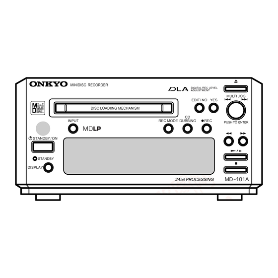
Page 5: Panel Views
MD-101A 3 7 63 1515 0 PANEL VIEWS-1 FRONT PANEL Ventilation CD DUBBING holes button Disc slot INPUT EDIT/NO button button REC MODE Remote control REC button ( REC) button sensor YES button Eject button STANDBY/ON button MULTI JOG knob... - Page 6 Amplifier DAT deck, etc. Connection to AC outlet Connecting to the Amplifier (UNSWITCHED) Connect the MD-101A to the MD (or TAPE) L 13942296513 The power cord of another unit can be connected jacks of your amplifier. to this outlet. Connecting to the Digital Input...
-
Page 7: Remote Controller
MD-101A 3 7 63 1515 0 REMOTE CONTROLLER RC-475MD (supplied) STANDBY/ON button STANDBY/ ON EJECT EJECT button A-B repeat button PLAY MODE CONTINUE RANDOM MEMORY PLAY MODE buttons Uppercase and CONTINUE buttons lower case letters, RANDOM button symbols, and... -
Page 8: Exploded View
MD-101A 3 7 6 3 1 5 1 5 0 EXPLODED VIEW P702 P901 F901 L 1 3 9 4 2 2 9 6 5 1 3 P801 E801 T901 u 1 6 3 http://www.xiaoyu163.com... -
Page 9: Exploded View Parts List
MD-101A 3 7 6 3 1 5 1 5 0 EXPLODED VIEW PARTS LIST REF NO. PART NO. DESCRIPTION REF NO. PART NO. DESCRIPTION 27111252 Front bracket E801 260208 Binder, UL AS-CEE or P901 253336VOL or 3TTB+8B, Self tapping screw... - Page 10 MD-101A 3 7 63 1515 0 EXPLODED VIEWS OF MECHANISM-1 MD MECHANISM: KMK-260EDN L 13942296513 SW1-SW4 The mechanical parts with no part number PARTS LIST in the exploded views are not supplied. REF NO. PART NO. DESCRIPTION REF NO.
-
Page 11: Parts List
MD-101A 3 7 63 1515 0 EXPLODED VIEW OF MECHANISM-2 MD MECHANISM: KMK-260EDN L 13942296513 The mechanical parts with no part number PARTS LIST in the exploded views are not supplied. REF. NO. PART NO. DESCRIPTION 3348-998-51 Pan tapping screw(M1.4×3.5) - Page 12 MD-101A 3 7 63 1515 0 EXPLODED VIEWS OF MECHANISM-3 MD MECHANISM: KMK-260EDN MD Mount view Side-A IC121 IC171 IC125 Test point-A IC201 for adjustment D101 I+3V IC101 AGND L 13942296513 Side-B Q162 CN103 Q102 Test point (No use)
- Page 13 MD-101A 3 7 63 1515 0 EXPLODED VIEWS OF MECHANISM-4 MD MECHANISM: KMK-260EDN L-SW PC BOARD VIEW D-SW PC BOARD VIEW CN108 CN107 The mechanical parts with no part number PARTS LIST (MD mount section) in the exploded views are not supplied.
-
Page 14: Block Diagram
MD-101A 3 7 6 3 1 5 1 5 0 BLOCK DIAGRAM AC OUTLET T901 POWER TRANSFORMER D901 Q801 FL TUBE L901 WITH DRIVER IC Q901 +36V(Q801,Q802) HCA-14SS02T D902,D913 RESET(Q701) Q711 POFF(Q701) AC IN BMR0101 Q703,Q704 M+5V(MD MECHA) Q905... -
Page 15: Schematic Diagrams
MD-101A 3 7 63 1515 0 SCHEMATIC DIAGRAMS N O T E T H E C O M R E P L A C E . V O L T A G E Q801 . E L E C T R O HCA-14SS02T . - Page 16 MD-101A 3 7 63 1515 0 A R E C R I T I C A L F O R S A F E T Y . C O M P O N E N T S I D E N T F I E D...
- Page 17 MD-101A 3 7 63 1515 0 PC BOARD CONNECTION DIAGRAM ANALOG DIGITAL INPUT REMOTE INPUT OUTPUT CONTROL NAETC-7302 AC outlet ROUT NAAR-7298 PC board LOUT Main circuit PC board -11V P904 +10.2V AC IN NADG-7299 Microprocessor +3.3V PC board -5.0V...
-
Page 18: Display Pc Board
MD-101A 3 7 63 1515 0 PRINTED CIRCUIT BOARD VIEWS-1 DISPLAY PC BOARD (NADIS-7301) J205 Component side P801B J204 S807 J200 S810 S811 S812 NCDIS-7301 Q803 S807 25137301 S805 J203 X702 Q801 INPUT LP_MODE CD_DUB J198 J189 J197 STANBY/ON... - Page 19 MD-101A 3 7 63 1515 0 PRINTED CIRCUIT BOARD VIEWS-2 MICROPROCESSOR PC BOARD (NADG-7299) Component side Soldering side E851 C212 C211 R215 J159 J157 J156 R222 R913 R221 J153 C213 J152 D201 J154 J151 J150 J149 J148 J147 J146...
-
Page 20: Power Supply Pc Board
MD-101A 3 7 63 1515 0 PRINTED CIRCUIT BOARD VIEWS-3 POWER SUPPLY PC BOARD (NAAR-7298) Component side C913 P402 C914 D901 C905 C913 C914 J903 C906 R105 J914 J902 J910 J905 J917 J908 J904 J901 J922 Q904 C918 J923... -
Page 21: Printed Circuit Board Parts List
MD-101A 3 7 63 1515 0 PRINTED CIRCUIT BOARD PARTS LIST-1 MAIN CIRCUIT PC BOARD (NAAR-7298-1B/1C/1D) CIRCUIT NO. PART NO. DESCRIPTION Q101 22240608R1 NJM2100M Q401,Q402 24120083 or GP1FA550RZ 24120086 GP1FA551RZ Q403 222740046R2TO TC74HCU04F Q902,Q906 22278005ENE MPC29M05HF Q905 22278005DNE MPC2905HF... - Page 22 MD-101A 3 7 63 1515 0 PRINTED CIRCUIT BOARD PARTS LIST-2 MICROPROCESSOR PC BOARD (NADG-7299-1B/1C/1D) CIRCUIT NO. PART NO. DESCRIPTION Q203,Q204,Q709 22241383R2 NJM4565M-D Q701 22241670R3 MPD780056GC-038-8BT Q702 222740046R2TO TC74HCuF04F Q711 22241210 BMR-0101D Transistors Q201,Q202 2211705 or 2SD655-E or Q205,Q206...
- Page 23 MD-101A 3 7 63 1515 0 PRINTED CIRCUIT BOARD PARTS LIST-3 POWER SUPPLY PC BOARD (NAPS-7300-1B/1C/1D) CIRCUIT NO. PART NO. DESCRIPTION Coil L901 231287 NCH-3567, Choke coil Capacitors C901,C902 3300030 DE1307E472M-KH, IS <GT,GR> 3300031 DE1607F103M-KH, IS <DT> Plug P901A...
- Page 24 MD-101A 3 7 63 1515 0 FL TUBE VIEW Q801:HCA-14SS02T ARTIST CD-RW SKIP ON FINALIZE 13Ga 13Gb 13Gc 13Gd 14Ga 14Gb 14Gc 14Gd (13G) (12G - 1G) -R W SKIP ON 25 26 11 12 13 14 15 ARTIST...
- Page 25 MD-101A 3 7 6 3 1 5 1 5 0 MICROPROCESSOR CONNECTION DIAGRAM Q101(1/2) BUFFER AMP P101 L IN MD MECHANISM R IN Q203(2/2) INPUT Q203(1/2) KMK-260EDN L OUT ANALOG MUTE R OUT Q201 OUTPUT Q205 D IN1 +3.3 V +4.8 V...
- Page 26 MD-101A 3 7 6 3 1 5 1 5 0 MICROPROCESSOR TERMINAL DESCRIPTIONS-1 Q701: MPD780056GC-033-8BT (MAIN MICROPROCESSOR) PIN NO. FUNCTION DESCRIPTION PIN NO. FUNCTION DESCRIPTION Not used. (Connect to ground) METEST The input terminal for test mode setup of MD mechanism.
- Page 27 MD-101A 3 7 6 3 1 5 1 5 0 MICROPROCESSOR TERMINAL DESCRIPTIONS-2 Q802: TMP87C447uF-3GC (SUB MICROPROCESSOR) PIN NO. FUNCTION DESCRIPTION PIN NO. FUNCTION DESCRIPTION SUB_CLK Input terminal of serial data clock from main microprocessor. NOT USED Not used. (Connect to ground) NOT USED Not used.
-
Page 28: Adjustment Procedures
MD-101A 3 7 63 1515 0 ADJUSTMENT PROCEDURES-1 The necessity for adjustment necessary unnecessary The exchanged parts Adjustment item Parts on MD REMARKS Mechanical Pickup unit mount, parts and Motors Adjustment of Temperature Compensation Offset Adjustment of laser power... - Page 29 MD-101A 3 7 63 1515 0 ADJUSTMENT PROCEDURES-2 Explanation in test mode Time chart 1. How to test mode to enter (1) Connect the power supply cord in the wall socket. push (2) While hold down the YES button, press the DISPLAY button at standby state.
- Page 30 MD-101A 3 7 63 1515 0 ADJUSTMENT PROCEDURES-3 Preparation of adjustment 1. Make the extended JIG and connection. PC board Jumper wire Socket Part No.NCJIG-0J12 Part No.25052307 Connect to the MD mechanism Extended JIG (KIT) Part No.0J12 Flexible flat cable Part No.
- Page 31 MD-101A 3 7 63 1515 0 ADJUSTMENT PROCEDURES-4 The adjustment method Adjustment of temperature compensation value [NONE] (1) Perform circumference temperature in the 22 to 28 degrees state. (2) Adjust, after exchanging D101, and the temperature of this part turns into the same temperature as circumference temperature.
- Page 32 MD-101A 3 7 63 1515 0 ADJUSTMENT PROCEDURES-5 Adjustment of laser power [Preparation] (1) Connect digital volt meter to I+3V and IOP on Extended JIG. (2) Set the optical sensor to laser power meter. (3) Loading of the optical sensor to the unit.
- Page 33 MD-101A 3 7 63 1515 0 ADJUSTMENT PROCEDURES-6 Adjustment of traverse (EF balance) [Preparation] (1) Connect oscilloscope to TE and VC on Extended JIG. [NOTE] Do not connect the VC to the GND of the unit. (2) Loading the MO disk to the unit.
- Page 34 MD-101A 3 7 63 1515 0 ADJUSTMENT PROCEDURES-7 Check of the error rate by the high reflectance disk [Preparation] (1) Loading of the high reflectance disk to the unit. [Check] (1) Turns the JOG knob and select the CPLAY MOD E CP LAY MOD E (2) Press the JOG button .
- Page 35 MD-101A 3 7 63 1515 0 ADJUSTMENT PROCEDURES-8 Check of the error rate by the MO disk [Preparation] Make the continuation recording disk used for the check of the error rate. If the disk created by other sets is used, since the check with normal recording cannot be performed, please carry out self-recording reproduction with the same set.
- Page 36 MD-101A 3 7 63 1515 0 ADJUSTMENT PROCEDURES-9 Adjustment the focus bias When an error rate is worse than the standard value, perform this work. [Preparation] (1) Loading the continuation recording disk to the unit. [Adjustment] (1) Turns the JOG knob and select the C PLAY MODE CP LAY M ODE.
- Page 37 MD-101A 3 7 63 1515 0 ADJUSTMENT PROCEDURES-10 Check of focus bias When an error rate is worse than the standard value, perform this work. [Preparation] (1) Loading of the continuation recording disk to the unit. [Check] (1) Turns the JOG knob, and select the CPLAY MOD E CPLAY MODE.
-
Page 38: Packing View
MD-101A 3 7 63 1515 0 PACKING VIEW L 13942296513 PARTS LIST REF NO. PART NO. DESCRIPTION 29092023A Pad AS 29092023-1A Pad AS MANUFACTURED IN MALAYSIA 29053832 Carton <DT,GT> Carton <DT,GT> MADE IN JAPAN 29053832-1 29053833A Carton <GR> MANUFACTURED IN MALAYSIA 29053833-1A Carton <GR>... - Page 39 Sales & Product Planning Div. : 2-1, Nisshin-cho, Neyagawa-shi, OSAKA 572-8540, JAPAN Tel: 072-831-8111 Fax: 072-833-5222 ONKYO U.S.A. CORPORATION 18 Park Way, Upper Saddle River, N.J. 07458, U.S.A. Tel: 201-785-2600 Fax: 201-785-2650 E-mail: onkyo@onkyousa.com ONKYO EUROPE ELECTRONICS GmbH Industriestrasse 20, 82110 Germering, GERMANY Tel: 089-849-320 Fax: 089-849-3265 E-mail: info@onkyo.de...
Need help?
Do you have a question about the MD-101A and is the answer not in the manual?
Questions and answers