Sign In
Upload
Manuals
Brands
Gamatronic Manuals
UPS
PowerPlus RM 100
Gamatronic PowerPlus RM 100 Manuals
Manuals and User Guides for Gamatronic PowerPlus RM 100. We have
1
Gamatronic PowerPlus RM 100 manual available for free PDF download: User Manual
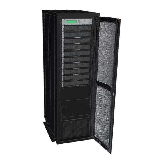
Gamatronic PowerPlus RM 100 User Manual (183 pages)
UPS SYSTEM 3X208 VAC, 10 KVA TO 100 KVA
Brand:
Gamatronic
| Category:
UPS
| Size: 6 MB
Table of Contents
Table of Contents
3
And Its Battery Cabinet )
15
Figure 1: Flanges for Securing the RM100 to the Ground
15
Figure 2: Remove the Flanges before Moving the RM100 with a Forklift
15
1 Moving the Power + Rm100 ( and Its Battery Cabinet)
16
2 Important Safety Instructions
16
Do's
16
Don'ts
17
Power + Rm100
17
3 Introduction to the Power Plus Rm100
19
POWER + Features
19
Figure 3: Main Subassemblies of the RM100
20
Ac and DC Fuses
21
Ac Input/Output Main Terminals
21
System Controller
21
UPS Module (10 Kva / 8 Kw)
21
Static Switch (ST/SW) Module
21
4 Battery
22
Connecting the Battery Cabinet to the UPS
24
Additional Considerations
24
Figure 4: Battery Cabinet
25
Figure 5: One Battery Box
26
Figure 6: One Battery Drawer
26
Figure 7: Battery Cabinet Wiring
27
Battery Replacement Instructions
28
5 Operating Modes
29
Normal Operation
29
Battery Operation
29
Bypass Operation
29
Maintenance Bypass Mode
30
6 User Interface
31
Control Panel
31
UPS Module Panel
31
Figure 8: Control Panel
31
Figure 9: UPS Module Panel
31
Static Switch Panel
32
Figure 10: Static Switch Panel
32
POWER + Control Screen
33
Load-Level Bar Graph
33
Figure 11: POWER+ Control Screen
33
Navigation and Operation Keypad
34
Figure 12: Navigation and Operation Keypad
34
Status Indicators
35
Figure 13: Status Indicators
35
Table 1: Status Indicators
35
Operation Buttons
36
Network Access Indicator
36
Figure 14: Network Access Indicator
36
Table 2: Operation Buttons
36
Table 3: Network Access Indication
36
POWER + Operation Modes
37
6.9.1 Normal Operation
37
6.9.2 Battery Operation
37
Figure 15: POWER+ Control Screen in Normal Operation
37
Figure 16: Normal Operation Indication
37
Figure 17: AC Power Failure
37
Bypass Operation (Automatic)
38
Bypass Operation (Manual)
38
Emergency Power off - EPO (Manual)
38
Figure 18: AC Power Failure Indication
38
Figure 19: UPS in Bypass Mode
38
Figure 20: Red Alarm Flashing
38
7 System Installation
39
7.1 Cabling
39
Figure 21: RM100 3X208 V, Rear View
40
Figure 22: Cable Entry from the Top or Bottom of UPS Cabinet
41
Figure 23: Connection Diagram for 3-3 Configuration
42
The Power+ Always Requires a Neutral Line
43
7.2.1 a 4-Pole Switch Might Disconnect the Neutral Line
43
Figure 24: Wrong Way to Connect UPS with Four-Pole Switch
45
Figure 25: Acceptable Connection for Grounded Generator and 4-Pole Switch
46
Figure 26: Preferred Generator (Neutralized) and Connection (3-Pole)
47
Figure 27: Ground Connections on Theups Cabinet Roof
48
Ground Connections
48
Figure 28: Crimp -Type Cable Shoes Recommended for All Ground Cables
49
Figure 29: Ground Studs on UPS Cabinet Roof, View from below
49
Table 4: Key to Figure 29
49
Figure 30: Ground Studs on Inside of Batt. Cabinet Roof
50
Figure 31: Ground Bus Bar at Base of UPS Rear
50
Table 5: Key to Figure 30 and Figure 31 above
50
Over-Current Protection
51
Ac Wiring
51
Table 6: Required Over-Current Protection
51
DC Wiring
52
Fuses
53
Ac Input Fuses
53
Figure 32: Ac Input Fuses (100 Kva Model)
53
DC Distribution Fuses
54
Figure 33: DC Distribution Fuse Assignment (100 Kva)
54
Special Terminal Connections
55
Load on Bypass Alarm
55
Battery Trip Coil
55
Figure 34: Special Purpose Terminal Connections
55
Emergency Power-Off
56
Dry Contacts
57
Figure 35: Dry Contacts on Rear of Controller
57
Inspections to be Performed Prior to Installation
58
Table 7: Pre-Installation Inspections
58
Installation Procedure
59
Table 8: Installation Procedure
59
Figure 36: Start-Up Screen 1
60
Figure 37: Start-Up Screen 2
60
Figure 38: Start-Up Screen 3
60
First-Time Startup
60
Figure 39: Start-Up Screen 4
61
Figure 40: Default Screen, with no Load, for 3-Phase Output
61
Figure 41: Default Screen, with no Load, for 2-Phase Output
61
Figure 42: Normal Display, System under Load (3-Phase Output)
61
Figure 43: Normal Display, System under Load (2-Phase Output)
61
Checks to be Performed Following Initial Startup
63
Table 9: Checks after Initial Startup
63
Connection Diagram
64
Figure 44: Connection Diagram (for Completion by the Customer)
64
7.13 Configuration
65
Check Configured Modules
65
Figure 45: Main Menu
65
Figure 46: Password Access
65
Figure 47: Setup Menu
65
Figure 48: Service Menu
66
Figure 49: Configure Menu
66
Figure 50: # of Upss (Total)
66
Figure 51: # of Upss (Redundancy)
66
Check Total Ampere-Hours
67
Figure 52: Battery Status
67
Figure 53: Battery Capacity
67
Figure 54: Set Battery Capacity
67
Set Date and Time and Serial Number
68
Define the IP Address of the Power
68
Figure 55: Date and Time
68
Figure 56: Site Number
68
Figure 57: Network Menu
68
Figure 58: IP Address
69
Figure 59: Gateway
69
Figure 60: Network Menu
69
7.14 Testing
70
Blackout Test
70
Cold Start
70
Test under Load
70
Check IP Communication with Controller
71
Figure 61: Main Screen of the Power+ Web Interface
71
Test Wing Option
72
Figure 62: Login Screen of Built-In Web Server
72
Figure 63: SMS Screen
72
8 Power + Routine Start up
73
Start-Up after Shutdown
73
Figure 64: Main Screen after a Power Shutdown
73
Figure 65: Main Screen after a Power Shutdown Indication
73
Figure 66: Main Screen at Power-Up
73
Figure 67: Normal Operation Indication
74
Figure 68: Main Screen Results
74
POWER + Shutdown (Switching to Bypass)
75
Figure 69: Main Screen - Switching to Bypass
75
Figure 70: Bypass Indication
75
POWER + Total Shutdown (no Ac Output)
76
Figure 71: Main Screen - Total Shutdown
76
Figure 72: UPS off Indication
76
9 Power + Control Panel
77
Figure 73: Control Panel
77
Quick-Reference Summary of Power+ Menu Functions
78
Figure 74: Main Menu
78
Figure 75: System Menu
79
Figure 76: Battery Menu
79
Figure 77: Setup Menu
79
Figure 78: Static Switch Menu
79
Figure 79: Alarm Set Sub-Menu
80
Figure 80: Module Configuration Sub-Menu
80
Figure 81: Battery Menu
80
Figure 82: Service Sub-Menu
81
Figure 83: Configure Sub-Sub-Menu
82
Figure 84: Silicon Sub-Menu
82
10 Ower Menu Functions in Detail
83
10.1 Main Menu
83
Figure 85: Main Menu
83
Table 10: Main Menu Options
83
10.2 "System" Option
84
Figure 86: Main Menu Option 1 ("System")
84
Figure 87: System DC Voltages
84
Figure 88: Output Power Factor 1
85
Figure 89: Input Power Factor 1
85
Figure 90: Overall Phase Voltages/Currents
85
Figure 91: Elapsed Time
85
Figure 92: Jumper Settings WITHOUT Remote Panel
86
Figure 93: Jumper Settings with Remote Panel
86
Figure 94: Internal Controller Voltages
86
Figure 95: Battery Parameters
86
Figure 96: Fuse Status
87
Figure 97: Communication with Inverter - Transmit
87
Figure 98: Communication with Inverter - Receive
87
10.3 "UPS Module" Option
88
Figure 99: Main Menu Option 2 ("UPS Module")
88
Figure 100: LCD Panel - Select a UPS
88
Figure 101: Module Phase Voltages/Currents
89
Figure 102: Battery Voltages & Technician Parameters
89
10.4 "Self-Test" Option
90
Figure 103: Main Menu Option 3 ("Self Test")
90
Figure 104: Result Screen from Self-Test
90
10.5 "History" (Logs) Option
91
Figure 105: Main Menu Option 4 ("History")
91
Figure 106: History Logs
91
Figure 107: History Log Scroll
92
Table 11: Log Messages
93
Table 12: Interpreting the Static Switch Transfer Code (LOADBP)
94
10.6 "Battery" Option
95
Figure 108: Main Menu Option 5 ("Battery")
95
Figure 109: Battery Status
95
Figure 110: Battery Equalizing
96
Figure 111: Time Left
96
Figure 112: Last Test
96
Figure 113: Battery Current
96
10.7 "Alarm" Option
97
Figure 114: Battery Capacity
97
Figure 115: Battery Current Limit
97
Figure 116: Main Menu Option 6 ("Alarm")
98
Figure 117: Alarms 01-12
98
Figure 118: Alarms 13-24
98
Figure 119: Alarms 25-32
98
10.8 "Setup - Alarm Set" Option
99
Figure 120: Main Menu Option 7 ("Setup - Alarm Set")
99
Figure 121: Level 1 Password Access
99
Figure 122: Setup Menu
100
Figure 123: Alarm Setup Menu
100
Figure 124: Ac Alarms Menu
100
Figure 125: Set Ac Alarm Voltage Levels
100
Setting Ac Voltage Alarms
100
Figure 126: Ac Alarms Menu
101
Figure 127: Set Ac Voltage Hysteresis
101
Figure 128: Alarm Set Menu
101
Figure 129: Battery Floating Charge Alarm Setup Menu
101
Setting Battery Floating Voltage Alarm
101
Figure 130: Set BATEND
102
Figure 131: Battery Floating Charge Alarm Setup Menu
102
Figure 132: Set BATLOW
102
Figure 133: Battery Floating Charge Alarm Setup Menu
102
Figure 134: Set BAT-HI
102
Figure 135: Alarm Set Menu
103
Figure 136: Over/Under Temperature Menu
103
Figure 137: Set Battery Maximum Temperature Alarm
103
Figure 138: Over/Under Temperature Menu
103
Setting Battery Over/Under Temperature Alarms
103
Figure 139: Set Battery Minimum Temperature Alarm
104
Figure 140: Alarm Set Menu
104
Figure 141: Set the Integration Factor Alarm
104
Setting Battery Integration Alarm
104
10.9 "Setup - Module Conf." Option
105
Figure 142: Main Menu Option 7 ("Setup - Module Conf.")
105
Figure 143: Level 1 Password Access
105
Figure 144: Setup Menu
106
Figure 145: Module Config. Setup Menu
106
Figure 146: Module Config. Setup Menu
106
Figure 147: Setting the Module/S Frequency
106
Setting Module/S Frequency
106
Setting Number of Phases
106
Figure 148: Module Config. Setup Menu
107
Figure 149: Setting the Module/S Voltage
107
Figure 150: Module Config. Setup Menu
107
Figure 151: Updating the Module/S Voltage/Frequency/Phase
107
Setting Module/S Voltage
107
Update Voltage/Frequency/Phase
107
Figure 152: Module Config. Setup Menu
108
Figure 153: Select a Phase to Adjust
108
Figure 154: Select a Module to Adjust
108
Figure 155: Select a Value to Adjust
108
Output Adjustment
108
Calibrating DC Voltage
109
Figure 156: Module Config. Setup Menu
109
Figure 157: Select the Frequency Limits
109
Figure 158: Module Config. Setup Menu
109
Figure 159: Calibrate Positive or Negative Voltage
109
Setting Frequency Limits
109
Calibrating AC Voltage
110
Figure 160: Enter Measured Value
110
Figure 161: Module Config. Setup Menu
110
Figure 162: Calibrate INPUT or OUTPUT Voltage
110
Figure 163: Enter Measured Value
110
10.10 "Setup - Battery" Option
111
Figure 164: Main Menu Option 7 ("Setup - Battery")
111
Figure 165: Level 1 Password Access
112
Figure 166: Setup Menu
112
Figure 167: Battery Setup Menu
112
Figure 168: Set Battery Test Voltage
112
Setting Battery Test Voltage
112
Figure 169: Battery Setup Menu
113
Figure 170: Set Battery Test Voltage Alarm
113
Setting Battery Test Voltage Alarm
113
Figure 171: Battery Setup Menu
114
Figure 172: Current Limit Setup Menu
114
Figure 173: Current Limit Indication for (Each) Battery
114
Figure 174: Set Current Limit for (Each) Battery
114
Setting Battery Current Limit
114
Enable/Disable Battery Current Limit
115
Figure 175: Battery Setup Menu
115
Figure 176: Current Limit Setup Menu
115
Figure 177: Enable/Disable Current Limit
115
Figure 178: Battery Setup Menu
116
Figure 179: Temperature Compensation Setup Menu
116
Figure 180: Set Temperature Compensation
116
Setting Temperature Compensation
116
Figure 181: Battery Setup Menu
117
Figure 182: Enable/Disable Temperature Compensation
117
Figure 183: Select Set ABSOLUTE Max & Min Voltages
117
Setting Absolute Maximum and Minimum Voltages
117
Setting Disable Temperature Compensation
117
Figure 184: Select Set Absolute Minimum Output Voltage
118
Figure 185: Set Absolute Minimum Output Voltage When Compensating
118
Figure 186: Select Set Absolute Maximum Output Voltage
118
Figure 187: Set Absolute Maximum Output Voltage When Compensating
118
Gamatronic Electronic Industries Ltd
119
Activating the Battery Test
119
Figure 188: Battery Setup Menu
119
Figure 189: Select Activate Battery Test
119
Figure 190: Activate Battery Test
119
Figure 191: Battery Setup Menu
119
Setting the Automatic Battery Test Period
119
10.10.10 Setting the Automatic Battery Test Top Time
120
Figure 192: Select Set Auto Battery Test Period
120
Figure 193: Set Battery Test Period
120
Figure 194: Battery Setup Menu
120
Figure 195: Select Set Auto Battery Test Top Time
120
Figure 196: Set Battery Test Top Time
121
Figure 197: Battery Setup Menu
121
Figure 198: Select Set Capacity of Battery #1
121
Figure 199: Set Battery Capacity
121
Setting the N Battery Capacity
121
10.10.12 Activating 'Auto' Test
122
10.10.13 Enabling/Disabling Options
122
Figure 200: Battery Setup Menu
122
Figure 201: Activated 'Auto' Test
122
Figure 202: Battery Setup Menu
122
Figure 203: Enable/Disable Shutdown by Long AC Failure
123
Setup - Charge, Time, Site, and Password Options
124
Figure 204: Main Menu Option 7 ("Setup - Charge, Time, Site, & Password")
124
Figure 205: Level 1 Password Access
124
Figure 206: Setup Menu
125
Figure 207: Charge Setup Menu
125
Figure 208: Set Floating Charge
125
Setting the Floating Charge
125
Figure 209: Setup Menu
126
Figure 210: Set Date and Time
126
Figure 211: Setup Menu
126
Figure 212: Set Site Number
126
Setting the Site Number
126
Setting the Time
126
Changing the Password
127
Figure 213: Setup Menu
127
Figure 214: Change Password
127
10.12 "Setup - "Service" Option
128
Figure 215: Main Menu Option 7 ("Setup - Service") 1/2
128
Figure 216: Main Menu Option 7 ("Setup - Service") 2/2
129
Figure 217: Level 1 Password Access
129
Figure 218: Setup Menu
130
Figure 219: Service Menu
130
Figure 220: Set Upss
130
Figure 221: Service Menu
130
Setting Upss
130
Testing Dry Output Relays
130
Configuring the UPS
131
10.12.3.1 Number of Redundant Upss
131
Figure 222: Set Upss
131
Figure 223: Service Menu
131
Figure 224: Service > Configure Menu
131
Figure 225: Set Number of Redundant Upss
131
10.12.3.2 Total Number of Upss
132
10.12.3.3 Total Number of Batteries
132
Figure 226: Service > Configure Menu
132
Figure 227: Set Total Number of Upss
132
Figure 228: Service > Configure Menu
132
Figure 229: Set Total Number of Batteries
132
10.12.3.4 Setting up the Static Switch
133
Figure 230: Service > Configure Menu
133
Figure 231: Static Switch Setup Menu
133
Figure 232: Set the Mask
133
Figure 233: Static Switch Setup Menu
133
10.12.3.5 Setting up the Dry Alarms
134
Figure 234: Service > Configure Menu
134
Figure 235: Dry Relay Menu
134
Figure 236: Set Dry Contact N Alarm Associations
134
Figure 237: Enable / Disable Alarms
134
10.12.3.6 Calibrating DC Currents
135
Figure 238: Service > Configure Menu
135
Figure 239: DC-I Menu
135
Figure 240: Remove Current Offsets
135
Figure 241: DC-I Menu
135
10.12.3.7 Selecting Standalone or Parallel Operation
136
Figure 242: Calibrating DC Current
136
Figure 243: Entering Actual Current
136
Figure 244: Service > Configure Menu
136
Figure 245: Setting Standalone or Parallel Operation
136
10.12.3.8 Enabling/Disabling Remote Commands
137
Enabling/Disabling Current Sharing
137
Figure 246: Service > Configure Menu
137
Figure 247: Enabling/Disabling Remote Commands
137
Figure 248: Service Menu
137
Figure 249: Enabling/Disabling Current Sharing
137
Figure 250: Service Menu
138
Figure 251: Enabling/Disabling Power Factor Correction
138
Figure 252: Service Menu
138
Figure 253: SC2012 Menu
138
Setting Power Factor Correction
138
Setting the SC2012
138
Figure 254: SC2012 Menu
139
Figure 255: SC2012 Menu
139
Figure 256: Network Menu
139
Figure 257: Setting an IP Address
139
Figure 258: Network Menu
140
Figure 259: Setting the Gateway
140
Figure 260: Network Menu
140
Figure 261: Setting the Mask
140
Figure 262: Network Menu
141
Figure 263: Network Menu
141
Figure 264 : Setting the SNMP no COMM Factor
141
Figure 265: SC2012 Menu
141
10.13 "Setup - "Silicon" Option
142
Figure 266 :Main Menu Option 7 ("Setup - Static Switch")
142
Figure 267: Level 1 Password Access
142
Figure 268: Setup Menu
142
Figure 269: Silicon Menu
143
Figure 270: Silicon Menu
143
Figure 271: Silicon Defaults
143
Figure 272: Confirmation Screen
143
Figure 273: Silicon Menu
143
10.14 "Static Switch" Option
144
Figure 274: Static Switch Option
144
Figure 275: Static Switch Voltage and Frequency
144
Figure 276: Static Switch Messaging Status
144
10.15 System Controller Setup Verification
145
Setup Verification Menu
145
Figure 277: Setup Verification Screens
145
Figure 278: Setup Verification Menu
145
Connection Status of Upss
146
On/Off Status of Upss
146
Software and Communication Revision
146
Figure 279: Connection Status of Upss
146
Figure 280: On/Off Status of Upss
146
Figure 281: Software and Communication Revision
146
Network Parameters
147
Dry Input and Output Relay Contact Status
147
Alarms Status
147
Figure 282: Network Parameters
147
Figure 283: Dry Input and Output Relay Contact Status
147
Figure 284: Alarms Status
147
Setting the Menu Language
148
System Parameter Settings
148
10.15.9.1 First General Screen
148
Figure 285: Set Menu Language
148
Figure 286: Select General
148
Figure 287: General (Screen 1)
148
10.15.9.2 Second General Screen
149
Figure 288: General (Screen 2)
149
10.15.9.3 Third General Screen
150
10.15.9.4 Fourth General Screen
150
Figure 289: General (Screen 3)
150
Figure 290: General (Screen 4)
150
11 The Power + Built - in Web Interface
151
11.1 Preliminaries to Use of the Web Interface
151
Figure 291: Power+ Controller Rear Panel
151
11.2 Main Screen
152
Figure 292: Main Screen of the Power+ Web Interface
152
Table 13: Main Screen Features
152
11.3 the Main Menu and Its Options
153
Table 14: Main Menu Options
153
Analysis" Main Menu Option
154
Modules" Main Menu Option
154
Figure 293: Analysis of System Input and Output Voltages and Power
154
Figure 294: Modules Measurements and Status Display
154
STSW" (Static Switch) Main Menu Option
155
Figure 295: Static Switch Data and Status Display
155
Log" Main Menu Option
156
Figure 296: Listing the Log Entries
156
Table 15: Data Items on the Event Log Screen
156
Table 16: Alarm Message Text in Web Interface Log Display
157
Control" Main Menu Option
158
Figure 297: the "Control" Main Menu Option Screen
158
Table 17: Commands Available on the "Control" Screen
158
SMS" Main Menu Option
159
Figure 298: "SMS" Screen
159
Configuration" Main Menu Option
160
Figure 299: Configuration Menu
160
11.3.7.1 Network Configuration
161
11.3.7.2 "Date and Time" - Setting the Calendar and Clock
161
Figure 300: Configuring Network Communication Parameters
161
Figure 301: Setting the Power+ Internal Date and Time
161
11.3.7.3 Set User Name and Password
162
Figure 302: Changing Username and Password of the Web Interface
162
11.3.7.4 Snmp Security
163
11.3.7.5 Snmp Trap Targets
163
Figure 303: Define SNMP Permissions
163
Figure 304: Defining SNMP Trap Targets
163
11.3.7.6 Shutdown Targets
164
Figure 305: Define Computers for Auto-Shutdown
164
Table 18: Defining Computers for Auto-Shutdown
164
Defining Email Notification Targets
166
Figure 306: Defining Email Notification Targets
166
Gamatronic Electronic Industries Ltd
166
Table 19: Fields in the Email Notifications Screen
166
11.3.7.8 Defining Sms Notifications
167
Figure 307: Defining SMS Recipients
167
Table 20: Fields in the SMS Notification Target Definition Screen
167
12 Using the Ups with a Generator
168
The Automatic Transfer Switch (ATS)
168
Figure 308: Timing Variables When Using a Generator and an ATS
168
Figure 309: Example of an ATS Control Panel
169
13 Snmp Agent
170
Figure 310: POWER + PSM-AC Lets You Monitor and Control Your POWER + UPS
170
14 Wing : Wireless Control ( Option )
171
Installing the Wing
171
Figure 311: a Wing Unit Connected to the Powerplus
171
Figure 312: Connections between the Power+ Controller and the Wing
172
Figure 313: Home Screen of the Power+ Web Interface
172
Figure 314: the SMS Screen on the Power+ Web Interface
173
Table 21: List of SMS Commands
174
15 Elated Products
175
Figure 315: Gmaci G4
175
G-Eye
176
Figure 316: G-Eye
176
16 Maintenance Bypass Mode
177
Putting the UPS in Maintenance Bypass Mode
177
Table 22: Normal Operating Position of the Ac Circuit Breakers
177
Table 23: Position of the Ac Cbs in Maint. Bypass Mode
177
Returning the UPS to Normal Operation
178
17 Preventive Maintenance
179
18 Ervice and Repairs
179
19 Technical Specifications
180
Table 24: Technical Specifications for the RM100 3X208 Vac
180
Advertisement
Advertisement
Related Products
Gamatronic B60US-IB
Gamatronic Centric 100 kVA
Gamatronic CENTRIC 100 kW
Gamatronic Centric 120 kW
Gamatronic Centric 125 kVA
Gamatronic Centric 150 kVA
Gamatronic Centric 175 kVA
Gamatronic Centric 200 kVA
Gamatronic CENTRIC 200 kW
Gamatronic Centric 240 kW
Gamatronic Categories
UPS
Measuring Instruments
Server
More Gamatronic Manuals
Login
Sign In
OR
Sign in with Facebook
Sign in with Google
Upload manual
Upload from disk
Upload from URL