Table of Contents
Advertisement
Quick Links
Download this manual
See also:
Instruction Manual
DVD Player
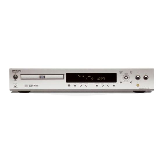
DV-L5
Silver and Titanium color models
MDD
120V AC, 60Hz
MUP, MUT,
100 - 240V, 50/60Hz
MUS, MUR
DV-L5
Ref. No. 3695
082001
ON
OPEN/CLOSE
ON
OPEN/CLOSE
TV
ON/STANDBY
STANDBY
STANDBY
ANGLE
AUDIO
SUBTITLE
ANGLE
AUDIO
SUBTITLE
LAST M
COND. M
DIMMER
DISPLAY
LAST M
COND. M
DIMMER
DISPLAY
TOP MENU
MENU
TOP MENU
MENU
CH -
CH +
VOL +
ENTER
ENTER
VOL -
RETURN
SETUP
RETURN
SETUP
TV/ VCR
TV/ VCR
PAUSE
STOP
PAUSE
STOP
PLAY
PLAY
FR
FF
DOWN
UP
FR
FF
DOWN
UP
STEP/SLOW
STEP/SLOW
+
+
1
2
3
1
2
3
4
5
6
-
4
5
6
-
FUNCTION M
FUNCTION M
7
8
9
7
8
9
SEARCH
CLEAR
SEARCH
CLEAR
+10
0
+10
0
RANDOM REPEAT
A-B
PROGRAM
RANDOM REPEAT
A-B
PROGRAM
REMOTE CONTROLLER RC- 449 DV
REMOTE CONTROLLER RC- 450 DV
DVD
TV
RC-449DV
RC-450DV
<MDD>
<MUP,MUT,
MUS,MUR>
Advertisement
Table of Contents

Related Manuals for Onkyo DV-L5


Summary of Contents for Onkyo DV-L5
-
Page 1: Dvd Player
DV-L5 Ref. No. 3695 082001 DVD Player DV-L5 OPEN/CLOSE OPEN/CLOSE ON/STANDBY STANDBY STANDBY ANGLE AUDIO SUBTITLE ANGLE AUDIO SUBTITLE LAST M COND. M DIMMER DISPLAY LAST M COND. M DIMMER DISPLAY TOP MENU MENU TOP MENU MENU CH - CH +... -
Page 2: Service Note
DV-L5 SERVICE NOTE PRECAUTIONS 1.Ground for the work-desk. Place a conductive sheet such as a sheet of copper (with impedance lower than 10Mohm) on the work-desk and place the set on the conductive sheet so that the chassis. 2.Grounding for the test equipments and tools. -
Page 3: Service Notes
DV-L5 SERVICE NOTES 1. Remove the solder of Laser Diode shorting Connect Pickup and DVD main circuit PC board by FFC(3 pcs). Fix it with the DVD Mecha Remove the solder of Laser Diode shorting on Pickup. Connect total unit of DVD Mechanism (DVD Main PCB + Mechanism) to output terminal. -
Page 4: Specifications
DV-L5 SPECIFICATIONS DVD Player Power supply USA and Canadian models: AC 120 V, 60 Hz Other models: AC 100 -240 V , 50/60 Hz Power consumption USA and Canadian models: 13 W Other models: 12 W Weight 3.7 kg, 8.2 lbs. -
Page 5: Panel View
POWER switch Press to start or resume playback. Turns on the main power supply for the DV-L5. The DV-L5 enters button standby state. Pressing the switch again to the off position ( OFF) shuts down the main power supply into the DV-L5. -
Page 6: Rear Panel
AC OUTLET connector. produce a higher quality picture on your TV or monitor by This means that if the DV-L5 is plugged into an AC outlet, AC connecting to the component video outputs on this unit. power is available to this AC OUTLET even if the DV-L5 is off. - Page 7 AC OUTLET connector. monitor via the S-Video jack. This means that if the DV-L5 is plugged into an AC outlet, AC You can switch between [S1] and [S2] S-video output from the power is available to this AC OUTLET even if the DV-L5 is off.
- Page 8 DV-L5 PANEL VIEW REMOTE CONTROLLER (The illustration shows the RC-449DV remote controller.) FR/FF buttons During playback of DVD and Video CD, press to perform fast OPEN / CLOSE forward scanning or to perform fast reverse scanning of DVD ON / STANDBY...
- Page 9 DV-L5 EXPLODED VIEW P904 P904 P904 <MUP> only E704 <MUP> only <MUP> only E701 P982A <MUR>only F902 <MUT,MUR, F901 MUS> only E702 E903 E904 S731 E901A E703...
-
Page 10: Exploded View Parts List
DV-L5 EXPLODED VIEW PARTS LIST REF. NO. REF. NO. PART NO. PART NO. DESCRIPTION DESCRIPTION 27100406 Chassis E701 2045161512 Flexible flat cable, NCFC5-161512 27191145 Holder (DVD) E702 2045171512 Flexible flat cable, NCFC5-171512 838130088 Self tapping screw, 3TTB+8B E704 2046200512 Flexible flat cable, NCFC6-200512... - Page 11 DV-L5 EXPLODED VIEW PARTS LIST REF. NO. PART NO. DESCRIPTION 1H475500-1E SCART connection terminal PC board ass'y, NAVD-7200-1E <MUP> 1H475501-1A Outlet terminal PC board ass'y, NAPS-7201-1A <MDD> 1H475501-1B Outlet terminal PC board ass'y, NAPS-7201-1B <MUT> <MDD> : North American area (Regional restriction code- 1)
- Page 12 DV-L5 EXPLODED VIEW (LOADING MECHANISM) Daifree GEM1036 To DVDM CN151 Lubricating Oil GYA1001 Lubricating Oil GYA1001 LOADING MECHANISM ASSY PARTS LIST DESCRIPTION REF.NO. PART NO. DESCRIPTION REF.NO PART NO. VNL1918 Float base DVD VNP1836 Loading PC board assy VNL1919 Drive cam...
- Page 13 DV-L5 PRINTED CIRCUIT BOARD CONNECTION DIAGRAM RC-232C connecting U12:digital out terminal PC board PC board NAETC-7382 P251A U5: Outlet terminal PC board U4: SCART connection NAPS-7201 terminal PC board P356B P992C AC-G <MPP> only <MJJ> only P991B NAVD-7200 NAVD-7204 <MJJ> only...
- Page 14 DV-L5 S C H E M A T I C D I A G R A M - 1 U1: Output terminal PC board J L 6 0 1 B N A A R - 7 1 9 7 C 3 6 1...
- Page 15 S C H E M A T I C D I A G R A M - 1 U1: Output terminal PC board N A A R - 7 1 9 7 C 3 6 1 L 3 5 1 B K 1 6 0 8 L M 1 8 2 - T 0 2 0 P 7 0 1 A...
- Page 16 DV-L5 J L 6 0 1 B G N D S W + 5 V C O A X I A L _ O U T G N D P 3 5 3 Q 2 0 4 Q 2 0 5...
- Page 17 DV-L5 S C H E M A T I C D I A G R A M ( 2 ) U 3 : S t a n d b y L E D P C b o a r d...
- Page 18 S C H E M A T I C D I A G R A M ( 2 ) U 2 : D i s p l a y c i r c u i t P C b o a r d N A D I S - 7 1 9 8 Q 7 0 7 Q 7 0 8...
- Page 19 DV-L5 U 3 : S t a n d b y L E D P C b o a r d N A D I S - 7 1 9 8 R 7 4 7 R 7 4 8 R 7 4 9...
- Page 20 DV-L5 DV-L5 SCHEMATIC DIAGRAM (3) U 4 : S C A R T c o n n e c t i o n t e r m i n a l P C b o a r d < M U P > o n l y <...
- Page 21 DV-L SCHEMATIC DIAGRAM (3) U 4 : S C A R T c o n n e c t i o n t e r m i n a l P C b o a r d < M U P > o n l y V + 1 2 V Q 2 5 9 Q 2 5 6...
- Page 22 DV-L5 V-L5 < M J J > O n l y D 1 V i d e o c o n n e c t o r N A V D - 7 2 0 4 N A V D - 7 2 0 0...
- Page 23 DV-L5 SCHEMATIC DIAGRAM (Page 1) Main circuit PC board (RF) : RF SIGNAL ROUTE : RF (VIDEO) SIGNAL ROUTE Page 2 TC7SZU04F IC304 : RF (AUDIO) SIGNAL ROUTE (AD) : AUDIO DATA SIGNAL ROUTE Page 3 : FOCUS SERVO LOOP LINE 3.3k...
- Page 24 DV-L5 SCHEMATIC DIAGRAM (Page 2) VYW1853 CLOCK GENERATOR Page 1 R489 470k : AUDIO (DIGITAL) SIGNAL ROUTE CN401 CN512 MECHA Page1 page 1 IC201 : The power supply is shown with the marked box. To CN15 Page 4...
- Page 25 DV-L5 SCHEMATIC DIAGRAM (Page 3) PAL model only IC806 : RF (VIDEO) SIGNAL ROUTE (VD) : VIDEO DATA SIGNAL ROUTE (AD) : AUDIO DATASIGNAL ROUTE : AUDIO SIGNAL ROUTE : AUDIO (DIGITAL) SIGNAL ROUTE DCS2 from AV1 88p IC801 (VD)
- Page 26 DV-L5 SCHEMATIC DIAGRAM (Page 3) To SCRUT 7,21, 68, 188P IC712 4M MSM51V17805D-60TS (SOP) (VD) Page 1 IC201 Page 1 R334 Page 2/ IC601 to Page 1 Page 3 IC 801 Page 2 IC 601 Page 1 IC 201...
- Page 27 DV-L5 SCHEMATIC DIAGRAM (Page 4) (VD) : VIDEO DATASIGNAL ROUTE : V SIGNAL ROUTE : Y SIGNAL ROUTE : C SIGNAL ROUTE : R SIGNAL ROUTE : G SIGNAL ROUTE : B SIGNAL ROUTE : AUDIO SIGNAL ROUTE page 2...
-
Page 28: Schematic Diagrams
SCHEMATIC DIAGRAMS (Page 1) Main circuit PC board Page 2 Page 3 Page 2 (RF) Page 2 CN151 (RF) CN52 For Mecha connector... - Page 29 DV-L5 (RF) : RF SIGNAL ROUTE : RF (VIDEO) SIGNAL ROUTE TC7SZU04F IC304 : RF (AUDIO) SIGNAL ROUTE (AD) : AUDIO DATA SIGNAL ROUTE ge 3 : FOCUS SERVO LOOP LINE : TRACKING SERVO LOOP LINE 3.3k : SLIDER SERVO LOOP LINE...
- Page 30 SCHEMATIC DIAGRAMS (Page 2) VYW1853 470k CN512 MECHA Page1 page 1 IC201 To CN15 Page 4...
- Page 31 DV-L5 CLOCK GENERATOR Page 1 R489 : AUDIO (DIGITAL) SIGNAL ROUTE CN401 : The power supply is shown with the marked box.
- Page 32 SCHEMATIC DIAGRAMS (Page 4) (VD) (VD) Page 2...
- Page 33 DV-L5 (VD) : VIDEO DATASIGNAL ROUTE : V SIGNAL ROUTE : Y SIGNAL ROUTE : C SIGNAL ROUTE : R SIGNAL ROUTE : G SIGNAL ROUTE : B SIGNAL ROUTE : AUDIO SIGNAL ROUTE page 2 FR CPU page 3...
-
Page 34: Printed Circuit Board Parts List
DV-L5 PRINTED CIRCUIT BOARD PARTS LIST Output terminal PC board (NAAR-7197-1A/1B/1C/1E/1F) CIRCUIT NO. PART NO. DESCRIPTION CIRCUIT NO. PART NO. DESCRIPTION Plugs P711 25055704 NPLG-8P660 Q201 22241623R2 MM1540BF P981 25055675 NPLG-2P631 Q301 22241617R2 DB-VCP301 Holders (PCM-1742KE) P351C,P351D 27190540-1 Capacitors Q351... - Page 35 DV-L5 PRINTED CIRCUIT BOARD PARTS LIST CIRCUIT NO. PART NO. DESCRIPTION CIRCUIT NO. PART NO. DESCRIPTION Diodes Diodes D701 223234R2 or 1SS352 or D251,D252 223266R2 1SS226 D701 or 223269R2 1SS355, Chip Coils D702 224550560R2 UDZS5.6B, Zener L251-L254 230958R1 BK1608LM182-T,Filter D703...
-
Page 36: Packing View
DV-L5 PACKING VIEW P10,P16,P17, P18,P19 RC-449DV <MDD> RC-450DV <MUP/MUT/MUS/ MUR> <MUT,MUS, MUR> P34 <MUP> Front side... -
Page 37: Packing Parts List
DV-L5 PACKING PARTS LIST REF. NO. PART NO. DESCRIPTION REF. NO. PART NO. DESCRIPTION 29091997A Pad ass'y (L/R) 25055911 Conversion plug, CV-K-2 29100141A Poly bag, 700 x 600 <MUT,MUS,MUR> 29110098 Tape, W50 3M NO 371 29053785A Carton box <MDD> 29100201... -
Page 38: Upgrade Firmware
1-2-3 Then the power and standby switches are turn on. 1-1-4 Run the data writing program. EX) Save the program above in C:DV-L5 folder. The program name are B1BK1048.SZ0, Down.bat, down, ok_down.exe, ok_down Open the DOS window "cd DV-L5" and then push the ENTER key. - Page 39 DV-L5 UPGRADE FIRMWARE PAUSE STOP 2. Setting the Region code. PLAY DOWN 2-1 Turn on the power switch and standby switch is turned on. STEP/SLOW 2-2 Select a regional code. (Using the remote controller RC-449DV Part number 24140449) * MDD1N and MJJ2N are automatically chosen. (Automatically witting)
- Page 40 DV-L5 MICROPROCESSOE TERMINAL DESCRIPTION MPD780232GC-041-8BT Pin No. Symbol Function Description Pin No. Symbol Function Description Vdd1 Vdd1 Power supply, +5V P45/FIP37 SMP192LED Sampling rate 192 LED control pin Vss1 Vss1 Ground pin P44/FIP36 SMP96LED Sampling rate 96 LED control pin...
- Page 41 Sales & Product Planning Div. : 2-1, Nisshin-cho, Neyagawa-shi, OSAKA 572-8540, JAPAN Tel: 072-831-8111 Fax: 072-833-5222 ONKYO U.S.A. CORPORATION 18 Park Way, Upper Saddle River, N.J. 07458, U.S.A. Tel: 201-785-2600 Fax: 201-785-2650 E-mail: onkyo@onkyousa.com ONKYO EUROPE ELECTRONICS GmbH Industriestrasse 20, 82110 Germering, GERMANY Tel: 089-849-320 Fax: 089-849-3265 E-mail: info@onkyo.de...
Need help?
Do you have a question about the DV-L5 and is the answer not in the manual?
Questions and answers