Table of Contents
Advertisement
Quick Links
AC to DC
CONVERTER/CHARGER
PM models 15,35,45,55,60,75,85 and
100 Amp 4 Stage Charging
Installation & Maintenance
AC to DC Converter/Charger
SAFETY ALERT
FOR YOUR SAFETY, READ ALL INSTRUCTIONS BEFORE INSTALLATION AND OPERATION.
INSTALLER: Provide these instructions to the end user or consumer.
CONSUMER: Keep these instructions for future reference.
NOTICE: Products are not to be used nor are warranted in aerospace, medical or life safety applications.
Advertisement
Table of Contents

Related Manuals for PowerMax PM15


Summary of Contents for PowerMax PM15
- Page 1 AC to DC CONVERTER/CHARGER PM models 15,35,45,55,60,75,85 and 100 Amp 4 Stage Charging Installation & Maintenance AC to DC Converter/Charger SAFETY ALERT FOR YOUR SAFETY, READ ALL INSTRUCTIONS BEFORE INSTALLATION AND OPERATION. INSTALLER: Provide these instructions to the end user or consumer. CONSUMER: Keep these instructions for future reference. NOTICE: Products are not to be used nor are warranted in aerospace, medical or life safety applications.
- Page 2 WARNING – Avoid Possible Injury or Death 120 VAC is present. This Converter/Charger is designed to convert 120 VAC to 12 VDC. It also provides low voltage power for charging onboard 12 VDC batteries. The Converter/Charger is a “switch mode” type and is designed to be maintenancefree with no user serviceable components. The Converter/Charger power output is “current limiting” by design. WARNING – Avoid Personal Injury or Product Damage NEVER store electrical devices in compartments where flammable liquids (such as gasoline) exist. DO NOT mount/install unit in compartments designed for storage of batteries of flammable liquids. DISCONNECT DC POWER. Disconnect the battery POS (+) wire at the battery end before connecting this Converter/Charger to any vehicle/device wiring. LOCATION. The mounting location may be on any interior (out of direct weather) surface. Location chosen must be accessible after installation. When mounted inside a cabinet, the cabinet must be large enough to allow dissipation of heated air. Make sure that there is a minimum of 1” (one inch) free air space at each end of the unit so that cooling air can move through the unit properly. AVOID foreign contaminants such as dirt, metal particles or moisture. MOUNTING. Flanges with holes are provided for ease of mounting using standard fasteners. Confirm that the surface that the converter is mounted to is solid and will hold the weight (6 lbs) during vehicle operation. ELECTRICAL REQUIREMENTS. A 120 VAC receptacle needs to be located within 36 inches of the Converter/Charger to supply power. Electrical consideration should also be given to mounting near the locations of the batteries and the 12volt DC distribution panel. ELECTRICAL CONNECTIONS. Be sure to tighten all connections securely. A loose connection can quickly cause terminals and wires to overheat. Review unit labels for recommended terminal torque values. WARNING – Avoid Possible Injury or Death 120 VAC Connection – First confirm that the 120 VAC power source AC circuit breaker(s) are in the off position. DO NOT turnon AC circuit breakers until installation is complete. ● Using an 8 AWG minimum size copper wire, attach from the vehicle/device chassis to the Converter/Charger Bonding Lug. ● Using the attached power cord on the Converter/Charger, connect firmly to the 120 VAC receptacle 12 VDC Wiring– It is important to use the correct wire gauge. Use a minimum of 8 AWG size copper wire. ● The terminal marked + or POS is for the RV 12 VDC positive connection. ● The terminal marked – or NEG is for the RV 12 VDC negative connection. ● The 12 VDC output wiring does not require overcurrent protection because the Converter/ Charger limits current output. However, all electrical connections need to comply with the appropriate NEC code.
- Page 3 4 S C O D . This system provides an automatic charging system in four steps. 1. A fast charge to TAGE HARGING PTION ESCRIPTION bring a good, drained battery back up to full voltage rapidly ("Boost"). 2. A standard charge to bring the battery up to a full charge at a safe rate to prolong the life of the battery and provide power to run 12V lighting and appliances in the vehicle/device ("Normal"). 3. A trickle charge to keep the battery fresh during times of load inactivity ("Storage"). 4. A higher Boost mode is cycled through every 22 hours in a 24 hour continuous cycle to help with battery maintenance and improved charging. (“Desulfation”). The charger automatically changes modes to accommodate changes in conditions. TEST. First, disconnect all loads and battery on the Converter/Charger by removing all 12 VDC connections from + or POS . Second, attach a multimeter instrument between the positive and negative terminals of the Converter/Charger. Then energize the 120 VAC converter circuit. Test for proper output power using the multimeter. Measure the output voltage from the positive and negative terminals. The voltage should read 14.6 +/ 0.2 VDC. Add 12 VDC load connections to about 2/3 of the rated capacity of the converter. Recheck the voltage, which should remain approximately the same as at no load. BATTERY. With the 120 VAC disconnected, reconnect the + or POS positive terminal to a known good battery. With the converter 120 VAC energized, measure the voltage at the converter and at the battery. The voltage should be about the same in both locations. As with any battery it is important that the fluid level be checked on a regular basis. When continuously connected to any charging source all batteries will “Gas” and lose some fluid. WARNING – Avoid Personal Injury / Product Damage HIPOT TESTING. (Vehicle/device Manufacturing Facilities Only) DO NOT HiPot DC wiring with the Converter/Charger connected to the vehicle/device wiring in order to prevent serious injury and/or damage.
- Page 4 TROUBLESHOOTING NOTE: Before removing and replacing the Converter/charger, perform the following checks: Disconnect the AC power from the vehicle/device. Disconnect the wiring and Battery from the Converter Positive + output terminal. Reconnect the AC power to energize the Converter. Using a voltmeter, measure the voltage at the Converter – and + Output terminals. > The Converter is OK if the voltage reading is between 13 VDC and 14 VDC (typically 13.6 VDC). > Otherwise check the table below: CONDITION POSSIBLE CAUSE ● No 12 VDC output 120 VAC not connected to coach or the coach AC circuit breaker is in the off position. ● Reversed battery fuses blown. (Battery wiring connections are reversed), ● Severe overload or shorted load. Remove all loads and retest per above instructions. ● Converter/Charger internal failure. ● Converter cycles On & Off Fan air flow is inadequate or blocked. (1” minimum free air space at each end required) ● Converter/Charger internal failure. ● Reversed Battery fuses blown Battery wiring connections are reversed. ● Defective battery, possible bad cells. ● 12 VDC output is too low Attached load exceeds rating of the Converter/Charger. ● Defective battery, possible bad cells. ● Converter/Charger internal failure.
- Page 6 TWO YEAR LIMITED WARRANTY Limited Warranty and Remedy: PowerMax. (“Supplier”) warrants products it sells against faulty workmanship or the use of defective materials and that such products will conform to published specifications, drawings and ...
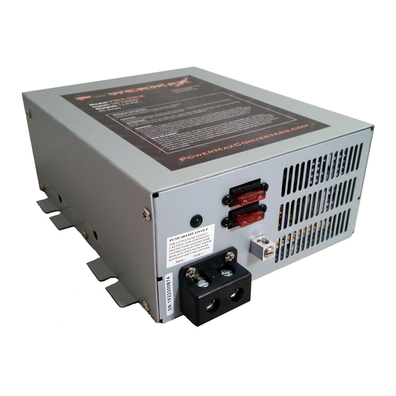
- Page 7 ‘ReversedBattery’ Fuses Chassis Bonding Lug 12 VDC Output Terminals AIR FLOW FAN (on backside) . . . . Blows air out of front grill vents.
Need help?
Do you have a question about the PM15 and is the answer not in the manual?
Questions and answers