
Related Manuals for Gamewell IdentiFlex 610


Summary of Contents for Gamewell IdentiFlex 610
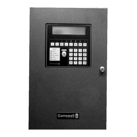
- Page 1 IdentiFlex 610 ANALOG / ADDRESSABLE FIRE ALARM CONTROL PANEL INSTALLATION & OPERATION MANUAL GAMEWELL P/N 71810 12 CLINTONVILLE ROAD ISSUE E, 9/10/2004 NORTHFORD, CT 06472 FIRMWARE VER. 7.2 ECN 04-488...
- Page 2 While a fire alarm system may lower insurance Fire Alarm System Limitations rates, it is not a substitute for fire insurance! An automatic fire alarm system–typically made up of smoke Heat detectors do not sense particles of combustion and alarm detectors, heat detectors, manual pull stations, audible warn- only when heat on their sensors increases at a predetermined ing devices, and a fire alarm control with remote notification...
-
Page 3: Installation Precautions
Installation Precautions Adherence to the following will aid in problem-free installation with long-term reliability: WARNING - Several different sources of power can be con- Like all solid state electronic devices, this system may nected to the fire alarm control panel. Disconnect all sources operate erratically or can be damaged when subjected to light- of power before servicing. -
Page 4: Table Of Contents
Table of Contents SYSTEM DESCRIPTION ..............1 GENERAL ............................3 ..........................3 EATURES XP95-M Analog Addressable Multisensor Detector..............3 Programmable Sounder Bases....................3 Multi Protocol UDACT........................3 ............................4 ELEASING .........................6 YSTEM VERVIEW IF 610 Control Panel ........................6 ....................6 YSTEM ODULAR ONSTRUCTION Common Control Section......................6 System I/O Components......................7 SYSTEM OPERATION ...............9 ........................11 PERATOR... - Page 5 Addressable Input Devices ......................33 Wiring Guides ..........................34 .........................35 NITIAL YSTEM TARTUP SYSTEM TEST MODE..............37 Overview ............................39 Walk Test ...........................39 ByPass Mode..........................41 ByPass Group Programming .....................44 Input Test ...........................45 Output Test ..........................46 Display ............................47 Configure...........................47 Dict.............................48 Events ............................48 Misc............................48 Pass ............................49 Codes............................49 Tally ............................49 Ver .............................49...
- Page 6 Restore ............................72 Alarm Levels ..........................72 Available ............................72 Special ............................73 Signal Circuit Functions ......................73 Restoring Outputs ........................73 Initializing an analog Circuit .......................74 .........................74 ONTROL VENT CBE Programming ........................75 To select "logical" Group Inputs....................75 To assign a "logical" Output Group....................76 ........................77 UNCTION ROGRAMMING ........................78 YSTEM...
- Page 7 Upload Dictionary........................100 Dictionary File ..........................101 Change Card..........................102 Test Menu ..........................103 Test Input IF 610........................103 Test Output IF 610 ........................103 Test ID ............................103 Test Gnd ............................104 Test Lamps ..........................104 Test Analog..........................105 OVERVIEW ................107 OMPUTER APTOP ROGRAMMING Overview of Computer Programming ..................107 Interconnect ..........................107 Communication Protocol......................107 ASCII Transfer ..........................110...
- Page 8 This Page intentionally blank...
-
Page 9: System Description
Section IF 610 System Description... - Page 10 This Page intentionally blank...
-
Page 11: General
GENERAL IdentiFlex 610 Fire Alarm Control Panel with firmware, version r7.2 is an update of the prior versions of IF 610 FACP firmware. The version r7 provides all of the features and performance of the previous IF 610 firmware as well as many... -
Page 12: Releasing
There are special functions which can be accomplished with the Gamewell Series 610 Fire Alarm Control Panel. One is Releasing, which allows control of dump or deluge forms of fire suppression. RELEASING The Gamewell Series 610 Fire Alarm Control Panel, with version r7 firmware, and Analog Addressable devices, can provide all of the required functions to control the releasing of bulk fire suppressant materials. - Page 13 Programming WARNING! In order to properly prepare the inputs and outputs required for Releasing, very specific programming steps must be performed. Failure to follow these steps could result in failure of the suppressant to be discharged, or there could be unplanned discharge of the suppressant. The following describes the steps to be taken to program the IF 610 FACP for releasing.
-
Page 14: System Overview
SYSTEM OVERVIEW IF 610 The Gamewell. IF 610 is a microprocessor based fire alarm control panel. The IF Control Panel 610 system is available in three configurations; a 126 point, one circuit analog/addressable circuit control panel (IF 610-126), a 252 point, two circuit analog/addressable circuit control panel (IF 610-252), and a 504 point, four circuit analog/addressable circuit control panel (IF 610-504). -
Page 15: System I/O Components
System I/O Components The analog addressable module is a 1, 2, or 4 circuit card that monitors and controls Analog Addressable up to 126 analog/addressable devices (points) per circuit for a total of 504 points per Module module. The analog interface module has its own microprocessor which simultaneously communicates with the connected field devices and with the main CPU. - Page 16 This Page intentionally blank...
-
Page 17: System Operation
Section IF 610 System Operation... - Page 18 This Page intentionally blank...
-
Page 19: Operator Controls
Common Control Display-Functional Description OPERATOR CONTROLS >>NOTE: THE “ENABLE” KEY SWITCH MUST BE ACTIVATED BEFORE ANY OF THE PUSH BUTTON SWITCHES WILL OPERATE The “Acknowledge” switch (ACK) silences the internal buzzer of the panel and returns to normal any signal circuit or relay programmed to return to normal condition, when the "ACK"... -
Page 20: Indicators
SIGNAL The “Signal Silence” switch (SIGNAL SILENCE) will silence (i.e. return to normal), any circuit or relay that is programmed to restore on Signal Silence. SILENCE The Signal Silence switch is an alternating action switch. Pressing the Signal Silence switch will return the silenced circuits to an active state. DRILL The “Drill”... -
Page 21: System Operating Conditions
BYPASS The “Bypass” LED indicates that points which have been programmed for bypass are actually bypassed. WALK The “Walk test” LED indicates that the panel is in the walk test mode. TEST SYSTEM OPERATING CONDITIONS When shipped from the factory, the IF 610 system has been initialized to a Default Mode minimal "default"... -
Page 22: Alarm Condition (Default)
Status :Normal MM/DD/YY HH:MM System Idle Figure O-1 The IF 610 will go into an ALARM state when any analog/addressable initiation Alarm Condition (default) device reports an alarm condition. By default the following actions will occur at the common control display. Refer to Table O-1, System Events Messages in the Appendix for complete listing of message displays. -
Page 23: Operating Procedures
Display for Multiple Alarm(s) • NOTE: Multiple alarms are shown after the words ALARM Total “x”; with “x” representing the total amount of alarms. Status : ALARM Total X MM/DD/YY HH:MM Fire Alarm in Ckt#_ Dev#:_ Figure O-3 OPERATING PROCEDURES Acknowledging When the user presses the "ACK"... - Page 24 In the Alarm condition, the red LED for SIGNAL SILENCE will begin to flash. Signal Silence This guided prompt feature notifies the user that it is possible, but not necessary, to press the SIGNAL SILENCE switch. In the default mode, all signal circuits will silence.
-
Page 25: Alarm Verification
Alarm Verification Alarm verification is used to reduce the occurrence of nuisance alarm conditions (transient smoke etc.). Careful consideration should be taken before enabling the Alarm Verification feature on any device. Programming the Alarm Verification feature may delay the reporting of an actual emergency. Only those devices that are subject to conditions that require verification should be programmed with this feature. -
Page 26: Releasing
Releasing A group of initiating and output devices can be designated to control the release of fire suppression agents. The process includes the ability to intercede in (Abort) the cycle, or speed up (Dump) the cycle. The delay time from the confirmation of two anded inputs to the release command is programmable, as is the delay from the release command to the actual release. -
Page 27: Trouble Condition
Trouble Condition A trouble condition occurs when a fault or potential problem develops within the system, system components, or system wiring connections. When a fault is detected the system common Trouble Display LED will be illuminated on the common control display, and the system common audible will be sounded. - Page 28 THIS PAGE INTENTIONALLY BLANK...
-
Page 29: Installation
Section IF 610 Installation... - Page 30 THIS PAGE INTENTIONALLY BLANK...
-
Page 31: If 610 System Housing
The IF 610 system is a compact stand-alone unit. The 12.5”H x 18.5”W x 4.5”D System cabinet houses the CPU module, Operators Display, the Bus Driver Module, the Housing Analog Addressable Interface Modules, and the power supply. A 6"H x 5"W x 4"D area is reserved for batteries. - Page 32 System Assembly (Refer to drawing C-M818-2 Assembly of IF 610 Cabinet) 1. Dress all wires away from the inside of the cabinet. Ensure the cabinet is clean before mounting the assemblies. Clean as required. 2. Mount the Bus Driver Card PN 31025 3.
-
Page 33: Module Identification And Placement
Module Identification and Placement Modular The IF 610 system utilizes a unique addressing scheme that allows it to supervise Functions card placement and monitor card types. This addressing scheme monitors specific pre-assigned module locations in the IF 610 system. The module locations used in the IF 610 system are locations 0, 4, 5, 6 and 17. -
Page 34: Specifications
Refer to D-W1175, Wiring, IF 610 System; and drawing C-M818-2 Assembly of Installation IF 610 Cabinet for installation and cable connections. Diagram Specifications Input Voltage 120 VAC 50/60 Hz 3 amps Max. 220/240 VAC 50/60 Hz. 2 Amps Max. Power Fail / Brownout Transfer Per UL 864 Operating Temperature 0 to +49 degrees C... -
Page 35: Cpu Module
Power Requirements • 2mA operating current • 1mA for each Red LED (ON) • 6mA for each Yellow or Green LED (ON) CPU Module The CPU module (or microprocessor module) contains the system operating firmware and non-volatile memory. It provides all the system memory and processing functions as well as providing the local/remote communications and supervision. -
Page 36: Bus Driver Module
Cable Connections: SBX1 connector Interconnection (ribbon cable) to J3 connection on the bus driver module SBX0 connector Interconnection (ribbon cable) to SmartNet adapter. P1 connector Laptop interface - use ribbon cable 71332 P2 connector Normally not used. Jumper JP5 should be placed between pins 2 and 3 P4 (pins 3 &... -
Page 37: Common Control Specifications
Cable Connections J3 Connector Interconnect (ribbon cable) to SBX1 on the CPU module J2 Connector Interconnect (ribbon cable) to P1 on the Analog Addressable module J1 Connector Interconnect (ribbon cable) to J3 on the operators display COMMON CONTROL SPECIFICATIONS Common Control The specifications listed identify the interfacing modules housed in the common control section;... - Page 38 Signal Circuit 1** Signal CCT#1, 24V@2A, Style Y or Z Style Y requires 3.9K ohm end of the line resistor. 1L1R Style Z (-) Return (-) Signal Power (+) Signal Power 1L2R Style Z (+) Return Signal Circuit 2** Signal CCT#2, 24V@2A, Style Y or Z Style Y requires 3.9K ohm end of the line resistor.
-
Page 39: Analog Interface Module & Subassembly Specifications
RELAY 4 Designation Description SPARE 4 NO Form C normally open spare contact 4 NC Form C normally closed spare contact Form C spare relay common contact 2.0A @ 30 VDC or 120 VAC @ 1.0 amps. ISO 232 Designation Description RS-232 Out Term. -
Page 40: Analog Circuit Wiring Requirements And Limitations
Circuit 2 Terminal # Designation Description +24V Device power TB-2 +24 R +24V Device power Style 6 return Addressable line (-) Style 6 addressable (-) return Addressable line (+) Style 6 addressable (+) return Circuit 3 Terminal # Designation Description TB-3 +24V Device power +24 R... -
Page 41: Addressable Input Devices
Addressable Input Gamewell’s IF 610 series of Addressable Input Devices provide the interface between the IF 610 Analog circuits and contact devices. The input devices are Devices available as a point identification device (PID-95) and as an addressable manual station (MS-95). Point Identification devices provide for a style B circuit. PID-95(P) The PID-95 is intended to provide the interface between contact devices and the Installation... -
Page 42: Wiring Guides
Wiring Guides WIRING GUIDELINES SIGNALING CIRCUIT WIRE SIZES 24 VOLT DC PARALLEL WIRE PAIR IN DISTANCE TO LAST DEVICE RESISTANCE (MAXIMUM LINE LOSS 10%) OHM/1 0.5amp 1.0amp 1.5amp 2.0amp 400' 200' 130' 100' 620' 300' 210' 160' 1000' 500' 330' 250' 1600' 800'... -
Page 43: Initial System Startup
INITIAL SYSTEM STARTUP CAUTION ! Connect primary power to the system before connecting battery/standby power source. 1. Activate main power. The "Power ON" message (Figure I-1) is displayed. Power ON / Hardware Reset Please Wait ... Figure I-1 2. Wait the required 15 seconds. [Power ON] LED is flashing. Commencing System Reset screen is displayed (see Figure I-2). - Page 44 This Page intentionally blank...
-
Page 45: System Test Mode
Section IF 610 System Test Mode... - Page 46 This page intentionally blank...
-
Page 47: Overview
Walk Test, Bypass mode, Detector/Device Test, and information displays can be Overview selected at any time from the Password Protected - Access Level 3. Function Programming Menu by pressing one of the FN keys on the left or right arrow keys, and selecting the desired test as indicated on the LCD screen. - Page 48 Walk Test Prog Menu 1=Inputs 2=Inputs/Sig 3=Devices 4=Clear 0=Exit 1=Inputs Places all inputs in Walk Test 2=Inputs/Sig Places all Inputs and Signal Circuits in Walk Test 3=Devices Allows individual selection of Inputs and Signal circuits to place in Walk Test through the following procedures.
-
Page 49: Bypass Mode
>>NOTE: Signal Circuits 1 and 2 located on the Operators Display are Numbers 129 and 130, respectively. 10. The display will show the status of the signal circuit in respect to Walk Test. Use the up/down arrow keys to toggle the signal circuit into and out of the Walk Test mode. When you have made your selection, press the “Enter”... - Page 50 Function Programming 1=Walk Test 2=Bypass 3=Input Test 4=Output Test 5=Display 0=exit >2 BYPASS MENU 1=DISPLAY 2=PROG 0=EXIT Figure T7 ∆ WARNING ! Devices will not report an alarm or trouble condition. A Fire Watch or other reliable means should be employed to monitor the unprotected area.
- Page 51 6. Use the up/down arrow keys to select the circuit of the devices to be bypassed. >>NOTE: Use the right arrow key to place the cursor under the device address. 7. Use the up/down arrow keys to select the device address. When the device address is selected, the device type, zone type and zone status will be displayed automatically.
-
Page 52: Bypass Group Programming
ByPass Group Programming 1. Select [4] from the ByPass Menu. Figure T11 is now displayed ByPass Group Programming 1=Assign Devices to ByPass Group 2=Activate/Deactivate ByPass Groups 0=Exit Figure T11 2. Select [1] from the menu to assign Devices to ByPass groups, then select either [1} for Inputs, or [2] for Outputs 3. -
Page 53: Input Test
Input Test The Input test function allows the user to individually test the functionality of each device, operation and response. Device LED will illuminate if selected for Input Test. The LED will turn off when the device is deselected. Function Programming 1=Walk Test 2=Bypass 3=Input Test 4=Output Test 5=Display 0=exit >3... -
Page 54: Output Test
T-1 DEVICE TEST TABLE Input Device Display Description Trouble / Background Dirty Pre-Alarm Alarm / Shorted/ Panel on 1st Active Feedback Ionization 0 - 9 10 - 40 41 - 44 Background Background Detector Opt. Photo Detector 0 - 9 20 - 30 41 - 44 25 +... -
Page 55: Display
The Display Function allows the Operator to view or download the system Display configuration, dictionaries, operating information, and current detector values. Function Programming 1=Walk Test 2=Bypass 3=Input Test 4=Output Test 5=Display 0=exit >5 Display 1=Config 2=Dict. 3=Events 4=Misc. 5=Detectors 0=Exit Display 1=Config 2=Dict. -
Page 56: Dict
The Dictionary Menu allows selection of either viewing or downloading the Dict. system dictionaries. Display 1=Config 2=Dict. 3=Events 4=Misc 5=Detectors 0=Exit >2 Display Dictionary Menu 1=Display 2=Download 3=Exit Display 1=Config 2=Dict. 3=Events 4=Misc 5=Detectors 0=Exit >3 The Events Menu allows viewing of the system events log Events Use up/down keys to scroll Press Enter key to Exit... -
Page 57: Pass
The Passwords Menu Is not available in this mode. It requires a Level 4 password Pass to activate. This Function Is Only Accessible At Security Level 4 Display Menu (Misc.) 1=Pass 2=Codes 3=Tally 4=Ver 5=Ram 0=exit >2 Codes The Codes Menu allows viewing of the programmed Codes Use up/down keys to scroll Press Enter key to Exit Tally... -
Page 58: Memory
Display Menu (Misc.) 1=Pass 2=Codes 3=Tally 4=Ver 5=Ram 0=exit >5 Memory The Memory Display shows the available Random Access Memory. Unallocated Bytes of Ram: 206123 Press Any Key To Continue Display 1=Config 2=Dict. 3=Events 4=Misc 5=Detectors 0=exit >4 Detectors The Display Detectors menu allows the downloading of the smoke and heat detector sensitivity values. -
Page 59: Programming
Section IF 610 Programming... - Page 60 THIS PAGE INTENTIONALLY BLANK...
- Page 61 PROGRAMMING OVERVIEW 1 Circuit programming 1 Inputs 2 Outputs 3 Init 2 Control by Event 3 Function programming 1 Walk test 1 Display 2 Program I Inputs 2 Inputs/Sig. 3 Devices 4 Clear 2 Bypass 1 Display 2 Program 1 Device 2 I/0 Groups 3 Circuits 4 Bypass groups...
- Page 62 4 System 1 Display 1 Configuration 1 Display 2 Download 2 Dictionary 1 Display 2 Download 3 Events 4 Misc. 1 Display pass codes 2 Display codes 3 Tally 4 Display software version 5 Display available RAM 5 Detectors 1 Download 2 Change 1 Menu 1 1 Pass Codes...
- Page 63 3 Test 1 Inputs 2 Outputs 3 Card I.D 4 Ground fault 5 Lamp test 6 Analog test...
-
Page 64: Introduction
INTRODUCTION The SmartStart automated programming process feature is available in the "SmartStart" Gamewell’s IF 610 control panels. This initialization process uniquely configures the system parameters in memory. The system automatically ties its inputs to its outputs through the creation of the Control-By-Event tables. During power-up and after a hardware reset, the controller decides if the system has previously had a configuration in memory. - Page 65 Programming Prompts (continued) Throughout the programming sequence, the user is prompted to enter data selections at the location of the flashing cursor. To select sub- menu options, use the following prompts: To Select a Field Option Use Right and Left arrow keys to horizontally scroll and select option field.
-
Page 66: System Startup
SYSTEM STARTUP This section is subdivided into two sections, Initial System Startup and System Restart / Re- Configuration. Instructions for a newly installed system, or a system in which the firmware has been changed, are detailed in the Initial System Startup section. Instructions for a "hardware reset" are detailed in the System Restart / Re-Configuration section. -
Page 67: System Restart / Re-Configuration - Smartstart
SYSTEM RESTART / RE-CONFIGURATION - SMARTSTART ∆ WARNING ! All programming data will be lost when the system is re- configured. The system will initialize the SmartStart feature and will configure a new data base. Hardware Reset 1. Complete a hardware reset by shorting the jumper pins on P4, located on the CPU card. Figure 2 screen will be displayed. -
Page 68: System Idle Display
Hardware Reset (continued) 5. After a 15 second delay, the system commences a hardware restart. Modules and devices are being read and will scroll up on the display, Figure 3C. Next the System RESET screen is shown, Figure 2A. Then the "System Idle" screen is displayed, Figure 4. Polling Card XXX Circuit XXX Address XXX Polling Card XXX Circuit XXX Address XXX Polling Card XXX Circuit XXX Address XXX... -
Page 69: Password Entry
The four access level default settings are: Access level 1 = Ack. Access level 2 = Ack., Sig. Sil., Reset, Drill Access level 3 = Ack., Sig. Sil., Reset, Drill, Det. test, Walk Test, Bypass Access level 4 = Programming, SmartStart Default passwords for the access levels are: Password 1111 = Access level 1 Password 2222 = Access level 2... -
Page 70: Programming Mode
PROGRAMMING MODE Main Display The main programming display shows the user an overview of the programming modes. The user is allowed to select from four categories. (Figure 6) Programming Mode 1=Ckt. Prog. 2=CBE 3=Function 4=System 0=Exit > Figure 6 1= Ckt Prog Circuit Programming 2 = CBE Control-By-Event... -
Page 71: Inputs" Circuit Selection
"Inputs" Circuit Selection 1. From the Circuit Programming menu, Press [1] on keypad. 2. Press "Enter". >>NOTE: The cursor will be flashing under the circuit number. If the device type is an ion detector Figure 8 will be displayed. Ckt:XX Add:XXX D_Type: Ion Z_Type: XXXX I_GRP:XXX Figure 8 >>NOTE: The display starts with Circuit 1 and begins with the... -
Page 72: Device Selection
Device Selection 4. Use the left/right arrow keys to move the cursor flashing under the device address "Add:xxx", enter the address number or use the up/down arrow keys to select the address of the device to be modified then press enter. Photo Device Sensitivity Selection ∆... -
Page 73: Heat Device Operating Selection
Heat Device Operating Selection 4.3 To select a heat detector operating characteristic or use the left/right arrow keys to scroll to "R/R". Use the up arrow key to select "Y" (Yes) rate of rise function. When rate of rise is selected the device will alarm when it detects a 15°... - Page 74 >>NOTE: It is not necessary to press "Enter" when the Up/Down arrow keys are used to change the parameter of a field. The field contents are automatically updated for the device as shown on the display (Except I_Grp). 10. When all input devices have been programmed, press "Enter" to exit the input circuit programming mode.
- Page 75 ZONE TYPE TABLE - P2 Display Panel Name Description Verification Automatically verifies the device). (Default program, after a 45 sec. Min., 60 sec. Max Reset/Stabilization delay, monitors the device for 60 seconds to verify an alarm condition. Auto Automatic Places the panel into General Alarm AutSB Automatic detector Places the panel into General Alarm.
-
Page 76: Output Circuit Programming
TEXT DICTIONARY TABLE - P4 Fire Alarm Smoke Detector 1st. Floor Room Number Alarm Heat Detector 2nd. Floor Corridor Duct Detector 3rd. Floor Elevator Lobby Sprinkler Water flow 4th. Floor Trouble Tamper switch 5th. Acknowledge Manual Station 6th. Floor-Closet Pull Station 7th. - Page 77 Ckt:xxx D_Type:xxx Alr: XX Sig:xxxx Res:xxx Drl:x Sil:x Figure 11 3.2 When an analog addressable line is selected for programming from the operators display, Figure 11B. The yellow LED of the selected circuit will illuminate Ckt:xxx Add:xxx D_Type:xxx Alr: XX O_Grp:xxx Res:xxx Seq:x...
-
Page 78: Field Descriptions For Signal Circuits And Analog Addressable
Field Descriptions for Signal Circuits and Analog Addressable “Ckt:xxx” Indicates the signal circuits memory address “Add:xxx Address of analog relay module “D_Type:Sig” Shows the type of output circuit “ALR:x” Indicates to what alarm level the circuit will be activated in the event that “and”... -
Page 79: Signal Circuit Types
Signal Circuit Types Output Signal Circuit Type A. STEADY DC Steady DC type signal circuit is the System Default. When Activated, any signal circuits programmed for Steady DC will provide a 24VDC uninterrupted output. B. MARCHTIME 60 Marchtime 60 circuits, when activated, will provide a 24 VDC output on the selected circuits at a 60 pulses per minute rate with a duration of 50% on and 50% off cycle. -
Page 80: Signal Circuit
Signal Circuit Restore A. Restore On - ACKNOWLEDGE For use with supplementary signaling and functions Any active output point programmed to restore on ACKNOWLEDGE will return to Idle whenever the Acknowledge switch is pressed. All output points that were returned to Idle will reactivate upon a subsequent alarm which is programmed to activate those output points. -
Page 81: Special
Special Signal Circuit Functions A. SIGNAL SILENCE INHIBIT Silence Inhibit will prevent the operation of the Signal Silence function for a programmable period ranging from 30 seconds to 5 minutes from the time the first point goes into alarm. If the panel is programmed for Silence Inhibit any activation of the Signal Silence Switch will be ignored, allowing the output signal circuits to be active, until the programmed delay has elapsed. -
Page 82: Initializing An Analog Circuit
Initializes an individual circuit. Allows the user to add new devices (detectors) Initializing an or remove devices in the specific circuit selected. All other circuit information analog Circuit previously entered (utilized in Control By Event data base programming) is protected and cannot be altered or damaged. 1. -
Page 83: Cbe Programming
CBE Programming Control-by-Event "CBE" programming is dedicated to system wide ALARM functions. Select "CBE" (#2) from the main "Programming Mode" menu to change or assign input group assignment with the associated output group. To select "logical" Group Inputs 1. Select "CBE" (2) from the main "Programming Mode" menu. 2. -
Page 84: To Assign A "Logical" Output Group
To assign a "logical" Output Group 5. Press "Enter". Figure 15 is now displayed. Enter Output Group: XXX Figure 15 6. Using numeric keys, enter the desired output group number or press the signal circuit switch. The assigned output group number now is displayed in top left as shown in Figure 15A. -
Page 85: Function Programming
FUNCTION PROGRAMMING See System Test Mode... -
Page 86: System Programming
SYSTEM PROGRAMMING Programming System programming menus may be accessed if the proper programming password is entered at the “ENTER PASSWORD:” prompt. Programming may also be performed from a laptop computer connected to the RS-232 port on the CPU of the control panel. Refer to the end of this section for instructions. >>NOTE: Before proceeding, notify all personnel, monitoring companies and municipalities the system will be temporarily... -
Page 87: Display Config
Display Config. The system module configuration is displayed when option 1 is selected from the Configuration Menu. This display shows the modules that are present in each card location, their associated card type, code and a description of the card. The modules displayed are retrieved from the system configuration memory and are not a real time scan of the actual cards present (refer to the system test menu for a real time display). - Page 88 Card ID # Each type of card is assigned a unique 8 bit code that the card transmits to the CPU when it is polled. In operation each card is periodically polled and returns its type code. The CPU detects if the card is functioning correctly, for a card type at that location.
-
Page 89: Download Config
Download Selecting Download from the Display Configuration Menu will prompt the system to transmit the complete system configuration file to the RS-232 port. When this is selected Config the system prompts the user to perform several steps. These steps are the actions required to receive an ASCII file when using PROCOMM communications software. -
Page 90: Display Dict. Menu
This display option allows the user to view the contents of word dictionaries 1 - 5. Display Dict. Dictionaries 1 - 4 may contain up to 128 entries and dictionary 5 may contain up to 1024 Menu entries. By selecting this option the contents of all 5 user dictionaries are output to the laptop/computer screen. -
Page 91: Display Events
Display Events The display events selection will prompt the CPU to output it’s complete history log to the RS-232 port. The history log will contain all information regarding the system status changes for the previous 1000 events or since the last time the system SmartStart™ feature was invoked. -
Page 92: Display Codes
Displaying the codes will allow the user to view the codes that are assigned to each of the Display Codes 256 input groups. This is followed by information on the timing of the codes, number of rounds transmitted and whether the system reverts to March Time coding or silences after the coding is completed. -
Page 93: Tally
This displays the number of times that a detector which is selected for Verification, has Tally activated without confirmation within the last 30 days. Display Menu (Misc.) 1=Pass 2=Codes 3=Tally 4=Ver 5=Ram 0=Exit >3 Press any Key To Continue Display Ver. The version of firmware installed in the main CPU will be displayed when 3 (Ver) is selected from the Display Menu (Misc.). -
Page 94: Change Menu 1
The system change menu allows the user to change various system parameters. Change Menu Change Menu 1 Change Menu 1=Menu 1 2=Menu 2 3=Menu 3 4=Menu 4 0=Exit > Change Menu 1=Menu 1 2=Menu 2 3=Menu 3 4=Menu 4 0=Exit >1 Change Menu 1 1=Pass 2=Code 3=Date 4=Seq... -
Page 95: Change Pass
The Change Password menu is used to change the password, user name and/or the access Change Pass level associated with the passwords. When this is selected from Change Menu 1, the previously programmed password information is displayed, followed by a prompt requesting the password number to be changed. -
Page 96: Change Code
The codes in the IF 610 systems are assigned to the input groups. When a device within Change Code that group alarms, that code would be sounded on the signal circuits that have been programmed as coded circuits. Each input group may be assigned an individual code that contains up to 6 digits. -
Page 97: Change Date
To change the date and/or time in the IF 610 system, the Change Date Menu must be Change Date selected. This menu prompts the user with the information the system requires to enter a new time and date. Change Menu 1 1=Pass 2=Code 3=Date 4=Seq 5=Baud 0=Exit >3... -
Page 98: Change Seq
The Change Sequence option allows the user to redefine the access levels associated with Change Seq each of the sequence keys. Each of these keys is assigned an access level by default. The Acknowledge key is assigned to level 1 access. The Reset, Signal Silence and Drill keys are assigned to level 2. - Page 99 SW1 - Settings Open Do Not Change Open Do Not Change Always Closed Do Not Change Open Do Not Change Open Do Not Change Open Do Not Change Note: P2 baud rate of is selected via S7 and S8. Auto Detect Baud rate is utilized for peripheral devices.
-
Page 100: Change City
Change Menu 2 Change Menu 1=Menu 1 2=Menu 2 3=Menu 3 4=Menu 4 0=Exit >2 Change Menu 2 1=City 2=Ann 3=Trbl 4=BCKey 5=Day Enable 6=Day/Night 0=Exit Change City The City Tie Circuit is designed to operate in four modes of operation; Line Reversal, Master Box, Dialer, and Chicago mode. -
Page 101: Change Trbl
The Change Trouble option should be in the “Troubles are Annunciated” Mode. This Change Trbl feature is used in Special Applications where a backup system is required. Special modules and wiring are required to utilize this option. Please consult your factory representative for applications requiring redundant system operation. -
Page 102: Change Day Night Mode
The Change Day Night option allows the selection of manual or automatic termination of Change Day Positive Alarm Sequence. Night Mode Change Menu 2 1=City 2=Ann 3=Trbl 4=BCKey 5=Day Enable 6=Day/Night 0=Exit >6 System In Manual Day Mode Press Enter Key To Exit Press Any Other Key To Toggle >1 System Is In Auto Day Mode... -
Page 103: Change Prefix
This option allows the user to change the Prefix for alarm events that occur. The default Change Prefix setting is FIRE Alarm. If the panel were monitoring Gas detectors, for example. The Prefix could be changed to GAS and therefore display GAS Alarm during alarm conditions. Change Menu 3 1=Abort 2=Prefix 3=Config 4=Tally 5=Sil Inh 6=AutoSil 0=Exit... -
Page 104: Change Silence Inhibit Delay
The Change Sil Inh option allows the selection of the time period in which Silence is Change Silence inhibited after an alarm signal. Inhibit Delay Change Menu 3 1=Abort 2=Prefix 3=Config 4=Tally 5=Sil Inh 6=AutoSil 0=Exit >5 Sil Inh Delay Is Set To: 0 Min Enter New Signal Sil Delay (0-10) Delay=Entry (0-10) X 30 sec Change... -
Page 105: Change Config
Change Menu 4 Change Menu 1=Menu 1 2=Menu 2 3=Menu 3 4=Menu 4 0=Exit >4 Change Menu 4 1=Cfg 2=Water 3=Relse 4=Dump 5=Dict 6=Card 0=Exit Change Config. Changing the system configuration requires a previously downloaded system configuration file. This option is only available when programming through a P. C. attached to the serial port, or from the Master in a network. -
Page 106: Change Discharge Delay
The Change Dump option allows the selection of the time delay from the Discharge Change command to the actual Discharge.. Discharge Delay Change Menu 4 1=Cfg 2=Water 3=Relse 4=Dump 5=Dict 6=Card 0=Exit >4 Discharge Delay Is Set To: 0 sec Enter Discharge Delay (0-30 sec): Change Changing the dictionary entries can be achieved by two means, changing the words or... - Page 107 To select word options from the control panel: Prompt Description <a1> = first lower case letter of a word or key <a2> = second lower case letter of a word or key <a3> = third lower case letter of a word or key <a#>...
-
Page 108: Upload Dictionary
>>NOTE: When changes are made to any dictionaries they are appended to the existing dictionary. Therefore the entire number of added text may change when you exit the programming area. For example, if dictionary 2 has twelve entries and you add an entry as number 15, when enter the word the dictionary is appended and your new entry becomes number 13. -
Page 109: Dictionary File
The dictionary file format consists of the five dictionaries, each separated by two fore Dictionary File slashes (//) as delimiters. The first line of the dictionary file would contain two fore slashes indicating that it is the beginning of the file and the next line received will be word #0 of dictionary #1. -
Page 110: Change Card
Change Card IMPORTANT: THE ONLY CARD THAT CAN BE CHANGED IN THE IF 610 IS CARD #17 IN ORDER TO CHANGE THE NUMBER OF CIRCUITS. IF 610 system allow components to be added or deleted without disturbing the programming (Control By Event, etc.) of other system components. When the Change Card menu is selected, an Add or Delete option is then prompted. -
Page 111: Test Menu
The test menu is a useful tool when testing and troubleshooting the IF 610 systems. The Test Menu various options allow the testing of input and output devices, circuits, ground fault monitoring and system communications. Test Menu 1=Input 2=Output 3=ID 4=Gnd 5=Lamp 6=Analog 0=Exit The Input Test does not function on IF 610 since there are no conventional inputs. -
Page 112: Test Gnd
Test Menu 1=Input 2=Output 3=ID 4=Gnd 5=Lamp 6=Analog 0=Exit >3 00=0C 01=FF 02=FF 03=FF 04=01 05=02 06=05 07=FF 08=FF 09=FF 10=FF 11=FF 12=FF 13=FF 14=FF 15=FF 16=FF 17=09 18=FF 19=FF 20=FF 21=FF 22=FF 23=FF 24=FF 25=FF 26=FF 27=FF 28=FF 29=FF 30=FF 31=FF 32=FF 33=FF 34=FF 35=FF 36=FF 37=FF 38=FF 39=FF 00=0C 01=FF 02=FF 03=FF 04=01 05=02... -
Page 113: Test Analog
Test Analog The analog test is designed to allow the user to control and obtain “real time” information about individual analog addressable devices. When analog is selected from the Test Menu ,the system prompts the user to enter the channel of the card and device address. The “Data to Send”... - Page 114 Display Description Trouble / Background Dirty Pre-Alarm Alarm / Shorted/ Panel on 1st Active Feedback Ionization 0 - 9 10 - 40 41 - 44 Background Background Detector Opt. Photo Detector 0 - 9 20 - 30 41 - 44 25 + 25 + (non-comp.)
-
Page 115: Computer/Laptop Programming Overview
COMPUTER/LAPTOP PROGRAMMING OVERVIEW Overview This section describes the system communications via a computer. System monitoring, Computer general control functions and system programming can be achieved from a computer Programming terminal. All figures shown are displayed on the computer screen. The 14 pin ribbon cable P/N 71332, is used to connect the computer to the CPU Module Interconnect port P2. - Page 116 Select Direct Com 1 (or 2), click on OK Select Baud rate, (usually 2400)select Data bits = 8, select Parity = N, select Stop bits = 1, and Flow control = Xon / Xoff. Click on OK...
- Page 117 5. Select the pull down File menu at the top of the screen. Select Properties, Select the Settings tab, and set Emulation to VT-100 Select ASCII Setup, change Line delay setting to 1 millisecond, change Char delay setting to 1 millisecond, Click on OK.
-
Page 118: Ascii Transfer
ASCII Transfer From the ASCII TRANSFER SETUP menu select option 6 to display the ASCII TRANSFER SETUP menu. The following settings should be displayed. ASCII UPLOAD 1) Echo locally ..NO 2) Expand Blank Lines ... NO 3) Pace character ..0 (ASCII) 4) Character pacing .. -
Page 119: Appendix
Section 5 IF 610 Appendix... -
Page 120: Flex 600 Compatible Indicating Appliances
FLEX 600 COMPATIBLE INDICATING APPLIANCES PART MODEL NUMBER DESCRIPTION CURRENT NUMBER 70874 MB-G6-24-R MOTORBELL 6" .030 70875 MB-G10-24-R MOTORBELL 10" .030 71557 RSP-2430-VFR 30 Cd Strobe Adapter Red .124 71631 SRP-2475-VFR 75 Cd Strobe Adapter Red, Sync. .215 71558 RSP-2475-VFR 75 Cd Strobe Adapter Red .200 71561... - Page 121 FLEX 600 COMPATIBLE INDICATING APPLIANCES (Cont.) 71294 MT-24-MS-VFR Multi-tone Horn/Strobe Red 30 Cd See DS851 PART MODEL NUMBER DESCRIPTION CURRENT NUMBER 71140 MT-24-WM-VFR Multi-tone Horn/Strobe Red 110 Cd See DS851 71426 MT-24-SL-VFR Multi-tone Horn/Strobe Red 15 Cd Sync See DS851 71427 MT-24-SLM-VFR Multi-tone Horn/Strobe Red 15/75 Cd Sync...
- Page 122 WIRING GUIDELINES SIGNALING CIRCUIT WIRE SIZES 24 VOLT DC PARALLEL WIRE PAIR IN DISTANCE TO LAST DEVICE RESISTANCE (MAXIMUM LINE LOSS 10%) OHM/1 0.5amp 1.0amp 1.5amp 2.0amp 400' 200' 130' 100' 620' 300' 210' 160' 1000' 500' 330' 250' 1600' 800' 520' 400'...
- Page 123 PART# / IDENTIFIER DESCRIPTION COMPATIBLE BASES / MOUNTING QTY MAX XP95-P Photo-Electric Analog XP95-B4, XP95-B6, XP95-B6LOW, Smoke Sensor XP95-B6R4, XP95-B6SNDR XP95-I Ionization Analog Smoke XP95-B4, XP95-B6, XP95-B6LOW, Sensor XP95-B6R4, XP95-B6SNDR XP95-T Thermal Analog Sensor XP95-B4, XP95-B6, XP95-B6LOW, XP95-B6R4, XP95-B6SNDR XP95-PD Photo-Electric Duct Provided Analog Smoke Sensor...
-
Page 124: Identiflex 610 Battery Calculation Chart
IdentiFlex 610 BATTERY CALCULATION CHART NORMAL ALARM MODULE NORMAL CURRENT ALARM CURRENT TOTAL TOTAL MAIN .171 +signal Ckt. Current +.002 for master box or .022 for reverse polarity S+S- NOTE A+A- NOTE 1 LOOP .030 .050 ANALOG IO 2 LOOP .035... -
Page 125: Drawings
Section 6 IF 610 Drawings... - Page 126 This Page intentionally blank...
- Page 127 Drawings C-M818-2 Assembly of IF 610 Vertical Cabinet A-W572 Wiring RSI-95 used for Releasing Service A-W548 Wiring IF 610 Connections to Com4 Communicator D-W1175 Wiring IF 610 System C-M818-6 Assembly of IF610 in a surface/flush cabinet.
-
Page 139: Limited Warranty
Limited Warranty The manufacturer warrants its products to be free from defects in materials and workmanship for eighteen (18) months from the date of manufacture, under normal use and service. Products are date-stamped at time of manufacture. The sole and exclusive obligation of the manufacturer is to repair or replace, at its option, free of charge for parts and labor, any part which is defective in materials or workmanship under normal use and service. - Page 140 12 Clintonville Rd., Northford, CT 06472-1653 P/N 71810 Rev E 9/10/04...
Need help?
Do you have a question about the IdentiFlex 610 and is the answer not in the manual?
Questions and answers