Table of Contents
Advertisement
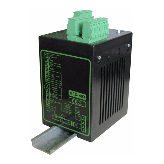
RESISTRON
RES-403
Operating
Instructions
Important features
•
Microprocessor technology
•
Automatic zero calibration (AUTOCAL)
•
Automatic optimization (AUTOTUNE)
•
Automatic configuration of the secondary voltage and current ranges
(AUTORANGE, as of October 2005)
•
Automatic phase angle compensation (AUTOCOMP, as of October 2005)
•
Automatic frequency adjustment
•
Large current and voltage range
•
Set point selection with potentiometer
•
0...10VDC analog output for ACTUAL temperature
•
Activated with contact or 24VDC signal
•
Alarm function with fault diagnosis
•
Heatsealing band alloy and temperature range selectable
Industrie-Elektronik GmbH
Gansäcker 21
D-74321-Bietigheim-Bissingen (Germany)
GB
Tel: +49/(0)7142/7776-0
Fax: +49/(0)7142/7776-19
E-Mail:
info@ropex.de
Internet:
www.ropex.de
Data subject to change
Advertisement
Chapters
Table of Contents

Related Manuals for Toss ROPEX RESISTRON RES-403


Summary of Contents for Toss ROPEX RESISTRON RES-403
- Page 1 RESISTRON RES-403 Operating Instructions Important features • Microprocessor technology • Automatic zero calibration (AUTOCAL) • Automatic optimization (AUTOTUNE) • Automatic configuration of the secondary voltage and current ranges (AUTORANGE, as of October 2005) • Automatic phase angle compensation (AUTOCOMP, as of October 2005) •...
-
Page 2: Table Of Contents
Contents Safety and warning notes ....3 Controller functions ....23 Use . -
Page 3: Safety And Warning Notes
Safety and warning notes Safety and warning notes This RESISTRON temperature controller The RESISTRON temperature controller must be set manufactured according to DIN EN 61010-1. In the and coded according to the temperature coefficient of course of its manufacture it passed through quality the heatsealing band. -
Page 4: Line Filter
Application Standards / CE marking operating safety. They are not included in the scope of supply of the standard control system and are described in a separate document. The controller described here complies with the following standards, provisions and directives: Line filter DIN EN 61010-1 Safety provisions for electrical... -
Page 5: Principle Of Operation
Principle of operation The use of RESISTRON temperature controllers • Increased machine capacity results in: • Extended life of the heatsealing bands and teflon coatings • Repeatable quality of the heatseals under any con- ditions • Simple operation and control of the sealing process Principle of operation The resistance of the heatsealing band, which is tem- to the required dynamic range despite the exceptionally... -
Page 6: Description Of The Controller
Description of the controller Description of the controller The microprocessor technology endows the RESIS- The ACTUAL temperature of the heatsealing band is TRON temperature controller RES-403 with previously supplied to an analog 0…10VDC output. The real heat- unattainable capabilities: sealing band temperature can thus be displayed on an external temperature indicator (e.g. -
Page 7: Modifications (Mods)
Accessories and modifications Line filter Essential in order to ensure CE conformity. Optimized for the RESISTRON temperature controller. Impulse transformer Designed according to VDE 0570/EN 61558 with a one section bobbin. Optimized for impulse operation with RESISTRON temperature controllers. Specified according to the heatsealing application ( ROPEX Application Report). - Page 8 Accessories and modifications MOD 40 If the actual temperature leaves the tolerance band, the output signal is deactivated again. The output signal Additional terminal for "Temperature reached" signal. then remains deactivated, even if the actual tempera- This output signal is activated when the ACTUAL ture subsequently returns to the tolerance band.
-
Page 9: Technical Data
Technical data Technical data Type of construction Housing for installation in the electrical cabinet Snaps onto a standard top hat rail (DIN TS35 rail, 35 mm) acc. to DIN EN 50022 Dimensions: 90 x 75mm; height: 135mm (incl. terminals) Line voltage All controllers manufactured as of October 2005: 115VAC version: 110VAC -15%…120VAC +10% (equivalent to 94…132VAC) 230VAC version: 220VAC -15%…240VAC +10% (equivalent to 187…264VAC) - Page 10 Technical data Alarm relay = 50VDC, I = 0.2A, potential-free Maximum load = 5A (duty cycle = 100%) (primary current of = 25A (duty cycle = 20%) impulse transformer) Power dissipation max. 20W Ambient +5…+45°C temperature Degree of protection IP20 Installation If several controllers are installed on one top hat rail (DIN TS35 rail), a clearance of at least 20mm...
-
Page 11: Dimensions
Dimensions Dimensions 75.0 90.0 Installation See also section 1 "Safety and warning notes" on controller in the range from 47Hz…63Hz. page 3. 3. Install the RESISTRON temperature controller in the electrical cabinet on a standard top hat rail (DIN Installation and startup may only be per- TS35 rail, according to DIN EN 50022). -
Page 12: Installation Steps
Installation Installation steps Use heatseal bands with suitable temperature coefficient Heatseal element push-on with coppered ends connectors Heatsealing band R= f (T) No additional Connect U measuring resistance wires directly to in secondary Note heatsealing band ends circuit number Sufficient wire of turns Twisted cross-section... -
Page 13: Power Supply
Installation Power supply LINE Line L1 (L1) 115VAC, 230VAC, 400VAC N (L2) GND/ Earth Circuit breaker Double-pole, C characteristic ROPEX Application Report) Short-circuit protection only. > > RESISTRON temperature controller not protected. Relay Ka "HEAT ON - OFF" function (all-pole) "EMERGENCY STOP". -
Page 14: Line Filter
Installation Line filter installed and wired correctly, they guarantee com- pliance with the EMC limit values. You can find the exact specification of the line filter in To comply with EMC directives – corresponding to the ROPEX Application Report calculated for your par- EN 50081-1 and EN 50082-2 –... -
Page 15: Wiring Diagram (Standard)
Installation Wiring diagram (Standard) Line filter LF-xx480 NOTE: RES-403 AUTOCAL button LINE also provided on (also with MOD 01) controller AUTOCAL with 24VDC signal ALARM OUTPUT max. 50V/0,2A Contact closed or opened by ALARM (see configuration) START (HEAT) with 24VDC signal prim. -
Page 16: Wiring Diagram With Booster Connection (Mod 26)
Installation Wiring diagram with booster connection (MOD 26) Line filter LF-xx480 NOTE: RES-403 AUTOCAL button LINE also provided on (also with MOD 01) controller Booster AUTOCAL with 24VDC signal ALARM OUTPUT max. 50V/0,2A Contact closed or opened by ALARM (see configuration) START (HEAT) with 24VDC signal prim. -
Page 17: Wiring Diagram With "Temp- Erature Reached" Signal (Mod 40) Or „Temp. Ok" Signal (Mod 46)
Installation MOD 26 cannot be used in combination with MOD 40 ("Temperature OK" signal) manufactured up to September 2005. ALARM HEAT OUTPUT AUTOCAL BOOSTER Additional terminals in housing cover for MOD 26 (Booster connection) Wiring diagram with "Temp- erature reached" signal (MOD 40) or „Temp. -
Page 18: Startup And Operation
Installation Startup and operation 8.10 View of the controller LEDs Terminals Button for AUTOCAL function Wiring diagramm Nameplate Coding switches and plug-in jumpers 8.11 Controller configuration range from 30A to 500A. If the voltage and/or the current is outside the permissible range, a detailed error message appears on the controller ( The controller must be switched off in order section 9.12 "Error messages"... - Page 19 Installation Factory settings DIP switch DIP switch 1...10V 30...100A 6...60V 60...200A 20...120V 120...400A If the secondary current I is less than 30A, the PEX-W2 or PEX-W3 current transformer must have two turns ( ROPEX Application Report). 8.11.2 Configuration of the rotary coding switch for the temperature range and alloy Switch...
-
Page 20: Replacing And "Burning In" The Heatsealing Band
Installation 8.11.3 Configuration of the alarm relay Alarm relay contact DE-ENERGIZED / PC CONFIGURATION opened by alarm/ AT ALARM ALARM OUTPUT ENERGIZED PC-CONFIGURATION. Alarm relay contact closed by alarm. (factory setting) If the plug-jumper is not inserted - or if it is rature coefficient TCR. -
Page 21: Startup Procedure
Installation 8.12.2 Replacing the heatsealing band powered up correctly. All power supply leads must be disconnected from the As of SW-Revision 106: RESISTRON temperature controller in order to replace If the red "ALARM" LED lights up for 0.3s in the heatsealing band. addition to the yellow "AUTOCAL"... - Page 22 Installation 8.13.2 Restart after replacing the heat- actual value output: The controller is functioning correctly if the tempera- sealing band ture (which corresponds to the signal change at the To replace the heatsealing band, proceed as described analog output) has a harmonious motion, in other in section 8.12 "Replacing and "burning in"...
-
Page 23: Controller Functions
Controller functions Controller functions See also section 8.6 "Wiring diagram (Standard)" on page 15. Indicators and controls Manufactured as of October 2005 Red LED, lights up or blinks to indicate ALARM. ALARM Yellow LED, lit during heating phase. HEAT OUTPUT AUTOCAL Green LED, indicates pulses in measure- ment mode. -
Page 24: Temperature Setting (Set Point Selection)
Controller functions In addition to the functions shown in the diagram by the LEDs. These states are described in detail in the above, various controller operating states are indicated table below: Blinks slowly (1Hz) Blinks fast (4Hz) Lit continuously RESET active, AUTOCAL START and AUTOCAL AUTOCAL requested, but... -
Page 25: Temperature Indication
Controller functions Temperature indication (actual The relationship between the change in the output voltage and the ACTUAL temperature is linear. value output) 0 - 300°C range °C The RES-403 supplies an analog 0…10VDC signal, which is proportional to the real ACTUAL temperature, at terminals 14+15. -
Page 26: Automatic Zero Calibration (Autocal)
Controller functions This indicator moreover permits disturbances in the control loop (loose connections, contacting or wiring 24VDC problems) as well as any line disturbances to be RES- 403 observed extremely effectively and interpreted accor- AUTOCAL dingly. The same applies if mutual interference occurs max. -
Page 27: Start" Signal (Heat)
Controller functions You should always wait for the heatsealing • By means of a 24VDC signal at terminals 12+13 band and the bar to cool down (to ambient 24VDC temperature) before activating the AUTOCAL RES- 403 START function. (HEAT) max. 6mA Reasons for disabled AUTOCAL function: 1. -
Page 28: Measuring Impulse Duration (As Of October 2005)
Controller functions The alarm output is switched if the "START" signal is If the interval between the two "AUTOCAL" functions is activated while an alarm signal is indicating error codes longer than 2.0s, "AUTOCAL" is executed normally 104…106, 111…114, 211, 302 or 303 (up to Sep- again the second time. -
Page 29: Temperature Diagnosis (As Of October 2005)
Controller functions Temperature diagnosis tolerance band limit is exceeded, the temperature dia- gnosis is not activated until the parameterized delay (as of October 2005) time has elapsed. The temperature diagnosis function can thus be explicitly deactivated, e.g. if the tempera- An additional temperature diagnosis can be activated in ture drops temporarily owing to the closure of the the ROPEX visualization software (... -
Page 30: Diagnostic Interface/Visualization Software
Controller functions 9.10 Diagnostic interface/visualization 2. Blinks slowly (1Hz) The system configuration is incorrect and the zero software (as of October 2005) calibration (AUTOCAL function) was unsuccessful section 8.11 "Controller configuration" An interface with a 6-pole Western socket is provided page 18). -
Page 31: Error Messages
Controller functions An alarm can only be reset by switching the and causes" on page 36 permits each fault to be controller off and then on again. cleared quickly and efficiently. 13 voltage levels for fault diagnostics appear at the Invalid alarm signals may appear when the actual value output of all controllers manufactured as of controller is switched off owing to the unde-... - Page 32 Controller functions Page 32 RES-403...
- Page 33 Controller functions RES-403 Page 33...
- Page 34 Controller functions Page 34 RES-403...
- Page 35 Controller functions RES-403 Page 35...
-
Page 36: Fault Areas And Causes
Controller functions 9.13 Fault areas and causes Temperature controller HARDWARE The table below explains the possible fault causes. Fault area Explanation Possible causes Load circuit interrupted after U - Wire break, heatsealing band break - Contact to heatsealing band defective pickoff point PEX-W2/-W3 current transformer measuring wires from current transformer interrupted... -
Page 37: Factory Settings
Factory settings Fault area Explanation Possible causes - Up to September 2005: DIP switches 4 + 5 configured incorrectly (I range) signal incorrect - As of October 2005: I outside permissible range from 30…500A Turns through PEX-W2/-W3 - Check number of turns (two or more turns required for current transformer incorrect currents <... -
Page 38: Maintenance
Maintenance Measuring impuse Measuring impulse length: 1,7ms duration „Temp. OK“ signal Tolerance band: -10K…+10K (as of October 2005: With MOD 46 only) Temperature Temperature diagnosis: OFF diagnosis Heatup timeout Heatup timeout: OFF [X] As of October 2005: With ROPEX visualization software only. Maintenance The controller requires no special maintenance. -
Page 39: How To Order
How to order How to order Contr. RES - 403 / . . . VAC 115: Power supply 115VAC, Art. No. 740301 230: Power supply 230VAC, Art. No. 740302 400: Power supply 400VAC, Art. No. 740303 Scope of supply: Controller includes connector plug-in parts (without current transformer) Modification MOD . - Page 40 How to order Booster B- . . . 400 075: Max. pulse load 75A, 400VAC, Art. No. 885301 100: Max. pulse load 100A, 400VAC, Art. No. 885304 For more accessories: "Accessories" leaflet Page 40 RES-403...
-
Page 41: Index
Index Index Impulse transformer Installation Accessories Installation procedure Actual value output Installation regulations Alarm output Alarm relay Alloy Ambient temperature Line filter Analog temperature meter Line frequency Application Line voltage Application Report AUTOCAL AUTOCOMP Maintenance Automatic phase angle compensation Measuring impulse duration Automatic zero calibration Modifications AUTOTUNE... - Page 42 Index Temperature range Temperature reached signal View of the controller Temperature setting Visualization software Transformer Type of construction Wiring Wiring diagram Page 42 RES-403...
Need help?
Do you have a question about the ROPEX RESISTRON RES-403 and is the answer not in the manual?
Questions and answers