Table of Contents
Advertisement
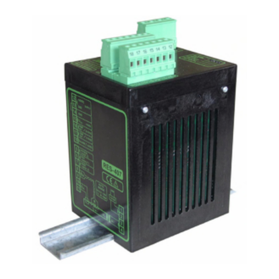
RESISTRON
RES-407
Operating
Instructions
Important features
•
Microprocessor technology
•
Automatic zero calibration (AUTOCAL)
•
Automatic optimization (AUTOTUNE)
•
Automatic configuration of the secondary voltage and current ranges
(AUTORANGE, as of April 2005)
•
Automatic phase angle compensation (AUTOCOMP, as of April 2005)
•
Automatic frequency adjustment
•
Large current and voltage range
•
Electrically isolated analog input for set point selection with potentiometer or 0...10VDC
•
Electrically isolated 0...10VDC analog output for ACTUAL temperature
•
24VDC control signals for START, AUTOCAL and RESET with electrical isolation
•
Alarm function with fault diagnosis
•
Heatsealing band alloy and temperature range selectable as standard (as of June 2003)
GB
Toss Machine Components, Inc.
Toss Machine Components, Inc.
539 S. Main Street, Nazareth. PA 18064
539 S. Main Street, Nazareth. PA 18064
Phone 610-759-8883 Fax 610-759-1766
Phone 610-759-8883 Fax 610-759-1766
E-Mail: info@tossheatseal.com
E-Mail: info@tossheatseal.com
Exclusive Sales and Service:
Exclusive Sales and Service:
www.tossheatseal.com
www.tossheatseal.com
Advertisement
Chapters
Table of Contents

Related Manuals for Toss ROPEX RESISTRON RES-407


Summary of Contents for Toss ROPEX RESISTRON RES-407
- Page 1 Heatsealing band alloy and temperature range selectable as standard (as of June 2003) Exclusive Sales and Service: Exclusive Sales and Service: www.tossheatseal.com www.tossheatseal.com Toss Machine Components, Inc. Toss Machine Components, Inc. 539 S. Main Street, Nazareth. PA 18064 539 S. Main Street, Nazareth. PA 18064 Phone 610-759-8883 Fax 610-759-1766 Phone 610-759-8883 Fax 610-759-1766 E-Mail: info@tossheatseal.com...
-
Page 2: Table Of Contents
Contents Safety and warning notes ....3 Startup and operation ....19 Use . -
Page 3: Safety And Warning Notes
Safety and warning notes Safety and warning notes This RESISTRON temperature controller The RESISTRON temperature controller must be set manufactured according to DIN EN 61010-1. In the and coded according to the temperature coefficient of course of its manufacture it passed through quality the heatsealing band. -
Page 4: Line Filter
Application Standards / CE marking operating safety. They are not included in the scope of supply of the standard control system and are described in a separate document. The controller described here complies with the following standards, provisions and directives: Line filter DIN EN 61010-1 Safety provisions for electrical... -
Page 5: Principle Of Operation
Principle of operation • etc. • Increased machine capacity The use of RESISTRON temperature controllers • Extended life of the heatsealing bands and teflon coatings results in: • Simple operation and control of the sealing process • Repeatable quality of the heatseals under any conditions Principle of operation The resistance of the heatsealing band, which is... -
Page 6: Description Of The Controller
Description of the controller Description of the controller microprocessor technology endows directly on the machine PLC or by means of an external RESISTRON temperature controller RES-407 with potentiometer (PD-x). previously unattainable capabilities: Similarly, the real heatsealing band temperature can be visualized either on the display of the machine PLC or •... -
Page 7: Modifications (Mods)
Accessories and modifications Set point potentiometer PD-x Front panel-mounting version for setting the required SET heatsealing temperature of the RESISTRON temperature controller. The number which appears on the display corresponds to the SET heatsealing temperature in °C. Line filter Essential in order to ensure CE conformity. Optimized for the RESISTRON temperature controller. - Page 8 Accessories and modifications MOD 21 MOD 37 (until May 2003) Inverts the alarm signal (terminal 18). If an alarm is Additional rotary coding switch for the heatsealing band signaled, the alarm output is switched to open condition alloy and the temperature range. Various heatsealing (LOW).
- Page 9 Accessories and modifications MOD 46 (as of April 2005) If the actual temperature leaves the tolerance band, the output signal is deactivated again. The output signal Additional terminal for "Temperature OK" signal. If this then remains deactivated, even if the actual tempera- modification is installed, the RES-407 checks whether ture subsequently returns to the tolerance band.
-
Page 10: Technical Data
Technical data Technical data Type of construction Housing for installation in the electrical cabinet Snaps onto a standard top hat rail (DIN TS35 rail, 35mm) acc. to DIN EN 50022 Dimensions: 90 x 75mm; height: 135mm (incl. terminals) Line voltage All controllers manufactured as of April 2005: 115VAC version: 110VAC -15%…120VAC +10% (equivalent to 94…132VAC) 230VAC version: 220VAC -15%…240VAC +10% (equivalent to 187…264VAC) - Page 11 Technical data Reference voltage +10VDC / ±5%, I = 5mA Digital logic levels LOW (0V): 0…2VDC, electrically isolated Terminals 5, 6, 7 HIGH (24VDC): 12…30VDC (max. current input 6mA) Reverse polarity-protected Switching output for = 30VDC "Temp. OK" signal = 50mA (MOD 40) <...
-
Page 12: Dimensions
Dimensions Dimensions 75.0 90.0 Installation See also section 1 "Safety and warning notes" on automatically detected by the temperature controller page 3. in the range from 47Hz to 63Hz. 3. Install the RESISTRON temperature controller in Installation startup only the electrical cabinet on a standard top hat rail (DIN performed by technically trained, skilled TS35 rail, according to DIN EN 50022). -
Page 13: Installation Steps
Installation Installation steps Use heatseal bands with suitable temperature coefficient Heatseal element push-on with coppered ends connectors Heatsealing band R= f (T) No additional Connect U measuring resistance wires directly to in secondary Note heatsealing band ends circuit number Sufficient wire of turns Twisted cross-section... -
Page 14: Power Supply
Installation Power supply LINE Line L1 (L1) 115VAC, 230VAC, 400VAC N (L2) GND/ 50/60Hz Earth Circuit breaker Double-pole, C characteristic ROPEX Application Report) Short-circuit protection only. > > RESISTRON temperature controller not protected. Relay Ka "HEAT ON - OFF" function (all-pole) "EMERGENCY STOP". -
Page 15: Line Filter
Installation Line filter installed wired correctly, they guarantee compliance with the EMC limit values. You can find the exact specification of the line filter in To comply with EMC directives – corresponding to the ROPEX Application Report calculated for your EN 50081-1 and EN 50082-2 –... -
Page 16: Auxiliary Voltage
Installation Auxiliary voltage maximum current input of 1,0A and it is also protected against reverse polarity. Since the inputs and outputs of the RES-407 are electrically isolated, a 24VDC auxiliary voltage must be Wiring diagram (standard) applied to terminals 12+13. The auxiliary voltage has a Line filter LF-xx480 RES-407 LINE... -
Page 17: Wiring Diagram With Booster Connection (Mod 26)
Installation Wiring diagram with booster connection (MOD 26) Line filter LF-xx480 RES-407 LINE (also with MOD 01) AUTOCAL Booster with 24VDC signal START (HEAT) with 24VDC signal RESET with 24VDC signal prim. Impulse transformer Ground for 24VDC signals. sec. Must be grounded externally to prevent electrostatic Heat-... -
Page 18: Wiring Diagram With "Temp- Erature Reached" Signal (Mod 40) Or „Temp. Ok" Signal (Mod 46)
Installation MOD 26 cannot be used in combination with MOD 40 ("Temperature OK" signal) manufactured up to March 2005. ALARM HEAT OUTPUT AUTOCAL BOOSTER Additional terminals in housing cover for MOD 26 (booster connection) Wiring diagram with "Temp- erature reached" signal (MOD 40) or „Temp. -
Page 19: Startup And Operation
Startup and operation Startup and operation View of the controller Terminals LEDs Wiring diagram Nameplate Coding switches and plug-in jumpers Controller configuration current is outside the permissible range, a detailed error message appears on the controller ( section 10.13 "Error messages" on page 32). The controller must be switched off in order to configure the coding switches and the Configuration with coding switches... - Page 20 Startup and operation Factory settings DIP switch DIP switch 1...10V 30...100A 6...60V 60...200A 20...120V 120...400A If the secondary current I is less than 30 A, the PEX-W2 or PEX-W3 current transformer must have two turns ( ROPEX Application Report). 9.2.2 Configuration of the rotary coding switch for the temperature range and alloy (as of June 2003)
-
Page 21: Heatsealing Band
Startup and operation 9.2.3 Configuration of the alarm output (as of April 2005) Alarm output opened DE-ENERGIZED / PC CONFIGURATION (HIGH) by alarm/ AT ALARM ALARM OUTPUT ENERGIZED PC-CONFIGURATION. Alarm output closed (LOW) by alarm. (factory setting) If the plug-jumper is not inserted - or if it is corrected after a few heating cycles ( section 9.3.2 incorrectly inserted - an error message... -
Page 22: Startup Procedure
Startup and operation Each time the heatsealing band is replaced, the zero As of SW-Revision 106: point must be calibrated with the AUTOCAL function If the red "ALARM" LED lights up for 0.3s in while the band is still cold, in order to compensate addition to the yellow "AUTOCAL"... - Page 23 Startup and operation 9.4.2 Restart after replacing the curve, in other words it must not jump abruptly, fluctuate or deviate temporarily in the wrong heatsealing band direction. This kind of behavior would indicate that To replace the heatsealing band, proceed as described the U measuring wires have been laid incorrectly.
-
Page 24: Controller Functions
Controller functions Controller functions See also section 8.6 "Auxiliary voltage" on page 16. 10.1 Indicators and controls Manufactured as of April 2005 Red LED, lights up or blinks to indicate ALARM. ALARM Yellow LED, lit during heating phase. HEAT OUTPUT AUTOCAL Green LED, indicates pulses in measure- ment mode. -
Page 25: Temperature Setting
Controller functions In addition to the functions shown in the diagram by the LEDs. These states are described in detail in the above, various controller operating states are indicated table below: Blinks slowly (1Hz) Blinks fast (4Hz) Lit continuously RESET active, AUTOCAL requested, but AUTOCAL START and AUTOCAL... -
Page 26: Temperature Indication
Controller functions If a ROPEX PD-x precision potentiometer is used, the 0 - 300°C range °C SET temperature can be adjusted exactly with the help of the digital display in the window of the dial. The number which appears on the display corresponds to the SET temperature in °C. -
Page 27: Automatic Zero Calibration
Controller functions observed extremely effectively interpreted The "AUTOCAL" function is activated by means of a accordingly. The same applies if mutual interference 24VDC pulse at terminals 5+14. occurs between several neighboring control loops. 24VDC RES-407 If an alarm is signaled, this analog output is AUTOCAL used to display a selective error message section 10.13 "Error messages"... -
Page 28: Start" Signal (Heat)
Controller functions 3. If the "START" signal (24VDC) is active, the The set point that is selected for the heatsealing "AUTOCAL" function is not executed ("HEAT" LED temperature must be greater than 40°C. If not, the lit). heatsealing band will not be heated up. The alarm output is switched if the "START"... -
Page 29: Measuring Impulse Duration
Controller functions controller performs internal If the interval between the two "AUTOCAL" initialization lasting approximately functions is longer than 2.0s, "AUTOCAL" is 500ms after the "RESET" signal is deactivated. The executed normally again the second time. next heatsealing process cannot be started until it AUTOCAL has finished. -
Page 30: Temperature Diagnosis
Controller functions ∆ϑ temperature. lower upper AUTOCAL lower ∆ϑ ) tolerance band limits are configured in the signal upper 24VDC factory to -10K and +10K. These values can be set „AC“ independently another ROPEX visualization software. If the actual temperature is inside the specified tolerance band when the "START"... -
Page 31: Heatup Timeout
Controller functions 10.10 Heatup timeout Only a ROPEX comunication interface is allowed to be connected to the diagnostic (as of April 2005) interface. Connecting another device (e.g. a telephone cable) could result in malfunctions or An additional heatup timeout can be activated in the damage to the controller. -
Page 32: Error Messages
Controller functions If the alarm relay is configured opposite to the factory Invalid error messages may appear when the setting ( section 9.2.3 "Configuration of the alarm controller is switched off owing to the output (as of April 2005)" on page 21), these states are undefined operating state. - Page 33 Controller functions RES-407 Page 33...
- Page 34 Controller functions Page 34 RES-407...
- Page 35 Controller functions RES-407 Page 35...
- Page 36 Controller functions Page 36 RES-407...
-
Page 37: Fault Areas And Causes
Controller functions 10.14 Fault areas and causes Temperature controller HARDWARE The table below explains the possible fault causes. Fault area Explanation Possible causes Load circuit interrupted after U - Wire break, heatsealing band break - Contact to heatsealing band defective pickoff point PEX-W2/-W3 current transformer measuring wires from current transformer interrupted... -
Page 38: Factory Settings
Factory settings Fault area Explanation Possible causes - Up to March 2005: DIP switches 4 + 5 configured incorrectly range) signal incorrect - As of April 2005: I outside permissible range from 30…500A Turns through PEX-W2/-W3 - Check number of turns (two or more turns required for current transformer incorrect currents <... -
Page 39: Maintenance
Maintenance Measuring impuse Measuring impulse length: 1,7ms duration „Temp. OK“ signal Tolerance band: -10K…+10K (as of April 2005: With MOD 46 only Temperature Temperature diagnosis: OFF diagnosis Heatup timeout Heatup timeout: OFF [X] As of April 2005: With ROPEX visualization software only. Maintenance The controller requires no special maintenance. -
Page 40: How To Order
How to order How to order Contr. RES - 407 / . . . VAC 115: Power supply 115VAC, Art. No. 740701 230: Power supply 230VAC, Art. No. 740702 400: Power supply 400VAC, Art. No. 740703 Scope of supply: Controller includes connector plug-in parts (without current transformer) Modification MOD . - Page 41 How to order Booster B- . . . 400 075: Max. pulse load 75A, 400VAC, Art. No. 885301 100: Max. pulse load 100A, 400VAC, Art. No. 885304 For more accessories: "Accessories" leaflet RES-407 Page 41...
-
Page 42: Index
Index Index Accessories Impulse heatsealing method Actual value output Impulse transformer Alarm output Installation Alarm relay Installation procedure Alloy Installation regulations Ambient temperature Analog input Analog output Line filter Analog temperature meter Line frequency Application Line voltage Application Report AUTOCAL AUTOCOMP Maintenance Automatic phase angle compensation... - Page 43 Index Temperature control Temperature diagnosis View of the controller Temperature meter Visualization software Temperature OK signal Temperature range Temperature reached signal Wiring Temperature setting Wiring diagram Transformer Type of construction RES-407 Page 43...
Need help?
Do you have a question about the ROPEX RESISTRON RES-407 and is the answer not in the manual?
Questions and answers