
Subscribe to Our Youtube Channel
Related Manuals for Varmebaronen Viking Bio 20


Summary of Contents for Varmebaronen Viking Bio 20
- Page 1 Installation, operation and maintenance Pellet burner 18/01/2011 Ver.: konv012 Replaces:...
-
Page 2: Table Of Contents
Contents 1101 Notes ....................3 Pellet firing ..................14 Pellet quality Combustion values ................3 Handling and storing pellets General ....................4 Combustion Operation.................... 5 Flame Technical data ..................5 Flue gas temperature Turbulators Installation ..................6 Draught damper Boiler Smoke from the chimney Chimney Efficiency... -
Page 3: Notes
Notes 1101 To be completed when the Viking Bio is installed. Production number: ............................Installation date: ............................Installed in boiler, make/type: ............................Installer: ............................Tel.: ............................Other: ...................................................................................................................................................................... Combustion values Date Date Date Date Draught Draught Draught Draught... -
Page 4: General
General 1101 Read these instructions carefully before installation, adjustment or service is carried out. Follow the instructions. The following icons are used in these instructions to indicate • Keep these instructions close to the burner. important information: • Värmebaronen AB reserves the right to change the specification, in ac- cordance with its policy of continuous improvement and development, without prior notice. -
Page 5: Operation
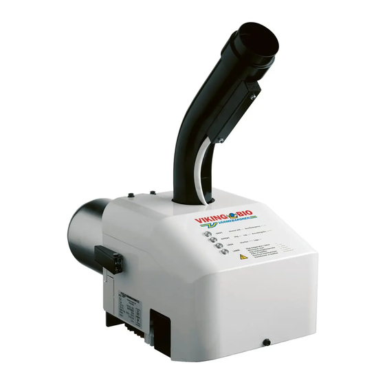
Operation 1101 The Viking BIO is a forward-burning pellet burner for wood pellets. There are four indicators on the burner. By flashing in different ways, they Fuel and air are mixed in a controlled fashion in the burner. This is the ba- provide information about operating phases and alarms. -
Page 6: Installation
Installation 1101 Supply air to boiler room Installation must take place according to existing regula- tions. The installer must familiarise himself with the existing There must be a supply air valve to the boiler room. The valve's free sur- rules. face must correspond to the cross-sectional area of the chimney. -
Page 7: Installation
Installation 1101 Downpipe Feed auger The downpipe is screwed to the body of the burner. The downpipe can be Fit the feed auger motor on the feed auger. Tighten the locking screw well rotated in increments of 22° to obtain a suitable angle to the feed auger. so that the motor does not slip on the feed auger shaft. -
Page 8: Electrical Installation
Electrical installation 1101 Electrical connection When the burner is to control the boiler temperature, the phase supply and control phase must be preceded by over- The electrical installation must be carried out according to heating protection. existing rules under the supervision of a qualified electrician. The burner must be preceded by an all-pole switch, protected with a max. -
Page 9: Electrical Installation
Electrical installation 1101 Connection to Värmebaronen boilers There are electric cables, etc. behind the front panel of the The diagrams below show how the burner is connected to some of Värme- boiler. Check where they are before drilling for any cable baronen's boilers. -
Page 10: Wiring Diagram
Wiring diagram 1101 BLACK BLACK YELLOW ALARM WHITE FEED AUGER TEMP THERMOSTAT START DOSE THERMAL RELAY BLUE BLUE BLACK BLUE L1 B4 T2 T1 L1 B4 T2 T1 2 x 300 W THE FAN’S CONNECTOR (FROM THE CABLE SIDE) 1. Connector for supply thermostat, etc. See electrical installation. 7. -
Page 11: Indicators And Settings
Indicators and settings 1101 OPERATION Normal operation Start delay POWER High Cooling phase Alarm FLAME Start phase Flame Feed auger High temperature in downpipe ALARM Failed start TEMP Thermostat High ambient temperature Fan not working START DOSE Thermal relay Excess pressure, combustion chamber Starter element not working Material of feed auger's pipe - SW2/1 16. -
Page 12: Startup
Startup 1101 Before starting the burner for the first time, check that: to adjust. The chimney draught affects the time it takes for the burner to • it has been installed according to the instructions. establish a flame. Switch SW2/2 is used to set the draught. •... -
Page 13: Adjustment
Adjustment 1101 5. Operating modes. The burner's factory settings allow it to start in most boil- ers. These are not operating settings. They must be adapted High power, 20 kW in each case. Optimum adjustment is possible only using High power Off (SW1/1) flue gas analysis instruments. -
Page 14: Pellet Firing
Pellet firing 1101 The burner's parts in contact with flames are wearing parts that need Flue gas temperature replacement as required. To increase the efficiency and the service life A high flue gas temperature may be because the boiler has not been swept of the grate and inner burner pipe, please observe the following: or there is too much combustion air. -
Page 15: Efficiency
Pellet firing 1101 temperature control is also suitable when the burner has been installed in a wood-fired boiler with accumulator tanks. Efficiency If the burner is preceded by a boiler thermostat, this must be set to its If you take care of your system and adjust it regularly, you will use less maximum value. -
Page 16: Operation, Start To Stop
Operation, start to stop 1101 Operation, start to stop Operation The Viking Bio's operating process is reminiscent of that of an oil burner. • The fan speed is determined by the power set. The 'POWER' indicator One major difference is that the start and stop phases take longer. Under lights up constantly or flashes, depending on the operating mode. -
Page 17: Operation And Maintenance
Operation and maintenance 1101 Sweeping Ash and soot Switch off the power to the burner and detach the plug before Always be careful with ash as it may be smouldering. cleaning or service or before the burner is detached from the boiler. -
Page 18: Safety System
Operation and maintenance 1101 Safety system Resetting the thermal relay The p ellet system's safety system consists of: When the thermal relay on the • overheating protection against excessive boiler temperature. downpipe has been triggered, • thermal relay in downpipe. the 'ALARM' indicator lights up •... -
Page 19: Troubleshooting
Troubleshooting 1101 Troubleshooting Resetting the alarm In the event of a problem, first check all the conditions required for the Switch off the power to the burner for approximately 10 seconds. burner to work: In the event of a fault that requires intervention in the burner, the power must always be switched off before work begins. -
Page 20: Troubleshooting
Troubleshooting 1101 Alarm indicator/alarm Probable cause Action On constantly. Clogged chimney. Check the draught. Sweep if necessary. High temperature in downpipe Too much ash and soot in the burner and combustion Clean the burner and boiler. Reset the thermal relay. chamber. -
Page 21: Component Specification
Component specification 1101 45 46 item art. no. component qty. item art. no. component qty. item art. no. component qty. 10 170090 Static relay 33 700059 Insulating sheet, inner 700064 Gasket, downpipe 31 210019 Circuit board 700060 Gasket, boiler hatch 44 710044 Quick coupler 8 360020 Current transformer 34 700062 Insulating sheet, outer... -
Page 22: Accessories
Accessories 1101 Art. Boiler temperature sensor temperature control via the burner 3310 621 05 58 Mounting plate 300 x 300 mm, with holes for Viking BIO 3320 621 05 59 Conversion set for large wood insertion hatch burn plates and insulation, Vedolux 40/50/CU, Combimax UB 3321 Conversion set for small wood insertion hatch burn plates and insulation, Triomax, Combimax CU and older Combimax UB... - Page 23 1101 Illustrations may differ from actual product Subject to printing/proofreading errors...
- Page 24 Värmebaronen AB reserves the right to change the specification of components, in accordance with its policy of continuous improvement and development, without prior notice. Varmebaronen UK 01786 849 099 11 Back O'Hill, 01786 849 098 www.varmebaronen.org Stirling. FK8 1SH info@varmebaronen.org...
Need help?
Do you have a question about the Viking Bio 20 and is the answer not in the manual?
Questions and answers