Table of Contents
Advertisement
VERSION ACT.11.17
BATTERY HYDRAULIC USER GUIDE
THIS GUIDE COVERS
11c EFORCE 2.0, 14c EFORCE 2.0,
15c EFORCE 2.0, 17c EFORCE 2.0
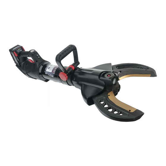
C165 EFORCE 2.0, C185 NXTGEN EFORCE 2.0,
C195 NXTGEN EFORCE 2.0, C236 NXTGEN EFORCE 2.0, All-9
S20, S45-SL EFORCE 2.0, S53 EFORCE 2.0
21/36 EFORCE 2.0, 22/54 EFORCE 2.0
CONCRETE CRUSHER EFORCE 2.0,
DOOR OPENER EFORCE 2.0
2780 CULVER AVE | KETTERING, OHIO 45429 | TEL: 1.937.293.6240 | WWW.GENESISRESCUE.COM
Advertisement
Table of Contents


Need help?
Do you have a question about the 11c EFORCE 2.0 and is the answer not in the manual?
Questions and answers