Table of Contents
Advertisement
VERSION 10-30-2023
SLi TOOL USER MANUAL
RM-013 REV. 2 Rel. Date 10-11-2023
Created by: Cory Johns, April Sova
Approved by Scott Cornell
THIS MANUAL COVERS
11C, 11CRIT, 14C, 15C, 17C, 19C, SC198, SC198NXT GEN, SC240, SC240NXT GEN,
SC385, F7, S44, S49, S54, 21-36 RAM, 22-54 RAM
2780 CULVER AVE. | KETTERING, OHIO 45249 | TEL: 1.937.293.6240 | WWW.GENESISRESCUE.COM
Advertisement
Table of Contents

Related Manuals for Genesis 11C


Summary of Contents for Genesis 11C
- Page 1 Approved by Scott Cornell THIS MANUAL COVERS 11C, 11CRIT, 14C, 15C, 17C, 19C, SC198, SC198NXT GEN, SC240, SC240NXT GEN, SC385, F7, S44, S49, S54, 21-36 RAM, 22-54 RAM 2780 CULVER AVE. | KETTERING, OHIO 45249 | TEL: 1.937.293.6240 | WWW.GENESISRESCUE.COM...
-
Page 2: Table Of Contents
CONTENTS 1. General 1.1 Information on the Operating Instructions 1.2 Explanation of Symbols 1.3 Limitation of Liablity 1.4 Copyright 1.5 Warranty Provisions 1.6 Customer Service 2. Safety 2.1 Intended Use 2.2 Operator Responsibility 2.3 Operating Personnel 2.4 Personal Protective Equipment 2.5 Particular Hazards 2.6 Conduct in Dangerous Situations and Accidents 2.7 Signage... - Page 3 TABLE OF CONTENTS (CONT.) 4.5 Hydraulic Supply 4.6 Electrical Supply, Using a Combi Tool as an Example 4.7 Underwater Use 4.7 Communication Module and Radio Connection 4.8 Operating SLi Equipment 4.9 Device Registration for SLi Rescue Tools 4.10 Accessories 4.11 Replacing Blade Inserts (NXT GEN) 4.12 Replacing the Spreader Tips 5.
- Page 4 TABLE OF CONTENTS (CONT.) 7. Transport, Packaging and Storage 7.1 Safety Instructions 7.2 Transport Inspection 7.3 Symbols on the Packaging 7.4 Dispoal of Packaging 7.5 Storage 8. Installation and Commissioning 8.1 Safety Instructions 8.2 Checks 8.3 Shut-down (End of Work) 8.4 Advantages of Device Registration 9.
-
Page 5: General
1. General 1.1 Information on the Operating Instructions These operating instructions provide information on using SLi equipment. To assure safety at the workplace, always observe all safety and handling instructions contained in this document. When using the equipment at the operation site, please follow the local Health & Safety guidelines and applicable risk assessments. -
Page 6: Explanation Of Symbols
GENERAL 1.2 Explanation of Symbols Warnings In these operating instructions, warnings are identified by symbols. The individual warnings are introduced by signal words expressing the degree of danger. These warnings must be followed to prevent accidents, injury and property damage. DANGER! ...points out an immediately dangerous situation which can cause death or severe injury if it is not avoided. -
Page 7: Limitation Of Liablity
Tips and Recommendations NOTE! ...emphasises useful tips and information for efficient, trouble-free operation. 1.3 Limitation of Liability All information and instructions in these operating instructions were compiled under consideration of the applicable standards and regulations, the current state of technology and our long-standing knowledge and experience. -
Page 8: Warranty Provisions
GENERAL NOTE! Additional information, images and diagrams are available on our website: www.genesisrescue.com 1.5 Warranty Provisions The warranty provisions are included with the sales documentation as a separate document. 1.6 Customer Service Our Customer Service would be happy to provide you with technical information. Phone: 937.293.6240 Fax: 937.293.7049 For SLi Technology &... -
Page 9: Safety
2. Safety This section of the operating instructions presents a comprehensive overview of all important safety aspects for optimal protection of the operating personnel as well as safe, trouble-free operation. Non-observance of the handling and safety instructions presented in these Operating Instructions can result in serious dangers. - Page 10 SAFETY Combi Tools (11C/11CRIT, 14C, 15C, 17C, 19C) • The battery-powered combi tools may be used for the specified purposes of both the cutters and the spreaders. The spreader tips can also be used as a peeling tool. Rescue Rams (21-36, 22-54) •...
-
Page 11: Operator Responsibility
NOTE! SLi devices contain a communication module, which is required for the WLAN, LTE and GPS for communication and location determination. More detailed information on the communication module and the radio connections and channels used can be found in section 4.7. 2.2 Operator Responsibility In addition to the occupational safety information in these operating instructions, the health and safety, accident prevention and environmental prevention, guidelines and regulations applicable... -
Page 12: Operating Personnel
SAFETY 2.3 Operating Personnel The following qualifications for different areas of activity are specified in the operating instructions: • Instructed persons Have been instructed by the operator regarding the tasks they have been assigned and the possible dangers caused by improper actions. •... -
Page 13: Personal Protective Equipment
2.4 Personal Protective Equipment To minimize danger for the operating personnel, wearing personal protectice equipment (PPE) when handling the hydraulic rescue equipment is absolutely mandatory. As a matter of principle, always wear the following protective clothing for all work: Safety Work Clothing Only wear closely fitting work clothing with narrow sleeves and without protruding pieces while working. -
Page 14: Particular Hazards
SAFETY 2.5 Particular Hazards The dangers resulting from the risk assessment are presented in the following section. To minimize potential health hazards and prevent dangerous situations, the safety instructions listed below and the warning instructions in the following chapters of these Operating Instructions must be observed. - Page 15 Noise WARNING! Danger to hearing caused by noise The noise arising in the working area can cause serious damage to the hearing. Therefore: • Wear ear protection during any special kind of work that causes noise. • Only wear ear protection while you are in the danger area. Hydraulic Energy WARNING! Danger due to hydraulic energy!
-
Page 16: Conduct In Dangerous Situations And Accidents
SAFETY 2.6 Conduct in Dangerous Situations and Accidents Preventive measures • Always be prepared for accidents • Always have first-aid equipment (first-aid kit, blankets, etc.) within reach • Familiarize personnel with accident reporting, first aid and rescue equipment • Keep access routes for rescue vehicles open In case of incidents •... -
Page 17: Signage
2.7 Signage The following symbols and instruction panels are located on the equipment. They refer to the immediate environment in which they are displayed. Please note contents of operating instructions Do not use the designated tool until you have read the operating instructions from cover to cover. -
Page 18: Technical Specifications
3. Technical Specifications 3.1 Combi Tools 11C-RIT 11C-RIT Length 32.56 in. 37.13 in. 37.36 in. 38.9 in. 42.36 in. 31.10 in. Width 7.56 in. 9.29 in. 9.29 in. 9.29 in. 10.35 in. 7.56 in. Height 8.98 in. 8.98 in. 8.98 in. -
Page 19: Cutters
3.2 Cutters SC198 SC198NXT GEN SC240 SC240NXT GEN SC385 SC198 SC198NXT GEN SC240 SC240NXT GEN SC385 Length 35.75 in. 35.75 in. 36.85 in. 36.85 in. 39.49 in. 41.97 in. Width 9.29 in. 9.29 in. 9.29 in. 9.29 in. 11.65 in. 11.61 in. -
Page 20: Spreaders
TECHNICAL SPECIFICATIONS 3.3 Spreaders Length 35.16 in. 39.33 in. 40.63 in. Width 9.41 in. 11.10 in. 11.10 in. Height 8.98 in. 8.98 in. 8.98 in. Weight (ready for use) 40.12 lbs. 47.62 lbs. 48.06 lbs. Spreading Width 24.02 in. 28.94 in. 31.7 in. -
Page 21: Rescue Rams
3.4 Rescue Rams 21-36 22-54 21-36 22-54 Length 21.26 in. 23.11 in. Width 6.14 in. 6.14 in. Height 12.64 in. 13.58 in. Weight 40.57 lbs. 47.4 lbs. Pushing Force* 24,953 lbf 24,279 lbf/13,938 lbf Closed Length 21.26 in. 23.11 in. Extended Length 35.75 in. -
Page 22: Structure And Function
4. Structure and Function 4.1 Overview of SLi Equipment Combi Tools Blades (arms) Protective Boots Handle Cylinder Drive/Pump/Oil Reservoir Rocker Switch On/Off Button Light Control Button Rear Handle Battery Cover and Battery Brief Description of Combi Tools Battery-powered combi tools are specially designed rescue equipment for cutting and spreading vehicle body parts. -
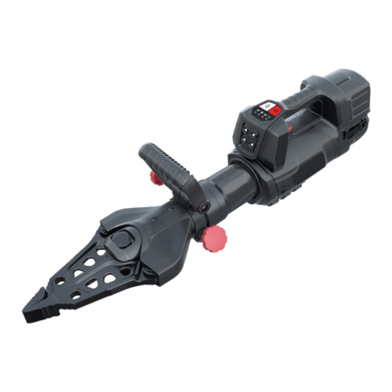
Page 23: Cutter
4.2 Cutter Blades (arms) Protective Cover Handle Cylinder Drive/Pump/Oil Reservoir Rocker Switch On/Off Button Light Control Button Rear Handle Battery Cover and Battery Brief Description of Cutter Battery-powered cutters are specially designed rescue equiment for cutting vehicle body parts. They are used to rescue trapped or enclosed accident victims. The cutter uses include cutting door and roof beams, columns and sills. -
Page 24: Spreaders
STRUCTURE AND FUNCTION 4.3 Spreaders Spreader Tips Spreader Arms Handles Cylinder Drive/Pump/Oil Reservoir Rocker Switch On/Off Button Light Control Button Rear Handle Battery Covers and Battery Brief Description of Spreader Battery-powered spreaders are specially designed rescue equipment for spreading, pressing and pulling. They are used to rescue trapped or enclosed accident victims. The spreaders are mainly suitable for opening doors, and for lifting vehicles and other movable loads. -
Page 25: Rescue Rams
4.4 Rescue Rams Pushing Head Guide Piece Drive/Pump/Oil Reservoir Rocker Switch On/Off Button Light Control Button Handle Battery and Battery Cover Brief Description of Rescue Rams Battery-powered rescue rams are specially designed rescue equipment for pushing away parts of a vehicle body. They are used to rescue trapped or enclosed accident victims. The rescue ram is suitable for tasks such as pushing up steering columns, vehicle roofs and other obstacles. -
Page 26: Hydraulic Supply
WN61000137. The oil does not usually need to be changed, but we recommend changing it after 10 years. An oil change can only be carried out by means of factory servicing at Genesis Rescue Systems or an authorized service partner. -
Page 27: Electrical Supply, Using A Combi Tool As An Example
4.6 Electrical Supply, Using a Combi Tool as an Example Inserting/removing the battery: Connect the battery to the rescue tool by sliding the battery into the battery holder of the tool. Make sure that the Click On/ Click Off of the battery is correctly seated and locked. -
Page 28: Underwater Use
STRUCTURE AND FUNCTION To protect the battery and the electronics, the tool is divided into a wet and dry area. The battery, drive and electronics are protected in the rear area of the housing by the IP 68 battery cover. Using the IP 68 battery cover: For underwater use, replace the IP 54 battery cover with the IP 68 battery cover supplied. -
Page 29: Communication Module And Radio Connection
4.7 Communication Module and Radio Connection The communication module is installed in the rear housing component. This transmits data from the tool to an external output device via WLAN or an LTE connection - depending on the user's choice and the active operating mode. The basic hydraulic functions are always guaranteed by component separation. - Page 30 STRUCTURE AND FUNCTION GNSS Constellation GNSS Signal Designations RNSS Frequency Band (MHz) 1 559 to 1 610 1 559 to 1 610 Galileo 1 559 to 1 610 Galileo 1 164 to 1 215 Galileo 1 164 to 1 215 Galileo 1 215 to 1 300 GLONASS...
- Page 31 4.8 Operating SLi Equipment To start the battery-operated tool, press the on/off switch. The workspace lighting LEDs switch on and the four control LEDs on the control panel briefly light up green; this is a control function. The motor begins to idle. In this state, if the tool is not operated using the rocker switch on the control handle, the drive switches off automatically after 30 seconds and must then be restarted.
-
Page 32: Operating Sli Equipment
SLi device by providing its unique TIN number. If you do not yet have an account in the Genesis Rescue digital world, then you can quickly and easily create your SLi device by clicking on the "Register" button in the top right corner. -
Page 33: Accessories
4.10 Accessories Combi Tools M18 Milwaukee Battery Mechanical Rams Brute Tips RIT Tips DIVEX Bag - Large DIVEX Bag - Small Spot Weld Tips Part No. SPS 270 MK2 SPS 360 MK2 SPS 370 MK2 RIT-TOOL SPS 400 MK2 SPS 480 MK2 Shear Blades 1101470 1101471... -
Page 34: Replacing Blade Inserts (Nxt Gen)
STRUCTURE AND FUNCTION 4.11 Replacing Blade Inserts (NXT GEN) During a change of blades, ensure the cutter is fixed in place. Any movement should be avoided. Replacing the blades requires a soft-face hammer, the tensioning pins supplied, the punch and the blade inserts themselves. -
Page 35: Replacing The Spreader Tips
4.12 Replacing the Spreader Tips The spreader tips of the S49 and the S54 are secured with captive collar pins in the spreader arms. To replace them, the pins must be pushed out. After the tips have been replaced, the collar pins can be pushed back through. -
Page 36: Applications
5. Applications 5.1 Safety Instructions WARNING! Never reach between the blade or spreader arms! WARNING! During any work with battery tools, tensioned parts can break or fly off, thereby endangering people. Uninvolved parties must therefore remain a safe distance away or stay in the danger zone only as long as necessary. -
Page 37: Pushing (Rescue Rams)
CAUTION! Do not sever any parts with loose ends as this can result in personal injury due to parts flying off. ATTENTION! When cutting high-strength vehicle body parts, such as shock absorbers, hinges or steering columns, the shear blades (arms) may cause severe damage. -
Page 38: Pulling (Spreaders, Combi Tools, Rescue Rams)
APPLICATIONS 5.5 Pulling (Spreaders, Combi Tools, Rescue Rams) After the chain set (as described in Chapter 4.7) has been attached to the equipment, spreaders, combi tools and rescue rams can also be used for pulling. For this, the chains must be tightly tensioned and must be tensed only in the pulling direction. To tension the chain, only one lock can be pressed in, so that the chain can be pulled through the chain lock. -
Page 39: Squeezing (Spreaders, Combi Tools)
5.6 Squeezing (Spreaders, Combi Tools) The squeezing of pipes and other hollow profiles takes place by closing the spreader arms. However, with the combi tools, squeezing can only be done in the area of the tips! ATTENTION! Material to be squeezed can suddenly spring away. Do not remain in the working area of the spreading and combi tools! 5.7 Lifting (Spreaders, Combi Tools, Rescue Rams) Spreaders, combi tools and rescue rams can be used for lifting vehicles or other movable loads... -
Page 40: Battery And Charger
6 Battery and Charger 6.1 Charger Technical Data Part No. 8.0 Ah M12-18 FC - 110V RAPIDCHARGER ART.205.407.9 87 min 6.2 Special Safety Instruction WARNING! Do not throw used batteries into domestic waste or into the fire. Your specialist dealer can dispose of your old battery in an environmentally friendly manner. - Page 41 WARNING! Important safety instructions concerning the battery and the charger. • The charger cannot be used to charge non-rechargable batteries. • Do not store batteries together with metal items (risk of short circuit). • Metal parts must not get into the battery insertion slot on the chargers (risk of short circuit).
-
Page 42: Intended Use
BATTERY AND CHARGER 6.3 Intended Use The charger listed in the table is approved for charging the 18V Li-Ion batteries of the M18/V18 system supplied with the battery tool. 6.4 Mains Connection Only connect to single-phase alternating current and only to the mains voltage specified on the rating plate. -
Page 43: Charging Process
6.6 Charging Process LIGHT INDICATORS Continuous Red Charging Slow Flashing Green Approaching Full Charge Continuous Green Charging is Complete Fast Flashing Red Battery is Too Hot/Cold - Charging Will Begin When Battery Reaches Correct Charging Temperature Slow Flashing Red Battery Charge is Pending - Charging WIll Begin When the First Pack is Fully Charged Flashing Red/Green... -
Page 44: Transport, Packaging And Storage
7 Transport, Packaging and Storage 7.1 Safety Instructions CAUTION! Damage due to improper transport! Improper transport can cause considerable property damage. Therefore: • When unloading the packaged pieces, proceed with caution and pay attention to the symbols on the packaging. •... -
Page 45: Symbols On The Packaging
7.3 Symbols on the Packaging Caution - Fragile! Handle the package carefully, do not drop it, throw it, hit it or tie it down. Facing Upwards! The package must always be transported and stored with the arrows pointing upwards. Do not roll or tilt. 7.4 Disposal of Packaging Properly dispose of all packaging materials and parts that have been removed (transport protection) in accordance with local... -
Page 46: Installation And Commissioning
8 Installation and Commissioning 8.1 Safety Instructions WARNING! Danger of injury due to improper operation! Improper operation can cause severe injury or property damage. Therefore, it is absolutely necessary to: • Carry out all work steps according to the information in these operating instructions. -
Page 47: Shut-Down (End Of Work)
SLi Combi Tools, Cutters and Spreaders: • Check the blades (for damage) • Inspect the spreader tips (for damage) • Check the membrane keypad and the rocker switch (function) • Check the handle (fastened securely) • Check the cover plate (damage) •... -
Page 48: Advantages Of Device Registration
8.4 Advantages of Device Registration What are the advantages of device registration for SLi rescue equipment? With the new SLi battery-powered tool series, Genesis Rescue Systems is heralding a digital revolution in the rescue tool market. This series offers more speed, a Milwaulkee compatible 18V battery, with an intuitive design, as well as numerous smart features packed into a robust and submersible housing. -
Page 49: Maintenance
9 Maintenance 9.1 Safety Instruction WARNING! Danger of injury due to defective maintenance work! Improper operation of the tool can cause severe injury or property damage. Therefore, it is absolutely necessary to: • Have all maintenance work carried out by trained specialists. •... -
Page 50: Maintenance After Operation In Humidity
• After use in dirty and/or salt water, we recommend contacting a Genesis service partner for thorough cleaning of the tool. 9.5 Maintenance Schedule For an exact maintenance schedule with inspection intervals, regulations and reports, see DGUV guideline 305-002, point 18 (hydraulically-actuated rescue equipment). -
Page 51: Malfunctions & Faults
10 Malfunctions & Faults Combi Tools & Cutters Malfunction Possible Cause Remedy Tool does not reach full Rocker switches not completely Press the rocker swithces performance pressed to the side completely to the side Combi tool moves in opposite Check valve defective Have the tool checked by an direction under load authorized service center... - Page 52 MALFUNCTIONS & FAULTS Rescue Rams: Malfunction Possible Cause Remedy Tool does not reach full Rocker switches not completely Press the rocker switches performance pressed to the side completely to the side Ram moves in opposite direction Check valve defective Have the tool checked by an under load authorized service center Rescue equipment does not...
-
Page 53: Decommissioning/Recycling
11 Decommissioning/Recycling After its operating life has expired, dispose of the tool properly. However, individual parts can be reused. The hydraulic oil must be drained completely and collected. Note that the hydraulic oil must be disposed of separately! The local disposal requirements are applicable to the disposal of all equipment parts and packaging materials. - Page 54 2023 SLi Tool User Manual Effective 10/10/2023 Form: RM-013 Rev. 2 Updated: 11/8/2023 TO ENSURE ACCURATE PRICING RETRIEVE THE LATEST VERSION FROM THE TOOLBOX. UNAUTHORIZED DISTRIBUTION IS PROHIBITED. REVISION LOG DATE UPDATED BY Release 10/10/2023 April S Changed Images 3.1 (p.18) 11/3/2023 April S Measurement Change (p.18...
Need help?
Do you have a question about the 11C and is the answer not in the manual?
Questions and answers