
Subscribe to Our Youtube Channel
Related Manuals for S&T CAREU U1


Summary of Contents for S&T CAREU U1
- Page 1 CAREU U1 Vehicle Tracker User Guide Version: 1.01 Reference No.: AVL-CU-U1-00-1111UEN Date: June 23, 2011 SYSTEMS & TECHNOLOGY CORP.
-
Page 2: General Information
General Information If any breakdown occurs due to the operation of the described product or users’ improper handling in accordance with the instructions of the document, S&T shall be liable for the General Conditions based on the delivery of the described product and the content of the document. This product is not designed for the use of life support appliances, devices or systems and thence a malfunction of the product might reasonably be expected to make personal injury. -
Page 3: Table Of Contents
1.3. About CAREU U1 .................... 2 1.4. Hardware Architecture ..................3 1.5. Related Document ................... 4 Chapter 2. Taking A Tour of CAREU U1 ............... 5 2.1. Dimensions ...................... 5 2.2. Front View ......................6 2.3. Rear View ......................6 Chapter 3. -
Page 4: Chapter 1. Introduction
CAREU U1 Vehicle Tracker User Guide Chapter 1. Introduction Thank you for your purchasing CAREU U1 GPS Vehicle Tracker. We are very pleased to introduce you our excellent product, and you will enjoy great benefits by applying such a smart device. -
Page 5: Scope
CAREU U1 Vehicle Tracker User Guide 1.2. Scope This document will guides you to start CAREU U1 Vehicle Tracker. However, as this document contains basic device configuration only, please see CAREU U1 Protocol Document for the advanced information. 1.3. About CAREU U1 CAREU U1 GPS Vehicle Tracker transmits the wireless signals such as location, peripheral, and vehicle control data to a control center. -
Page 6: Hardware Architecture
CAREU U1 Vehicle Tracker User Guide 1.4. Hardware Architecture As hardware is concerned, CAREU U1 is comprised of a micro-controller, regulator, GPS receiver, GSM/GPRS modem, G-Force sensor, flash memory data storage, audio interface, I/Os interface, serial ports and LED status indicators. -
Page 7: Related Document
CAREU U1 Vehicle Tracker User Guide 1.5. Related Document [1] CAREU U1 Protocol Document Chapter 1... -
Page 8: Chapter 2. Taking A Tour Of Careu U1
CAREU U1 Vehicle Tracker User Guide Chapter 2. Taking A Tour of CAREU U1 This chapter will guide you to the major connectors of the U1 device. 2.1. Dimensions 108.00 Dimensions: 108mm x 72mm x 31mm Chapter 2... -
Page 9: Front View
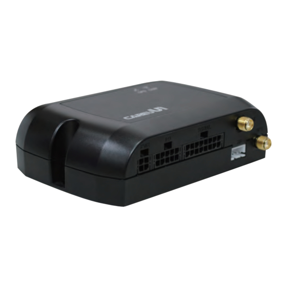
CAREU U1 Vehicle Tracker User Guide 2.2. Front View Name Description Power Connector for Car Battery Input/Output Connector including basic I/O, RS232 SERIAL Serial Connector SMA Connector for GSM External Receiver RF Connector for RF Receiver SMA Connector for GPS External Antenna 2.3. -
Page 10: Chapter 3. Getting Started With Careu U1
CAREU U1 Vehicle Tracker User Guide Chapter 3. Getting Started with CAREU U1 To install the U1 device, follow the instructions below for basic operations. 3.1. Hardware Installation SIM Card Installation • Remove the screw at the bottom of the device to open it. Then you will find the SIM card slot inside. - Page 11 CAREU U1 Vehicle Tracker User Guide GPS Antenna Connection • Connect the GPS antenna to the SMA connector jack on the front side of the device (circled as the illustration below) by completely screwing the GPS antenna's plug connector. • It is recommended that a matching torque 7-10 inch pounds (80-110 N.cm) should be used for the SMA connector.
- Page 12 CAREU U1 Vehicle Tracker User Guide Power, RS-232, and I/O Cable Connection • Connect 4-wire power cable to the power connector on the front side of U1 device (8~30V) • Connect the 8-wire cable to U1 device which enables U1's connection to your system and also to related peripherals.
- Page 13 CAREU U1 Vehicle Tracker User Guide 5. I/O Cable Connection USB Cable Connection G-Sensor Installation Consideration The device uses a 3-axis G-Force sensor to detect the vehicle motion and the impact on the vehicle. The X, Y and Z axis definition will be affected by the location of device installation.
- Page 14 CAREU U1 Vehicle Tracker User Guide Microphone Installation (Optional) Connect the microphone set to the 8-wire cables first. Plug the connector of the 8-wire cable completely into to the seial port on the front side of the device. See the illustration below.
-
Page 15: Connector Pin Assignment
CAREU U1 Vehicle Tracker User Guide 3.2. Connector Pin Assignment Connector Pin Definition 1. PWR Connector Pin# Signal Name Description Electrical Characteristic DC Vin = +8 ~ +30V DC IN Power supply input Normal = 70mA @ 12V Signal ground... - Page 16 CAREU U1 Vehicle Tracker User Guide Pin# Signal Name Description Electrical Characteristic Open-Collector Output 3 Imax = 300mA Output 3 CAN H CAN High VI = 2.75V ~ 4.5V CAN L CAN Low VI = 0.5V ~ 2.25V 3. Serial Connector...
-
Page 17: Usb Device Driver Installation
CAREU U1 Vehicle Tracker User Guide 3.3. USB Device Driver Installation CAREU U1 communicates with your host computer by either RS-232 or USB interface. In some newer editions of Windows XP, the U1 device can be installed as a "virtual COM port"... - Page 18 CAREU U1 Vehicle Tracker User Guide 1. Automatic Installation If the wizard prompts to help you install the software for "STMicroelectronics Virtual COM Port". Select Install the software automatically (Recommended). Press Next button to proceed. The wizard proceeds to install the driver.
- Page 19 CAREU U1 Vehicle Tracker User Guide The installation completes. In [Device Manager], U1 device is included under Ports (COM & LPT) as "STMicroelectronics Virtual COM Port". COM port number is displayed as well. Chapter 3...
- Page 20 CAREU U1 Vehicle Tracker User Guide 2. Manual Installation After you select No, not this time, if the wizard only prompts to help you install software for "USB device", you need to manually install the driver. Select Install from a list or specific location (Advanced).
- Page 21 CAREU U1 Vehicle Tracker User Guide Select Search for the best driver in these locations. Check Include this location in the search. Press Browse button to assign where your U1 device driver locates on your local disk. (U1's USB device driver is free for download on S&T's website at: http:// www.systech.com.tw...
- Page 22 CAREU U1 Vehicle Tracker User Guide Press Next button to proceed. The wizard proceeds to install the driver. Chapter 3...
- Page 23 CAREU U1 Vehicle Tracker User Guide The installation completes. In [Device Manager], U1 device is included under Ports (COM & LPT) as "S&T Tracker". COM port number is displayed as well. Chapter 3...
-
Page 24: Device Configuration
CAREU U1 Vehicle Tracker User Guide 3.4. Device Configuration 1. In Windows XP desktop, click Start | All Programs | Accessories | Communications | HyperTerminal. 2. If you are prompted to input the information of your location, complete them to proceed. - Page 25 CAREU U1 Vehicle Tracker User Guide 6. In the connection that you have just set up, click File | Properties. Select [Connect To] tab. From [Connect using] drop down list, select the correct com port by checking it up at Windows XP's [DeviceManager] as previously mentioned on page and page 20.
- Page 26 CAREU U1 Vehicle Tracker User Guide 7. In File menu, click Properties. Click [Settings] tab. Press ASCII Setup button. 8. In [ASCII Sending] group box. Select both Send line ends with line feeds and Echo typed characters locally. Press OK button.
- Page 27 CAREU U1 Vehicle Tracker User Guide 9. Connect your U1 device to power as mentioned in Power, RS-232, and I/O Cable Connection on page The device startup message will be displayed. 10. In [HyperTerminal] window, type in the command "AT$VERSION?" and press Enter key.
-
Page 28: Communication Settings
CAREU U1 Vehicle Tracker User Guide 3.5. Communication Settings CAREU U1 Vehicle Tracker communicates with your control center by either SMS or GPRS (TCP/UDP). Before the device is installed into a vehicle, communication parameters should be set. SMS Configuration Use AT$SMSDST command to set a SMS control center phone number or short code. - Page 29 AT$APN=internet,username,password (APN=internet, Username=username, Password=password) OK AT$HOSTS=1,0,60.148.19.10,6000 (Server IP address = 60.148.19.10 and Port number =6000) AT$RETRY=5,10 (Message retry settings) AT$IPTYPE=1 (Using TCP/IP mode) AT$GPRSEN=1 (GPRS enable) AT$HB=60,1 (Heartbeat setting) Please refer to CAREU U1 Protocol Document for more command details. Chapter 3...
-
Page 30: Gps Tracking Configurations
CAREU U1 Vehicle Tracker User Guide 3.6. GPS Tracking Configurations After the device communication settings are done, the remote GPS tracking is ready to function. The setting of GPS tracking can be done by using AT$PDSR command. For example, AT$PDSR=1,30,0,0,2,0,0,1,1 (Tracking through GPRS by time interval 30 seconds) For simple testing GPRS, run the TCP Server U-Series software which is provided by S&T. - Page 31 CAREU U1 Vehicle Tracker User Guide For advanced testing, you would need the software IntelliTrac Tracer Plus, which is now available for your download at ftp://ftp.systech.com.tw/AVL/AVLS_TracerPlus/. Please contact your account manager with S&T to request a set of user name and password to access the FTP.
- Page 32 CAREU U1 Vehicle Tracker User Guide The main page of Intelli Fleetweb appears as below: Chapter 3...
-
Page 33: Firmware Upgrade
CAREU U1 Vehicle Tracker User Guide 3.7. Firmware Upgrade CAREU U1's firmware can only be updated through USB interface. With the firmware loader tool provided by S&T, firmware update can be done for the device. Such firmware loader runs on Windows-based systems. To upgrade the firmware, follow the procedure below: (1). -
Page 34: Chapter 4. Technical Specification
CAREU U1 Vehicle Tracker User Guide Chapter 4. Technical Specification Characteristics Dimensions (L x W x H) 108 x 72 x 31mm (With Connector) Weight 165gm Radio Performance Frequency (MHz) Quad-Band 850/900/1800/1900MHz GSM Functionality / GPRS GPRS Mode MultiSlot Class 10... - Page 35 CAREU U1 Vehicle Tracker User Guide Interface I/O I/O Connector 1 Connector, 10pin Serial 1 (configurable): 115200bps Serial Connectors Serial 2 (configurable): 19200bps Serial 3 (configurable): 19200bps Positive Triggers: 2 Input Ports Negative Triggers: 2 Analog Inputs: 2 (0~30V, 12 Bits)
-
Page 36: Chapter 5. About Systems & Technology Corp
CAREU U1 Vehicle Tracker User Guide Chapter 5. About Systems & Technology Corp. CAREU U1 Vehicle Tracker is produced by Systems & Technology Corporation. The company is a key developer and supplier of advanced systems in the Automatic Vehicle Location (AVL), Digital Map and Car Navigation Systems. -
Page 37: Chapter 6. Regulation
CAREU U1 Vehicle Tracker User Guide Chapter 6. Regulation FCC Regulations: 15.19(a)(3): This device complies with part 15 of the FCC Rules. Operation is subject to the following two conditions: (1) This device may not cause harmful interference, and (2) this device must accept any interference received, including interference that may cause undesired operation.
Need help?
Do you have a question about the CAREU U1 and is the answer not in the manual?
Questions and answers