Table of Contents
Advertisement
Quick Links
Advertisement
Table of Contents

Related Manuals for Audix AP62


Summary of Contents for Audix AP62
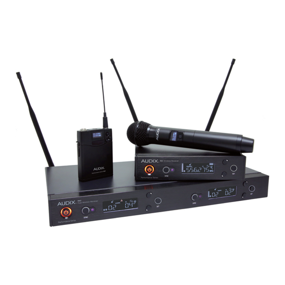
- Page 1 PERFORMANCE SERIES WIRELESS AP61 & AP62 USER GUIDE | SCAN. SYNC. PLAY!
-
Page 2: Table Of Contents
TABLE OF CONTENTS Safety Instructions & Certifications Introduction Quick Set Up Guide R61 Receiver Front Panel R61 Receiver Back Panel R61 LCD Display H60 Handheld Transmitter B60 Bodypack Transmitter Receiver Operating Instructions / Menu Functions Using the H60 Handheld Transmitter Using the B60 Bodypack Transmitter Performance Tips Rackmounts... -
Page 3: Safety Instructions & Certifications
Keep away from water, moisture, heat generating devices and direct sunlight Clean only with dry cloth Do not block the receiver from ventilation Use only with accessories produced by Audix Operate and store in a safe temperature range 0°C (32°F) - 43°C (110°F) CERTIFICATIONS This product complies with FCC Part 74 regulations and conforms to CE standards. -
Page 4: Introduction
INTRODUCTION Congratulations on the purchase of the Performance Series Wireless system from Audix! Your system is jam packed with features that will enable you to fine-tune the system as needed. However, the best part of our design is that the system is simple to use. For most applications, simply refer to the Quick Set Up Guide to get up and running (pgs 4-7). -
Page 5: Quick Set Up Guide
QUICK SET UP GUIDE Follow these instructions to get up and running in very little time. 1. Install 2 AA batteries in the handheld transmitter and bodypack. Refer to the diagrams on the equipment to ensure batteries are positioned correctly. a.) Handheld transmitter: Unscrew bottom portion of the transmitter to expose battery holder. - Page 6 3. Connect power supply. Loop cable through the metal strain relief as shown above prior to connecting power supply to receiver. Plug into power outlet. 4. Connect receiver to mixer or amplifier. Make sure audio levels on the mixer are muted or off.
- Page 7 QUICK SET UP GUIDE 6. Turn on receiver. 7. On receiver, press and hold the UP or DOWN button to trigger Scan for a clear Group/Channel. After 8-20 seconds a Group/Channel˝ will appear on the receiver. 8. Sync handheld transmitter to receiver.
- Page 8 MULTIPLE SYSTEMS Setting up multiple systems utilizes the Scan – Sync functions described to the left. In general, compatible channels for synchronized use are organized by Group. (See the Group/Channel chart on page 27.) Be sure all receivers and transmitters are powered OFF. 1.
-
Page 9: R61 Receiver Front Panel
FRONT PANEL R61 SINGLE RECEIVER R62 DUAL RECEIVER POWER switch. Press for instant ON. DOWN button. Only active in Menu Press and hold for 3 seconds to turn mode. Scrolls backwards through system OFF. menus. Also acts as hot key for autoscan when pushed and held. -
Page 10: R61 Receiver Back Panel
BACK PANEL R61 SINGLE RECEIVER R62 DUAL RECEIVER BNC connector for Antenna B. Metal strain relief. Allows power cable to loop through for added security. Ground lift switch to help eliminate ground loops or noise from DC power jack for external other sources. -
Page 11: R61 Lcd Display
R61 LCD DISPLAY RF (Radio Frequency). Displays RF Displays Level (receiver gain) or signal strength. Squelch (see Menu Functions, pg 14). AF (Audio Frequency). Displays audio Battery level. signal strength. 4 bars = Up to 14 hours 3 bars = 9 hours Indicates whether receiver is 2 bars = 7 hours unlocked or locked for security. -
Page 12: H60 Handheld Transmitter
H60 TRANSMITTER - HANDHELD The H60 is a 64 MHz wide spectrum transmitter. It covers the 522 mHz - 586 mHz frequency group (pg 27). Grill ball. Protects capsule. Power ON/OFF and MUTE button. Replaceable part. Battery cover. Must be opened to Capsule housing. - Page 13 H60 TRANSMITTER - BATTERY COMPARTMENT Houses AA batteries (see Quick Set Up Dip switch to choose between Guide for installation instructions, pg 4). 40 Milliwatt (HI) and 10 Milliwatt (LO) power transmission. H60 TRANSMITTER - TOP Dip switch with choice of 3 output gain settings for capsule (0 dB, -6 dB, -12 dB).
-
Page 14: B60 Bodypack Transmitter
B60 BODYPACK - FRONT PANEL The B60 is a 64 MHz wide spectrum transmitter. It covers the 522 mHz - 586 mHz frequency group (pg 27). Bottom Infrared panel. Point towards the SYNC Antenna. Plug into bodypack and button on the receiver when locking thread on and off. -
Page 15: Receiver Operating Instructions / Menu Functions
RECEIVER OPERATING INSTRUCTIONS By understanding the menu structure it is easy to operate and make adjustments to the system. GROUP (1-10) CHANNEL (1-7) LEVEL (-12 to +9) SQUELCH (5 – 45) DISPLAY LOCK (ON, OFF) (FREQUENCY, CHANNEL, SQUELCH, LEVEL) PILOT (ON, OFF) SCAN (SCAN FOR NAME OPEN FREQUENCY) - Page 16 This setting allows for additional gain control over the receiver. The factory setting is +6, a good gain setting for Audix dynamic microphones. The VX5 condenser microphone has much more output than a dynamic microphone and is better suited in the -6 or -9 range.
- Page 17 The Pilot should be left ON and only be turned OFF temporarily if troubleshooting the system for problems. SCAN The option to perform a scan for a clear channel. The Audix Performance Series Wireless Scan feature performs a scan to find clear and open frequencies as well as compatible frequencies when using multiple systems.
- Page 18 NAME This function allows the receiver to be given a unique name. There are six characters available. Scroll to the NAME˝ display on the menu and press SET. The display will move to the first character and blink. Scroll through the characters by pressing the UP button and there will be a choice of letters, numbers or symbols.
-
Page 19: Using The H60 Handheld Transmitter
Once the desired frequency is displayed, press SET and the second set of three digits will flash (for example, 546.500 with 500˝ flashing). Use the UP or DOWN button to change the number by increments of .025. For example, if starting at 545.500, press the UP key four times and it will read 545.600. - Page 20 CONTROLLING DISTORTION Audix capsules are designed to handle very high sound pressure levels without distortion. If distortion is detected, try to minimize or eliminate it from the mixing console by turning down the trim and gain controls. If distortion persists, there is a gain setting at the capsule.
-
Page 21: Using The B60 Bodypack Transmitter
USING THE B60 BODYPACK TRANSMITTER There are three buttons that control the menu functions—SET, UP (forward) and DOWN (reverse). The functions controlled by the buttons are RF AMP, GAIN and LOCK. There are 3 menu functions: RF AMP, GAIN, LOCK. RF AMP This controls the level of the RF output. - Page 22 LOCK This disables the POWER button from being active. This prevents the bodypack from being accidentally turned off or muted. TO SET LOCK Press and hold the SET button until RF AMP˝ appears on the display. Press the UP button twice and LOCK˝...
-
Page 23: Performance Tips
The bodypack uses a mini 3-pin XLR connector for all microphones. Other brands of microphones can be used with the Audix Performance Series Wireless system; however, it will be necessary to rewire the microphone connector to a mini 3-pin XLR (f ). In this case,... -
Page 24: Rackmounts
R62 two channel receiver into a rack space. Note: Antennas must single 19 inch rack space. remain rear mounted when using this rackmount. RMT 42 Kit Included accessory with AP42 and AP62 systems. Includes RMT42 rackmount and BNC cables for front mounting antennas. -
Page 25: Rackmount Installation
RACKMOUNT INSTALLATION RMT 4161 Holes for rackmount screws Machine screw The holes for attaching rackmounts are located on the sides of the receiver. The rackmounts are attached with two Phillips head screws and are intended to lay over the Torx machine screw that holds the receiver enclosure together. For additional support, the Torx screw may be removed and used as one of the fastening screws for the rackmount. - Page 26 RMT 241 Using the larger Phillips head screw, fasten the metal rackmount ears to the outside of each receiver. Fasten the flat connecting metal piece to the inside of each receiver. Place the two receivers together and line up the holes in order to adjoin the two pieces.
-
Page 27: Troubleshooting
TROUBLESHOOTING PROBLEM POSSIBLE CAUSE CORRECTIVE ACTION Check your power cord to make sure it's plugged Receiver won’t power up Bad connection into the outlet and receiver correctly Make sure they are installed correctly (pg 4) or Batteries check the battery life indicator Transmitter will on the transmitter not power up... -
Page 28: Group/Channel Charts
R61 AND R62 GROUP/CHANNEL CHART GROUP 583.475 585.575 584.500 584.675 584.400 584.825 583.350 584.675 585.375 584.400 583.075 584.850 578.125 582.600 582.350 579.125 581.600 582.600 584.500 582.350 582.450 559.600 571.450 579.400 581.475 578.625 573.825 581.750 581.150 581.475 581.625 558.975 565.600 571.600 579.125 574.475 572.800... -
Page 29: Specifications
SPECIFICATIONS R61/R62 Receiver Frequency Range 522 MHz – 586 MHz Bandwidth 64 MHz Compatible Systems Up to 24 systems (R61) / 12 systems (R62) simultaneous use Switchable Frequencies 207 Pre-coordinated frequencies Manual Mode 2560 Tunable frequencies (spaced 25 kHz apart) Frequency Response 45 Hz –... - Page 30 H60 Handheld Transmitter 10 mW, 40 mW RF Power Output 64 MHz Frequency Bandwidth 0 dB, -6 dB, -12 dB Gain Controls Input Connector 2 AA 1.5 V Batteries Included 110 mA typical Current Consumption Approximately 14 hours Battery Life (depending on battery type and usage) Input Impedance >140 dB (depending on capsule)
- Page 31 503.682.6933 ©2017 Audix Corporation All Rights Reserved. Audix and the Audix Logo are trademarks of Audix Corporation.
Need help?
Do you have a question about the AP62 and is the answer not in the manual?
Questions and answers