Table of Contents
Advertisement
Quick Links
Using FrSky FLD-02 + battery level sensor FrSky FBVS01 + FrSky
1.1 Specifications of FrSky FLD-02 :
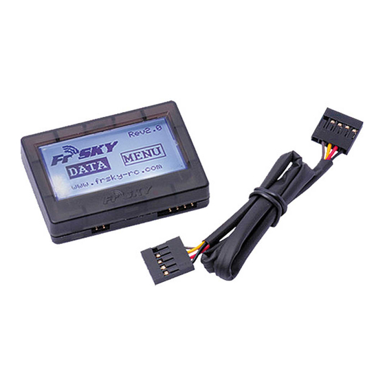
Model: FLD-02
Compatibility: FrSky DFT, DJT and DHT
Dimensions: 55*40*12mm
Screen resolution: 128*64
Backlight: yes, light-cyan
Power: from TX
1.2 Features:
1) Shows data from any compatible sensors connected to RX
2) Programmable alarms
3) Upgradable firmware
2 Quick start:
Connect FrSky FLD-02 to FRSky TX module using the cable supplied with FLD-02. Maintain polarity:
black wire means - ground. Make sure that both switches of FRSky TX module are at "OFF" position.
3 Screen structure:
3.1 Main screen:
*note: you can scroll through buttons|values|digits by rotating upper button to either direction. Short
button press would choose|confirm value. Turning and keeping button for more than 1 second at
either end would set the cursor to the next location in more-than-one digit cell.
3.2 «MENU» Screen
D8R-Ii Receiver. Short manual.
FrSky logo
Firmware version
«DATA» button
«MENU» (settings) button
FrSky website
Blаde: # of blades
Volt ratio: voltage divider on A1 (left cell) & A2 (right
cell) ports
Unit Set: Speed (KPH | MPH)
Temperature: (C | F)
Altitude: (meter | feet)
Alarm Set: alarm setup for A1_1/2, A2_1/2, RSSI_1/2
Alexander "Datos"
«http://forum.modelka.com.ua»
Advertisement
Table of Contents

Subscribe to Our Youtube Channel
Related Manuals for FrSky FLD-02


Summary of Contents for FrSky FLD-02
- Page 1 2 Quick start: Connect FrSky FLD-02 to FRSky TX module using the cable supplied with FLD-02. Maintain polarity: black wire means - ground. Make sure that both switches of FRSky TX module are at “OFF” position. 3 Screen structure: 3.1 Main screen:...
- Page 2 А1 pin receiver data from a sensor. G stands for Ground. Therefore, if there is a bridge between X and A1 pins – telemetry screen FLD-02 would show the inner RX voltage in the left cell “A1 & A2 Voltage” (look at section 3.3.1 of this manual) The readings of this cell A1 (left) on “DATA Screen 1”...
- Page 3 3.2.2 FBVS01 external battery level telemetry sensor This sensor has 3 voltage dividers - soldering pins: 1S (1-2 cell LiPO max. Divider for FLD- 02 = 2), 2S (1-4 cell LiPO max. Divider = 4), 3S (1-6 cell LiPO max. Divider = 6). Initially, red wire that goes to the battery is soldered to 3S pin on board, i.e.
- Page 4 3.3.2 How to setup an alarm for battery sensor readings (3-cell LiPO, connected to A2 telemetry RX port) In order to program low-battery alarm at a certain battery level, you should go to “MENU” Screen (section 3.2 of this manual) and than in “Alarm Set” section choose A2_1 and enter the following values underneath: 1 <...
- Page 5 3.3.5 Экран-3 Total Voltage Voltage for each cell *note: this screen would only be shown if FLVS-01 sensor is connected. Otherwise, Screen-4 would follow Screen-2 directly. 3.3.6 Screen-4 Acceleration X/Y/Z Longitude & Latitude (GPS-data)
Need help?
Do you have a question about the FLD-02 and is the answer not in the manual?
Questions and answers