RTS BTR-240 User Manual
Preliminary
Hide thumbs
Also See for BTR-240:
- Operating manual (86 pages) ,
- Quick start manual (2 pages) ,
- Quick start quide (2 pages)
Table of Contents
Advertisement
Quick Links
Download this manual
See also:
Operating Manual
RTS Model BTR-240
Base Station
Owners / Users Manual
(Preliminary Information)
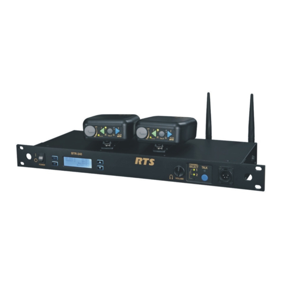
General Description
The RTS model BTR-240 base station
transceiver is a rack mountable, full-duplex,
wireless intercom radio. The base station
provides a central relay location which
handles the audio traffic between the TR-
240 beltpacks.
A BTR-240 base station can be used to
support up to eight full-duplex wireless TR-
240 beltpacks and many more for beltpacks
in push-to-transmit mode.
The BTR-240 uses the IEEE 802.11b
technology to transmit / receive within one
channel of the 1 – 11 (2.412 to 2.462 GHz)
allowable channels of the 2.4 GHz ISM
band. Operation of the BTR-240 is license
free.
The typical line-of-sight distances for the
system may be 300 feet.
The transmit and receive antennas are
connected via unique reverse TNC
connectors on the rear panel of the unit.
BTR-240 Users Manual - Preliminary
Rev D – 4 / 18 / 2011
The BTR-240 is powered via a 12 – 15 VDC
receptacle on the rear panel. A 12 VDC
power supply is supplied with the BTR-240.
The front panel LCD display and buttons
allow the following menus to be obtained:
• RF operating channel
• Microphone gain
• Sidetone level
• Transmit squelch setting
• 2W / 4W intercom type settings and
levels
• Auxiliary In / Out settings and levels.
• Speaker output setting and level.
The front panel also has an on/off power
control. A talk button, talk light, channel
select button, channel select lights, and
volume are also available for a user at the
base station local headset.
Page 1 of 8
Advertisement
Table of Contents

Related Manuals for RTS BTR-240


Summary of Contents for RTS BTR-240
- Page 1 The BTR-240 is powered via a 12 – 15 VDC RTS Model BTR-240 receptacle on the rear panel. A 12 VDC Base Station power supply is supplied with the BTR-240. The front panel LCD display and buttons allow the following menus to be obtained: •...
- Page 2 LCD. active. 9. Local Headset Connector – Male XLR connector for Telex units, female XLR connector for RTS units. A dynamic or electret headset microphone is automatically detected. BTR-240 Users Manual - Preliminary Page 2 of 8...
- Page 3 Amps to power the base station from a D.C. options. source. 4-Wire – an RJ-11jack compatible with 9. Chassis Ground –grounding point of the base “Matrix” type intercom systems. station. BTR-240 Users Manual - Preliminary Page 3 of 8 Rev D – 4 / 18 / 2011...
- Page 4 Operation remembered and the unit will continue to boot on the same channel until it is set differently by When the BTR-240 is turned on, the backlight the user. of the LCD and menu buttons will illuminate to indicate power. The unit takes approximately...
- Page 5 LCD to • Microphone and Sidetone Levels the “Local Headset” option and pressing the <Set> button. BTR-240 Users Manual - Preliminary Page 5 of 8 Rev D – 4 / 18 / 2011...
- Page 6 “set” mode and change levels, press <Up> or <Down> to select a different level for adjustment, or press <Menu> to go back a menu screen. BTR-240 Users Manual - Preliminary Page 6 of 8 Rev D – 4 / 18 / 2011...
- Page 7 4. This device must not be co-located or operated in conjunction with any other antenna or transmitter. BTR-240 Users Manual - Preliminary Page 7 of 8 Rev D – 4 / 18 / 2011...
- Page 8 ATTENTION: Tout changement ou modification non expressément approuvée par la partie responsable de la conformité pourraient annuler l'autorité de l'utilisateur à utiliser cet équipement. BTR-240 Users Manual - Preliminary Page 8 of 8 Rev D – 4 / 18 / 2011...
Need help?
Do you have a question about the BTR-240 and is the answer not in the manual?
Questions and answers