Table of Contents
Advertisement
Quick Links
Download this manual
See also:
Installation Manual
Advertisement
Table of Contents

Related Manuals for DARIM VISION PVE400

Summary of Contents for DARIM VISION PVE400
- Page 1 User’s Guide Rev. 1.3a May 30, 2008 Copyright © 2007-2008 Darim Vision Co, All Rights Reserved...
- Page 2 Throughout this manual, we make reference to product names that are trademarks of other companies. We are using these names for identification purposes only, with no intention of infringement of the trademarks. Copyright © 2007-2008 Darim Vision Co, All Rights Reserved...
-
Page 3: Table Of Contents
SPECIFICATIONS ..............................- 29 - PVE400 T ........................- 29 - ECHNICAL SPECIFICATION PVE-CAM ....................... - 29 - TECHNICAL SPECIFICATION ............................- 30 - ONNECTORS PIN OUT ............................- 32 - IST OF ACCESSORIES Copyright © 2007-2008 Darim Vision Co, All Rights Reserved... -
Page 4: General Information
Field-replaceable Lithium-ion battery, specifically designed to meet the needs of harsh operating conditions or critical/emergency response teams. The PVE400 can be managed and monitored from either an Incident Response Command Post or from a Central Operations Control Centre – delivering real-time video and audio information from outdoor environments back to a centrally managed control location in order to communicate true “Point-of-View”... -
Page 5: Requirements
• OS: Microsoft® Windows® XP Home or Pro, Windows® Vista The rest of this document contains important operating instructions for the PVE400 unit. Be sure to read all the applicable sections carefully before proceeding. Copyright © 2007-2008 Darim Vision Co, All Rights Reserved... -
Page 6: Installation Steps
PVE400 USER’S GUIDE 2. INSTALLATION STEPS This chapter describes the installation procedure of the PVE400 accessories. Figure 2. PVE400 interface Copyright © 2007-2008 Darim Vision Co, All Rights Reserved - 6 -... -
Page 7: Installing Antenna
Do not rotate antenna itself. Figure 3. Attaching the supplied antenna Warning: The only supplied antenna with 2.0dBi gain is certified to use with PVE400 when the device is used as wearable. 2.2 Installing the camera PVE400 is bundled with 1/3"... -
Page 8: Using Other Video/Audio Source
PVE400 from accidental shortage. The standard electret microphone can be connected to the audio jack. PVE400 will provide 1.1V DC bias for the microphone on the same connector. See also the table in section 8.3 for the connector pin out, if the custom cable is needed. -
Page 9: Battery Replacement
Saft 1S1P MP 176065. Une autre batterie peut provoquer un incendie ou une explosion. 2.7 Using wired network connection PVE400 has a standard 10/100Base-T Ethernet adapter accessible via AUX connector. Since AUX connector is also used for RS232 interface and external power, a special cable is required to use Ethernet function. -
Page 10: Getting Connected
PVE400 USER’S GUIDE 3. GETTING CONNECTED PVE400 has a built-in web server. The whole configuration can be done using Internet Browser; no other special software is required. All parameters on the configuration pages are stored in Non-Volatile RAM (FLASH), so turning off the power will not reset them. New parameters will be stored by clicking the [Apply] button with verification that all parameters are valid. - Page 11 Clicking the [Apply] button will save all changes to Non-Volatile RAM and restart all services. Clicking the [Reboot] button will cause complete software and hardware reboot, during this time the communication will be lost for about 90 seconds. Copyright © 2007-2008 Darim Vision Co, All Rights Reserved - 11 -...
-
Page 12: Network Configuration
The Ethernet IP mode drop-down list allows you to select the IP configurations parameters: DHCP Server - PVE400 has an internal DHCP server and can provide IP address for other devices connected to PVE400. If this mode is selected, specify the address range in the DHCP Server Starting IP Address and DHCP Server Ending IP Address fields. - Page 13 PVE400 USER’S GUIDE DHCP Client – in this mode PVE400 will request IP address and all network configurations from the external DHCP server. If IP address has been successfully obtained, it will be shown in “Ethernet IP Address” line as read only (gray).
-
Page 14: Wireless Connection Configuration
(ESSID) of the wireless interface. During the operation in the AD-Hoc or Client mode, ESSID is the name of the Wireless Access Point for the device to be associated with. Additionally, in the ad-hoc mode, one must provide the Wireless AP MAC Address. Copyright © 2007-2008 Darim Vision Co, All Rights Reserved - 14 -... - Page 15 Type in the full URL in the field, for example ftp://192.168.1.253/client.cer. Press the [Load Certificate] button to complete the load operation. If any changes have been made on this page, click the [Apply] button; otherwise simply select the other tab. Copyright © 2007-2008 Darim Vision Co, All Rights Reserved - 15 -...
-
Page 16: Video And Audio Configuration
The CONFIG page contains all Video/Audio related parameters. Figure 8. Video and Audio configuration page PVE400 can operate in PAL or NTSC mode. The Video Standard field represents the current selection of the video standard. Using the Capture Resolution drop-down list you can choose a required resolution. Currently four different resolutions are supported. -
Page 17: Viewing Video
PVE400 USER’S GUIDE PVE400 uses MPEG4 compression for video. When the wireless connection is used, the video bit rate is limited by the throughput of the wireless network, which is about 1Mbps in case of using WMC6300/7300 cards. This bandwidth will be shared by all users in the network. - Page 18 The third option is using Darim’s Video Spider software, it can be purchased separately. The Video Spider software will allow to monitor and record data from multiple PVE400 units. The Video Spider software has Client-Server architecture, allowing multiple client computers to connect to the server (or multiple servers).
-
Page 19: Monitoring The Battery Status
The capacity counter will show an accurate value only if the battery has been fully charged inside the PVE400 unit. If a new battery is installed, the capacity calculation will be done only based on the voltage information (with 20% accuracy) To update the information on this page, press the [Refresh] button or simply click the tab again. -
Page 20: Upgrading Firmware
If the status after the upgrade reports an error, check the network connection to upgrade site, if it can be accessed from the network segment of the working PVE400. The firmware image can be downloaded from the Internet and placed to a local FTP site, to make easy access from PVE400. -
Page 21: Status Leds
Three color indicators one the top cap (Figure 2 - 6,7,8) will show status of operation. Green LED will turn on as soon PVE400 is ready for operation. If remote client connected to PVE and receiving video stream, LED will start blinking. -
Page 22: Advanced Configuration
PVE400 unit, either for configuring or requesting a video stream. By default, the list is empty. Any device can be connected to the PVE400 unit. However, once an address is added to the list, all other devices are automatically prevented from accessing with the exception of those devices from the list. -
Page 23: Ip Router
4.2 IP router As the PVE400 unit has two network interfaces, it can act as a wireless router. By default IP forwarding is enabled. All you need is to configure IP settings of the external devices, so that they will be in the same IP segment as PVE400 Ethernet, and PVE400 will be as the default gateway for them. -
Page 24: Customer Service Information
Or send an e-mail to usasales@darim.com. The Regional Representative will be the first line of support for the product. The latest version of the PVE400 User’s Guide is available at www.darimcctv.com/ftp/PVE/PVE400-UG.pdf. Copyright © 2007-2008 Darim Vision Co, All Rights Reserved... -
Page 25: Product Warranty Information
This warranty is in lieu of any other warranty expressed or implied. In no event shall we be held liable for incidental or consequential damages, such as lost revenue or lost business opportunities arising from the purchase of this product. Copyright © 2007-2008 Darim Vision Co, All Rights Reserved - 25 -... -
Page 26: Regulatory Information
Connect the equipment into an outlet on a circuit different from that to which the receiver is connected. • Consult the supplier of PVE400 or an experienced radio/TV technician for help. Changes or modifications not expressly approved in writing by Darim Vision Co. may void the user's authority to operate this equipment. FCC ID: QTF-PVE400... -
Page 27: Ce Mark Certification
The following is an example of the CE Marking on the product label: The alert symbol indicates that PVE400 is not certified to operate in France. Outdoor use in France is restricted to 10mW EIRP for band 2454 -2483.5 MHz... -
Page 28: Rohs
PVE400 USER’S GUIDE 7.5 RoHS The PVE400 complies with the European RoHS directive, 200/95/EC, and Chinese RoHS regulations, EFUP-50 (see bundled sheet TTT table - CMM hazardous table content). 7.6 WEEE Directive The European Union has enacted a Directive 2002/96/EC on Waste Electrical and Electronic Equipment (WEEE Directive). -
Page 29: Specifications
12VDC Operating current: 90mA Operating temperature: 14˚ F~122˚ F (-10˚ C~ + 50˚ C) Measurement: 0.83” x 2.84” (21mm x 72mm) Weight: 0,485lb (220g) Cable length: 4’ (1.2M) Copyright © 2007-2008 Darim Vision Co, All Rights Reserved - 29 -... -
Page 30: Connectors Pin Out
Mating male connector Fischer S1031 A010-140+ A/V connector Pin # Designation Video in Audio input Audio ground +12V out Video ground/power ground Mating male connector Fischer S102 A054-140+ www.fischerconnectors.com Copyright © 2007-2008 Darim Vision Co, All Rights Reserved - 30 -... - Page 31 RJ45 pin # Purpose green Ethernet white/orange Ethernet white/brown reserved white/green Ethernet orange Ethernet white/blue RS232 common brown RS232 Rx blue RS232 Tx Note Ethernet wired as straight through (T568B). Copyright © 2007-2008 Darim Vision Co, All Rights Reserved - 31 -...
-
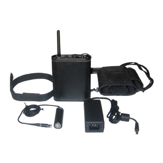
Page 32: List Of Accessories
PVE-NCC Nylon Carrying Case with strap an belt loop PVE-BT Spare battery (same as supplied with PVE400) PVE-PS AC to DC Power Supply to power PVE400 and charge internal battery PVE-RPC (US) US type Power cord for PVE-PS PVE-RPC (EUR)
Need help?
Do you have a question about the PVE400 and is the answer not in the manual?
Questions and answers