
Summary of Contents for MM MI114
-
Page 1: User Manual
MI114 Batching Controller User Manual MI114R2 www.meltrons.com info@meltrons.com Millennium Mechatronics Limited, PO Box 59187, Dr, Mangere, Manukau, Auckland 2151... -
Page 3: Table Of Contents
MI114 User Manual Contents Chapter 1 Profile ---------------------------------------------------------------------------------------------------------------2 Chapter 2 Main Parameters ---------------------------------------------------------------------------------------------------3 Chapter 3 Installation, Interface and Data Format -------------------------------------------------------------------------4 I. Diagram of Front and Back Function Buttons of Indicator ------------------------------------------------------4 II. Connection of Load Cell and Indicator ----------------------------------------------------------------------------6 III. -
Page 4: Chapter 1 Profile
MI114 User Manual Chapter 1 Profile MI114 uses an advanced delta-sigma A/D converter to achieve a higher speed and higher accuracy for batching or packing systems. The MI114 single chip microprocessor and high-speed Σ-△A/D switch technology performs conversions and displays weight, with the maximum conversion speed of up to 80 times/second. The display can be easily connected to the strain gauge based load cells to form batching scales, packing scale, weighing control systems etc , where high-speed and high precision weighing are required. -
Page 5: Chapter 2 Main Parameters
MI114 User Manual Chapter 2 Main Parameters 1. Type: MI114 weighing indicator 2. Accuracy: Class 3, n=3000 3. Input signal range: -19mV~ +19mV ≤0.008%F.S 4. Nonlinearity: 1- 8, 350Ω load cell 5. No. of connected load cell: 6. Power supply for load cell: DC:5V;350mA... -
Page 6: Chapter 3 Installation, Interface And Data Format
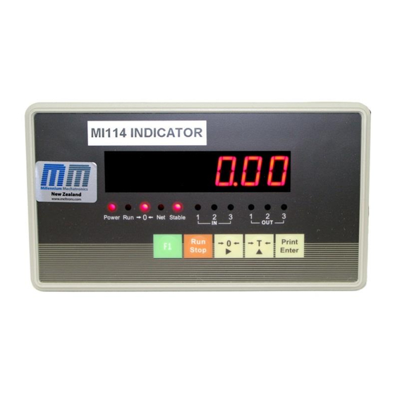
MI114 User Manual Chapter 3 Installation, Interface and Data Format Diagram of Front and Back Function Buttons of Indicator Figure 3-1 Diagram of Front Function Buttons The meanings of the 11 indicating lamps on display panel are as follows (from left to right):... - Page 7 +1 2V 13 OV l10-230V 50/60Hz AC power supply Output terminal lnput terminal GND RxD TxD Y ON OFF DP- AO EX+SEN+SEN-EX-SlG+S G-GND Load cell interface Calibration switch Communication/Large-screen/ Analog output i nterface Figure Diagram or Back Function Buttons jumper jumper 485/232 485/232...
-
Page 8: Connection Of Load Cell And Indicator
SIG-: Negative signal GND: Ground Tip: If a 4 load cell cable is used to connect to MI114, the pins of “EX+” and “SEN+”, “SEN-” and “EX- ” in Figure 3-4 must be short-connected. Otherwise, the indicator cannot be calibrated and weigh normally. -
Page 9: Analog Output
2. Command response mode: For detailed format, please see Annex 3 VI. Analog output MI114 indicator can choose 3 analog output modes: 0~5V, 0~10V voltage signal output and 4~20 mA current signal output (It can be also be adjusted to 0~20 mA . The electric current loop adopts the internal electrical power supply mode, the output mode is selected by jumper JM3~JM5 (See Figure 3-3) on the... -
Page 10: Print And Storage
MI114 Manual 0—10V Down Left Calibration method for analog output The zero point value of analog output and full scale value are in direct proportion to corresponding DA code (See Table 4-3, instructions of [SEt 1] parameter 12 and 13). The parameter 12 and parameter 13 can be corrected by calculation according to the analog output error. -
Page 11: Chapter 4 Parameter Setting And Calibration
MI114 Manual Chapter 4 Parameter Setting and Calibration If there is no special instruction for parameter setting, the button functions are as follows: [F1] button: exit from parameter setting [Operation] button: the current setting is not saved, and return to the previous parameter... - Page 12 MI114 Manual Press [Zero setting] button to move the current [d**.**.**] Current date setting flicker bit, press [Tare] button to modify parameter value Press [Zero setting] button to move the current [t**.**.**] Current time setting flicker bit, press [Tare] button to modify parameter...
-
Page 13: Set 1】General Parameters
MI114 Manual It can only be inquired, but not changed. Accumulated frequency of [n 3 ****] Channel 3 It can only be inquired, but not changed. Accumulated weight of Channel [A******] The following parameters are same with the latter [d**.**.**] Setting of current date part of Table 1. -
Page 14: Set 2] Control Parameters
MI114 Manual Communication Mode: 0-command response mode (Refer to Chapter 3); It won’t be displayed when [tod communication is not required. 1-continuous send mode 2-connect to serial printer Automatic accumulated print: 0-automatic accumulation Accumulation and print conditions [AtP should be set appropriately . - Page 15 MI114 Manual Mode 0, 1 (Additive mode or subtraction mode for 1 kind of batching material) Advanced Control Parameters A-quick or slow feed status 0: When quick feeding, only the quick feed is opened. 1: When quick feeding, both the quick and slow feed are opened simultaneously.
- Page 16 MI114 Manual 0.0~9.9 seconds time Mode 0: discharge over delay Mode 1: qualified output time 0.0~9.9 seconds re-feed delay Whether to print this parameter: [Prt 0:No. It won’t be displayed when there is no printer. 1: Yes. Mode 2 (Additive mode for 2 kinds of batching) Advanced Control Parameters A -...
- Page 17 MI114 Manual 0.0~9.9 seconds material 2 feed over delay This item won’t be displayed when there is no 0.0~9.9 seconds gradual feed output gradual feed. time It won’t be displayed when there is no gradual 0.0~9.9 seconds gradual feed interval feed.
-
Page 18: Record Print [Set 3]
MI114 Manual Calculation Delay (0~9.9) Seconds: The indicator has no action within t2 after t1 is calculated, wait with delay. Signal Sending Time (0 ~ 9.9) Seconds: The indicator sends catchweighing signal, with duration of t3 second. Whether to print this parameter: [Prt 0: No. - Page 19 MI114 Manual Full value (The limit set automatically is [F******] Press [Enter] after modifying parameters full value plus 8 division) Save the original zero position: 0: S a v e the current zero position. Input 0 to enter Step 5 (recommended), 1: Skip over the current zero position Input1 to enter Step 7.
-
Page 20: Chapter 5 Operating Instructions
MI114 Manual Chapter 5 Operating Instructions I. Startup and zero setting upon startup After connecting to the power supply, the display performs self-check of strokes “0-9”, then shows the version No.. After that, it enters into weighing mode. After startup, if the weight of empty scale deviates from zero point, but remains within the zero range, the display will perform zero setting upon startup. -
Page 21: Inquiry Of Common Parameters
MI114 Manual Input and output test: Press the button【F1】and【Run】simultaneously to enter internal code status. At this moment, if level signal is given to the input end 1, 2 and 3, the output end 1, 2, and 3 will output corresponding signal, and the light indicator on the front panel will turn on. -
Page 22: Chapter 6 Explanations Of Control Procedure
MI114 Manual Chapter 6 Explanations of Control Procedure The four working modes of the indicator are explained in details as below: I. Mode 0(additive mode with 1 batching material) The double-speed batching of 1 kind of material mainly involves the following parameters: batching value A1, quick feed lead b, slow feed lead C, allowance, zero value L. -
Page 23: Mode 1(Subtracting Mode Of 1 Batching Material
MI114 Manual feed are ON during quick feed process, and gradual feed exists. The schematic diagram of slow feed 2 shows the slow feed output when only the quick feed is ON during quick feed process, and without gradual feed. - Page 24 MI114 Manual subtraction is ON during quick subtraction process, and without gradual feed. The control procedure in the above diagram consists of 4 processes including quick subtraction, slow subtraction, gradual feed allowance treatment and discharge. (1) Quick subtraction -- When the control procedure starts, the quick subtraction output gives out a signal, and the corresponding O1 relay is closed.
- Page 25 MI114 Manual (4) Discharge-- Discharge output sends out a signal, and the corresponding O3 relay is closed. After the delay of t5, the discharge output signal is cancelled, and the corresponding O3 relay is switched off. A complete control procedure is finished.
-
Page 26: Mode 2(Additive Scale For Two Materials
MI114 Manual material, just like a discharge process. III. Mode 2(additive scale for two materials) Note: A—batching value of material 1; b—lead value of material 1; P—batching value of material 2; d—lead value of material 2; L—zero zone value. t0—measurement delay; t1—feed over delay of material 1; t2—feed over delay of material 2; t3—gradual feed output time;... -
Page 27: Mode 3(Catchweighing Mode
MI114 Manual (2) Gradual feed out-of-allowance treatment of material 1-- After the delay for a period of t1 (feed over delay of material 1), if the parameter is set with gradual feed, the O2 relay corresponding to feed of material 1 will be closed for a period of t3, and switched off for a period of t4. Gradual feed is carried out through such repeated cycle, until the weight reaches up to the allowance range of batching value of material 1, i.e. - Page 28 MI114 Manual Parameters Indicator display Parameters instructions Remark Self-check mode: automatic catch weighing is started when the weight is bigger than that in zero zone [FodE *] Upper and lower limit mode: real time upper limit, intermediate limit and lower limit...
- Page 29 MI114 Manual Brief description of control process ( please understand in combination with the time sequence diagram) : (1) The indicator is put into operation and judges if the weight is bigger than the value in zero zone. If so, t0 delay is started, waiting for cargo to be loaded on the weighing platform.
- Page 30 MI114 Manual Please refer to following diagram for control of time sequence Schematic Diagram of Control Process 5 Brief description of control process(In combination with the time sequence diagram) (1) The indicators starts to run, waiting for trigger signal; (2)...
-
Page 31: Annex 1 Error Message Prompt
MI114 Manual Annex 1 Error Message Prompt Fail to meet tare requirements Fail to meet zero setting requirement The weight upon startup exceeds zero setting range Memory storage is full The input full value is 0 during calibration The calibrated loaded weight is too small... -
Page 32: Annex 2 Large Screen Data Waveform Diagram And Format
MI114 Manual Annex 2 Large Screen Data Waveform Diagram and Format 1. The large screen signal is the 20mA constant current loop signal, with binary code serial output, and baud rate of 600. Every frame of data has 11 bits, including 1 start bit (0), 8 data bits (low-order bit in front), 1 flag bit, and 1 stop bit (1). - Page 33 MI114 Manual The first frame data: flag bit is 0; X:d0, d1, d2 are position of decimal point(0-3) ; Y:d3-weight signal(1-negative;0-positive) ; d4-gross/net weight(1-net weight;0-gross weight) ; G17, G16:binary data; The second frame data: flag bit is 0; G15 ~ G8:binary data;...
-
Page 34: Annex 3 Serial Communication-Data Format Of Command Response Mode
MI114 Manual Annex 3 Serial Communication-Data Format of Command Response Mode AD: indicator address(for example: A(ASCII code is41)) XH: check high four-bit ; XL: check low four- bit. Note: (1) The address is 1~26 when setting the indicator, and the corresponding address during communication is A~Z;...
Need help?
Do you have a question about the MI114 and is the answer not in the manual?
Questions and answers