Table of Contents
Advertisement
Features of this Online User Manual
Turning Pages and Zooming
Click along the outside margins of the manual to turn a page. To activate the zoom, double click anywhere on
the page. Then move your mouse to pan up or down the page.
Videos
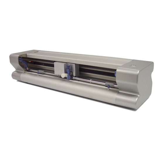
This user manual contains numerous links to videos, such as the one just above which presents an overview of
the Zing cutter. Click on these green Video icons to open either a You Tube or Vimeo hosted video and learn
the topic in that particular section of the manual. Past experience has shown that watching videos can be
extremely beneficial when learning software and cutting applications.
Bookmarks
Click on the Bookmarks icon to list the major chapters of the manual and then click on a chapter to immediately
go to the first page of that chapter. You can also enter a page number at the top in order to go to that specific
page.
Searching
You can search by any word at all. Click on the Search icon, enter any word, and all pages with that word will
be listed. Select any page and the word will be highlighted in yellow.
Downloading
You may download this manual, if you wish, in either PDF format or as an application that will continue to work
in the same way that it does online. But again, this is a manual that will be updated, as needed.
Printing
Do NOT print this entire manual!!! It will be changing as enhancements are made to Make-The-Cut or new
applications are added for using your Zing. Thus it's better to print only those pages you might need for a certain
topic, at a specific moment. And you may never need to print any of it at all.
Where to Start
Thank you for choosing a KNK Zing. Before using a blade in your new cutter, we suggest you read the
Quick Start Guide that came in your Zing box plus Chapters 1 and 2.
If you run into difficulties with the operation of the Zing, turn off the power and look for a solution in this
manual. If you continue to have technical questions or issues, please contact your KNK Zing supplier as
soon as possible.
For additional support, please visit our Yahoo group at:
1
© 2011, 2012 Accugraphic Sales, Inc., All Rights Reserved
KNK Zing with Make-The-Cut
April 20, 2012
1
http://groups.yahoo.com/group/KNK_Zing/
1
Advertisement
Table of Contents

Related Manuals for KNK Zing

Summary of Contents for KNK Zing
- Page 1 If you run into difficulties with the operation of the Zing, turn off the power and look for a solution in this manual. If you continue to have technical questions or issues, please contact your KNK Zing supplier as soon as possible.
-
Page 2: Table Of Contents
Front ............................................8 Back ............................................8 1.05 A ....................................9 CCESSORIES Test Pen Holder ......................................... 9 Blades Included With KNK Zing Purchase ................................9 Blade Installation ........................................9 Mat (Carrier Sheet) ........................................10 1.06 I (MTC) S ..............11 NSTALLATION OF... - Page 3 EPS/AI, SVG, PDF ............................. 64 XPORTING AS 4.13 E ................................64 XPORTING AS A ASTER 4.14 U ................................. 65 SING INDOWS ASTE Adobe Illustrator ........................................65 Inkscape ........................................... 65 KNK Studio/ ACS Studio......................................65 5. WORKING WITH TEXT ..................................67...
- Page 4 5.01 T ................................67 EXT AND ONTS 5.02 O ..................................67 PENING ILES 5.03 A .................................... 68 ROUP Rotating Text ........................................... 69 Splitting Text ..........................................69 5.04 C ............................70 REATING A ONNECTED ETTER ITLE 5.05 I ..........................71 NCORPORATING INGBAT HAPES INTO A ITLE...
- Page 5 Drawing Curves ........................................124 Combining Straight Lines and Curves ................................125 7.13 E ) ..........................125 ATHS AT EVEL Segment Editing ........................................125 Node Editing .......................................... 128 Applications for Node Edit ....................................129 8. DESIGNING ......................................130 8.01 W ? ..........................130 HERE TART WITH EARNING TO...
- Page 6 Extra tips on Rhinestone Applications ................................172 10.07 D ............................. 172 RAWING WITH A EN OR Adjusting for the Difference in Diameters of Tools and Blade Holders ......................173 10.08 E ................................175 MBOSSING AND CORING 10.09 E ..................................176 NGRAVING ETAL Project: Engraving a Dog Tag ....................................
-
Page 7: Unpacking, Installing, And Assembling
Do not unplug the USB cable from your computer or from the KNK unless you first turn off the power. Always turn off the Zing when not in use. Leaving the cutter turned on for extended periods of time can possibly damage the machine. -
Page 8: Parts Of The Zing
DO NOT touch the cutter with a magnet. DO NOT allow small items to fall into the cutter. TURN OFF the cutter when not in use. 1.04 Parts of the Zing Front Press Ring: Blade Carriage Limit Switch:... -
Page 9: Accessories
The test pen should be used until you are comfortable with the operation of the KNK Zing and know, with certainty, where shapes will cut. To assemble the test pen, remove the top cap, slip the spring over the top half of the pen insert and then drop the pen insert into the bottom half of the pen holder. -
Page 10: Mat (Carrier Sheet)
But if not, apply a repositionable adhesive as necessary. IMPORTANT: Do not spray adhesives around your KNK! Not only can the adhesive get stuck to important parts of your Zing, but these adhesives should only be used in well-ventilated areas. Breathing in the adhesive can be damaging to your health! ... -
Page 11: Installation Of Make The Cut (Mtc) Software, Zing Driver, And The Zing Plug-In
Close all programs not needed and insert the MTC CD into a CD Rom on your computer. Even if you already have MTC installed, you will want to reinstall in order to add the Zing plug-in and the Zing driver to your computer. -
Page 12: Mat/Material Guides
If the blade carriage is preventing easy access to the guides, then turn off the Zing. Now you can manually slide the blade carriage to the left so that you can more comfortably access these guides. - Page 13 In Landscape mode, the arrow on the virtual mat will point to the left. When you draw or cut out the “ABC” shown on the Landscape Virtual Mat, it will be drawn or cut top to bottom as you face the Zing:...
-
Page 14: Drawing Your First Shape
2. Insert the mat into the cutter, with the mat snug between the material guides. Slide the mat towards the back and use any of the horizontal markings at the front of the Zing to align the mat. Then lift the pinch levers to drop the pinch wheels onto the cutting mat. - Page 15 Select your preferred mode: Landscape or Portrait 5. Before adding a shape to draw, double click in the gridded area on the screen to plant the Caret. This will determine where the shape will be imported: Double click to plant the Caret (the vertical red line) onto the virtual mat.
- Page 16 9. If, instead of seeing “Connected (COM X)”, you see “Not Connected”, then your computer is not identifying the Zing. Do the following: Turn off your Zing. Unplug and reconnect the USB cable at both the Zing and the computer to make sure the cable is firmly plugged in. ...
- Page 17 Feed the mat this direction into the Zing Move the pen tip Move pen tip to to this corner of this corner of the the paper. paper. 12. Click on Cut Project and your arrow shape will be drawn at the new origin you set. After the cut is complete, the cut window will close.
-
Page 18: Cutting
The key to becoming successful at cutting is to do a lot of it! Those who shy away from using their Zing will never get to the stage of mastering it. It’s very normal for new owners to be intimidated by their cutter, so remember the following key things: ... -
Page 19: Use The Correct Blade For The Material You Are Cutting
If you do see cut lines in your mat, retract the blade length by turning the top of the blade holder ~¼ of a turn counterclockwise. You do not need to remove the blade holder from the Zing. Repeat your test cut. Material... -
Page 20: Adjust The Speed, Force, And Number Of Passes Based On The Material And Shapes
One recommended method for getting the same height set for all of your cuts is to use three old credit cards. Set the three cards in a stack on top of the material you plan to cut. With the Zing turned off you can move the blade carriage to the left until it is over the cards. -
Page 21: Keep The Cutting Mat Clean And Sticky
Before accessing the Zing cutting window, you need to have at least one shape on the current page to cut. If you have no shapes, then attempting to access the cutting window will result in a popup message stating, “There is nothing inside the current project to cut!”... -
Page 22: Speed
Alternatively, left click on the dial once and then use the up and down arrows on your keyboard to change the setting. The movement within the Zing logo can be toggled on and off by left clicking on the logo. 2.03 Speed ... -
Page 23: Force
The Cut Speed is the speed of the blade (or other installed tool) while it is in the “down” or cutting position. The Zing has 20 speed settings, with 8 of them being below 100mm/sec. This cutter was designed to handle a wide range of thicker, more difficult materials that will cut far more successfully with a slower cut. -
Page 24: Multicut
˚ capped blade and a Blade Offset of 0.75 for the included blue capped 60 blade. The Zing fabric blade should also use an offset of 0.75. If you use other brands of blade holders, you may need to experiment with the Blade Offset setting. -
Page 25: Cut Type
2.07 Cut Type There are three modes in controlling where images will cut to the Zing. They are called: Knife Point: Moves the shapes to cut at the origin. Use the blade tip to set the origin for cutting. -
Page 26: Wysiwyg
Place several scraps (large enough for the shapes on your screen) on your mat in different locations, as shown below. Insert the mat into the Zing and then set the origin at the lower right corner of one of the scraps and cut the currently selected shape. ... -
Page 27: Wysiwyg - Virtual Mat Matches Ruled Grid On Actual Mat
Create the typical mat that is sized 12” x 12” and uncheck the option to Show Margins. This will be a mat that matches the ruled dimensions of the Zing mat. You can use either Portrait or Landscape mode - just remember to place your material on the mat in the correct orientation for feeding into the Zing. -
Page 28: Wysiwyg - Virtual Mat Matches Material Dimensions
(see below). Note that if you need absolute precision for the location of your cuts, it will be necessary to calibrate the Laser Offset, which is covered in Chapter 9. WYWIWGY – Landscape Mode Feed the mat this direction into the Zing Indicates Landscape mode Origin is set here using the... -
Page 29: Print And Cut
Click on the green arrows to move the carriage left and right and the mat in and out of the Zing until the blade carriage is in the location you wish to use. IMPORTANT: At the current time of this writing, there is a software bug which will be invoked if you use the Up arrow (either in the software or on your keyboard) to move the mat more than 1”... -
Page 30: Connection Status And Test Cut Menu
The laser can be turned on or off in this menu by choosing Toggle Laser On. Or, any time you are in the Cut with Klic-N-Kut Zing window, you can press F2 to toggle the laser. The laser will also be turned on when going to the Set Blade Origin window. -
Page 31: Important Checklist Before You Cut
2.11 Important Checklist Before You Cut! Do you have your material on the mat and the mat inserted into the Zing? (Note: materials with a backing sheet, such as vinyl and iron-on transfer do not require a mat for cutting) -
Page 32: Resolution Calibration
Slide the mat out but leave the paper on the mat. Note that regardless of having your Virtual Mat set to Landscape or Portrait, the Width of the square is the left-to-right dimension as you face the Zing. The Height of the square is the front to back dimension:... - Page 33 Because the Zings are so very close to being perfectly accurate, only take note if the sides are slightly larger than 10” or slightly smaller than 10” because it will probably be so close that you cannot even measure the distance from 10”...
-
Page 34: Suggested Settings For Various Materials 1
Suggested Settings for Various Materials Speed Blade Material Type Material Brand or Source Blade Force Other Comments (Cut/Up) Offset Passes Acetate Grafix - 0.005" 10 / 10 0.35 Doesn't handle very thin Balsa 1.5 mm from Michael's Blue 8 / 11 parts: use light Can vary greatly based Cardstock... - Page 35 Speed Blade Material Type Material Brand or Source Blade Force Other Comments (Cut/Up) Offset Passes Lutradur - Light Wt ctpub.com 10 / 10 0.35 Magnet - Printable 20 mil Blue 9 / 10 0.75 Mylar - 0.005" Tapplastics.com 10 / 10 0.35 Paper - Set blade to minimal...
-
Page 36: Settings Form For Cutting Materials
Settings Form for Cutting Materials Material Brand or Speed Blade Material Type Blade Force Other Comments Source (Cut/Up) Offset Passes... -
Page 37: Mtc Basics
3. MTC Basics This chapter begins the Make-The-Cut User Manual. As noted on the first page, this is meant to be an online interactive manual. Refer back to that page for features to use while reading online. It is highly recommended that you do not print this entire manual. -
Page 38: Toolbars
Hovering your mouse over any of the screen icons will pop up the icon’s name and/or function and shortcut key. Identification of these icons is also presented in Sections 3.02, 3.03, and 7.06. Most of the bars and toolbars may be moved to different locations on the screen. Hold down the left mouse button on the gray dots along the left side of the bar or toolbar and drag. -
Page 39: Magic Toolbar
Magic Toolbar The Magic Toolbar contains the functions that are used in editing and designing: Select All: Flip: Split: Break Join: Boolean Join: Conical Warp Lattice Advanced 7.02 – 7.05 5.08, 7.01 5.08 8.06 3.09 3.15 5.04, 7.01 7.01 8.07 Mirror: Rotate 90... -
Page 40: Main Bar
Main Bar The Main Bar has two tabs: Virtual Mat and Text and Fonts. The Virtual Mat tab allows you to set the size and visual appearance of the mat, as well as orientation, the appearance of shapes, snapping to grid, and Caret size. -
Page 41: Status Bar
Right click on any Page name on the Page Bar and a menu of options will appear: Move current page forward or backward along Page Bar Rename current page Duplicate current page – see below Options to Cut, Copy, and Paste pages to a different location on the Page Bar Paste all shapes from Cut page into... -
Page 42: Zooming And Panning
For the Zing and other KNK cutters, having a margin isn’t necessary, thus the Margin options can be left unchecked. For cutters that have areas of the mat that cannot be used, then enter the necessary margins. -
Page 43: Opening Mtc Files
5 – 0: Zoom to 500%, 600%, etc to 1000% To move the workspace up and down, roll the mouse wheel. To pan, press the Spacebar while dragging the left mouse button. 3.06 Opening MTC Files Opening a New File/Project ... -
Page 44: Saving Mtc Files
This project has been saved using the name shown but the asterisk indicates This project has been saved This is a new project that that changes have been made since the hasn’t yet been saved. using the name shown. file was last saved. ... -
Page 45: Selecting, Moving, And Deleting Shapes
Go to File>Import>From Basic Shapes You may then select one of the predefined categories and all shapes within that category will be displayed. Double click on a shape to import it directly onto the screen at the same height and same location as the Caret. -
Page 46: Moving
Right click on the screen and choose Next Shape (or choose Previous Shape) Press Shift+Tab (or press Shift+Esc) Go to Edit>Next Shape (or go to Edit>Previous Shape). To unselect all shapes, use one of the following two ways: ... -
Page 47: Cutting, Copying, Pasting, Duplicating
Press Shift+Delete Go to Edit>Delete All. You can also delete a layer of shapes at one time from the Layer Bar. Refer to Section 3.12. To delete all of the tiny shapes not wanted in your project, use any of the following to access the Delete by Area option: ... -
Page 48: Duplicating
To Paste shapes from the clipboard, use any of the following: Click on the Paste from Clipboard icon located on the File Toolbar Right click on the screen and select Paste Press Ctrl+V Go to Edit>Paste. ... -
Page 49: Redo
Press Ctrl-Z Go to Edit>Undo. If you are experiencing software crashes due to memory limitations, one solution is to limit the number of Undo steps stored in memory. To do this, go to Help>Advanced>Limit Undo Size: Enter the maximum number Click on Set of Undo steps stored (or 0 for unlimited) - Page 50 Layer Options Menu at the bottom of the Layer Bar. Individual shapes are also assigned to their own layers within a layer, as shown in the screenshot on the following page. The words “KNK” and “Zing” are individual layers within the layer which displays both words together. ...
-
Page 51: Resizing, Rotating, Slanting, And Warping
3.13 Resizing, Rotating, Slanting, and Warping The Resizing, Rotating, Slanting and Warping functions are presented together because all four are readily invoked on any selected shape. When you first select a shape, you will notice that the bounding box has double headed arrows at the four corners and in the center along each of the four sides. -
Page 52: Rotating And Slanting
Fractions may also be entered with a space between the number and the fraction. For example, 6.5 could be entered as 6 ½: Enter 6 ½ (don’t The H value remains at 1.0 A value of 6.5 is Starting Size because the Aspect Ratio forget the space). -
Page 53: Changing Color, Texture, And Line Style
Note: throughout this user manual, screen shots of shapes will sometimes appear without the gridlines of the virtual mat in the background and without the bounding boxes around the shape(s). This was done to make the images appear clearer and less cluttered. 3.14 Changing Color, Texture, and Line Style ... - Page 54 After importing this first texture, or if there was already a texture open in your current project, then the Choose Texture window opens. In this window, you have options to: Tile the Texture (fill a shape with a modified version of the texture) ...
-
Page 55: Changing Line Style
Click on Adjust Color option to open this Preview of how window and changes to change the color settings are settings, as customizing the desired texture Option to Flip Vertically marked and image rotated 45 degrees, scaled to 18%, and color adjusted. ... -
Page 56: Other Shape Manipulations
3.15 Other Shape Manipulations Aligning There are seven alignment functions used to align shapes with one another. After selecting two or more shapes, these functions can be accessed using any of the following: Right click on the screen and select Align and Space>Align> ... - Page 57 Press Ctrl+M Go to Edit>Shape Magic>Mirror. To vertically flip a shape, select it and then use one of the following:: Click on the Flip icon on the Magic Toolbar Right click on the screen and select Shape Magic>Flip ...
-
Page 58: Importing And Exporting
4. Importing and Exporting 4.01 Accessing the Import Options Go to File>Import and select from one of the available import options. Note the shortcut keys for the various file types: For all raster shapes Opens LD’s web site with access to user’s account and ability to import free Freely shared files from and purchased files... -
Page 59: Importing Svg, Svgz From Your Computer
Each thumbnail MTC uploaded files indicates the File appear with a Virtual Mat Name, Category, background. Description, User ID, and Uploaded Date. SVG uploaded files appear without the Virtual Mat background. If just the shape was uploaded, then clicking on Download will immediately import the shape at the current location of the Caret. -
Page 60: Importing Ai, Eps, Ps, Pdf
SVG was created, you need to know which program was used. For example, if the SVG file was created in Inkscape, use 90 DPI. If the SVG file was created in either Adobe Illustrator or KNK Studio, use 72 DPI. While knowing this setting isn’t relevant in most files, such as the one shown above, there could be some files where it is very important, such as an envelope template for a certain sized card or a cupcake wrapper template. -
Page 61: Importing Scut, Scut2
MTC will only import AI files that are Version 9 or newer. Thus, if an AI fails to import, that is the most likely issue. From some programs, such as Funtime, it will be necessary to save in a different format, such as PDF or EPS. -
Page 62: Importing Raster Files (Jpg, Bmp, Png, Etc)
The following example shows a collection of clipart called “Arizona Grand Canyon State” that has been found at the Lettering Delights site, but has not yet been purchased. You can see the images contained in this collection and, upon double clicking any of the images, a window will open: ... -
Page 63: Exporting To Basic Shapes
Exports selected shape to the “Your Shapes” category under Basic Shapes. Allows user to upload selected shape to the online MTC Gallery Export in one of the common vector standard formats Export shape as a raster file 4.10 Exporting to Basic Shapes ... -
Page 64: Exporting As Eps/Ai, Svg, Or Pdf
4.12 Exporting as EPS/AI, SVG, or PDF For each of these formats, first select the shape or shapes and then select the Export option from the dropdown menu (right click on selected image for Export option). A window will open: Select location for saving file Select... -
Page 65: Using Windows Copy/Paste
KNK Studio/ ACS Studio In KNK or ACS Studio, select the shape or shapes and use Ctrl+C or Edit>Copy to copy the images to the Windows Clipboard. In MTC, use Paste in Place (Ctrl+Shift+V or the icon on the File Toolbar ) to import the KNK shapes at the original size. - Page 66 MTC. If any of the VEF and WFN fonts specific to KNK/ACS Studio have been used to create text, that text may also be copied and pasted from KNK/ACS Studio to MTC even though those particular fonts cannot be opened in MTC.
-
Page 67: Working With Text
5. Working with Text 5.01 The Text and Fonts Tab On the Main Bar in MTC, you will find a tab called Text and Fonts: Click on this tab to access Text and Fonts The Text and Fonts tab is used for: ... -
Page 68: Add Text Group
installed in Windows in order to be used. They can be opened directly in MTC, as easily as importing other vector files. A font can be opened in MTC using any of the following ways: Click on the Import TTF/OTF icon on the Import Toolbar: ... -
Page 69: Rotating Text
As you type the text, it will also appear on the screen at the location and height of the Caret (refer to Section 4.01). After clicking on Accept in the above window, the Add Text Group closes and the text is ready for any additional editing desired: Rotating Text ... -
Page 70: Creating A Connected Letter Title
Split by Spaces: Spaces created using the space bar will divide text into separate shapes: 6 shapes, one for each word Split by Glyphs: Each typed character will be its own individual shape: 19 shapes, one for each character- characters can be individually moved, as desired ... -
Page 71: Incorporating Dingbat Shapes Into A Title
Go to Edit>Shape Magic>Split. With the letters split, you can select one or more and use the left and right arrow keys to change the spacing between letters, overlapping as desired. It is advisable to zoom in on the text to get a more accurate view of the actual positioning of the letters. -
Page 72: Welding Titles In Imaginative Ways
Select font Double click the image you want and it will be inserted at the location of the Caret. Scroll to make images larger, if desired Some dingbat fonts will show up, as images, in the dropdown list of all fonts. Thus, uncheck Show Face, as needed. ... -
Page 73: Fitting Text To The Outside Of A Shape
5.07 Fitting Text to the Outside of a Shape Wrapping Text Around A Circle The Wrap Objects To Path function can be used to fit text to the outside of a shape. In this example the words “Happy Birthday” will be wrapped around a circle three times. ... -
Page 74: Wrapping Text Half-Way Around The Top And The Bottom Of A Circle
Vert. Align: This indicates how close the original text is positioned to the circle. At 100%, the text just touches the circle but the setting can be increased to move the text outwards, away from the center of the circle or decreased to move the text inwards, towards the center. ... - Page 75 Text is now spaced and positioned along top half of circle. Adjust settings and write down the Vert. Align and Space settings. Click on Accept when done. After clicking on Accept, the second half of the text is selected and, again, moved to the center of the circle while holding the Ctrl key: Second half of text shows up with...
-
Page 76: Fitting Text To Paths
The Wrap Object to Path can be used for other designing applications, one of which is shown in Section 8.05. 5.08 Fitting Text to Paths A different function, the Bézier Warp, can also be used to fit text to a circle or to fit text to a custom designed path. -
Page 77: Open Path In Bézier Warp
Open Path in Bézier Warp To use an open path, the Close Curve option is unchecked, so that the path is a line instead of a circle. Next, more Points are added and then the points are dragged to create the desired path. Use the Zoom setting if you cannot see your entire text. - Page 78 It will also be easier to select individual letters if the rectangle is on its own layer and below the text. With only the rectangle selected, click on the Selection to New Layer icon (at the bottom of the Layers Bar) and then move the rectangle layer so that it is below the text layer: The selected rectangle is moved to Then, the layer with the rectangle...
-
Page 79: Stenciling Letters
Go to Edit>Shape Magic>Boolean Join. The following popup menu will appear and as you move your mouse over the various options, you will see your image change on the screen. The option called B-A Difference shows the rectangle outline disappearing where the letters overlap, which is what you want in this case: Click on drop down menu to select one of the five choices. -
Page 80: Open Path Fonts (Opf)
Overlap rectangles wherever you want openings to be created. Click on the thumbnail of the rectangles layer on the Layers bar and then apply a Join (Ctrl+J) so that the rectangles are now a single shape. Marquee-select the text and the rectangles and use Ctrl+U to bring up the Boolean Join menu. Choose the same option that was used in the previous section: B-A Difference: ... -
Page 81: Tracing
6. Tracing 6.01 Raster Versus Vector All graphics are either raster or vector and there is no third type. While you can often tell by the file format, even that isn’t always a good way to know for certain. For example, a PDF file can be made from either raster images or vector images and some PDF’s will contain both types. -
Page 82: Finding Easy Images To Trace
6.02 Finding Easy Images To Trace What qualifies as an easy image? The obvious answer is “an image which gives you the results you want!” But those who are new to the vectorizing process do not always realize which images are going to be easy and which ones are not. -
Page 83: Pixel Trace Method
The image will open in the Pixel Trace window. Note the following information in this window: Visualization Settings: adjust for personal preference only. These settings do not affect the trace. results. On-screen Preview will appear at current location of the Caret Trace options and settings (covered... - Page 84 Image in Pixel Trace window: Resulting trace after import Threshold: 1 Threshold: 75 Threshold: 127 Threshold: 250 Threshold: 255 Lots of detail Losing wing detail Wings missing Detail in claws missing Border only traced As shown in the above example, the most detail was obtained with the lowest Threshold. Typically, this is not necessarily what you want in your tracing.
- Page 85 The Background Color setting becomes usable when there is a transparent or alpha channel in the image you are tracing (such as you will find in some PNG and GIF files). The background color will define the semitransparent pixels by blending them with the background color you select. Here is a photo of a white car that illustrates this feature: ...
-
Page 86: Alpha Trace Method
This can be used to identify and trace different parts of an image, however, with the newer Alpha, Palette, and Color options available, this feature may not ever be something you need. Alpha Trace Method Use the Alpha Trace for PNG files with transparent backgrounds (alpha channels). To switch to the Alpha Trace method, click on the tab named Alpha and following will appear: Resample Image and Despeck will be used... - Page 87 outline around the image. Additionally, either a Despeck of 18 or marking Blackout Path was needed to remove tiny paths traced inside the animal: Threshold is increased to 240 Blackout Path is marked to remove tiny interior paths. However, if you switch to the Alpha Trace tab, the default of 127 immediately gives you, in this case, the outline you want: Alpha Threshold default value of...
-
Page 88: Palette Trace
Palette Trace The Palette Trace provides color tracing which is especially useful when designing paper piecing patterns. In this example, the following flower image was imported and will be vectorized: With the Palette Trace, the most prevalent 16 colors in the image are identified and displayed. To switch to the Palette Trace method, click on the tab named Palette and the following will appear: Resample Image and Despeck will... - Page 89 Click once on each pink box to mark it. If you inadvertently click on a color box you do not with to include, click again to deselect it. Use Despeck to eliminate tiny unwanted paths and Resample Image to sharpen details or provide more curves to the image.
- Page 90 The flower center is now added to the tracing Mark the dark purple color and then click on Apply Changes. Click on Import and the program will ask you if you want to continue tracing and add more layers. Answer Yes.
- Page 91 One of the petals still appears! Mark the Blackout Path option and then click on Apply Changes. There is one small spot where the black is not a continuous path. But there’s a problem! Instead of seeing one large black outline of the flower, there’s still a petal showing. This is because the black wasn’t recognized as extending around the outside edge of that petal.
- Page 92 While individual layers can be selected, you cannot individually turn the layers on and off for cutting by colors. Thus click on Layer Options Menu and select To Each Its Own. Now each of the four colors has been moved to its own higher level layer where you will now be able to turn on and off individual layers for cutting.
-
Page 93: Color Trace
Color Trace The Color Trace is similar to the Palette Trace but you can individually click on a color, from your original imported raster, to trace and then specify a Tolerance level which will add or subtract similar colors to include in that selection. - Page 94 Despeck raised to remove tiny paths. Blue lines and green fill indicate portion of The Color box image traced. changes to the color selected with the eyedropper. Click on Apply Changes each time a change is made to update the preview. Preview on screen ...
- Page 95 Tolerance is still set to The leaves and stem are both traced. If you want the leaves and stem to be traced as different shapes, then reduce the Tolerance. It was required to reduce the Tolerance all the way down to 2 in order to get just the leaves traced: Tolerance is reduced to 2.
- Page 96 Tolerance kept low. Stems are now traced. Click on Import and now repeat for the blue and pink flowers. It is decided that just the main parts of the flowers will be traced and not the darker borders around the flowers. Shadow layers can be created later, if desired.
- Page 97 Increase Tolerance to 5. The inner circles where the color is a very pale yellow are not included. Increasing the Tolerance gradually reduces the sizes of those inner circles: Increase Tolerance to 40. However, there’s an easier way to handle those! Just mark the Blackout Path box and they are instantly removed from the trace:...
- Page 98 Click on Blackout Path Click on Import and, this time, answer No. The tracing part is complete Now for the editing. Select the tracing click on the Layer Options Menu icon and select To Each Its Own. Now the image can be edited, as needed and the colors turned on or off for cutting. After selecting To Each Its Own from the Layer Options Menu, each...
-
Page 99: Manual Tracing
Click on the layer preview Apply a Ctrl+B (Break) so that the pink flower border that was traced with the flower pot can now be selected and deleted. Then the flower is ready to cut from individual colors of paper, cardstock, vinyl, etc: 6.04 Manual Tracing ... - Page 100 Set Threshold to the maximum of 255. Mark Texturize Path box. Mark Texturize Path box Click on Apply Changes. Click on Import. Click on Import. Answer No when asked if you wish to trace more layers. The image will appear on the screen.
-
Page 101: Manual Tracing Using The Bézier Curves And Straight Line (Pen Tool)
The image will now be slightly grayed, but still distinct enough for tracing. Manual Tracing Using the Bézier Curves and Straight Line (Pen Tool) As mentioned at the beginning of this section, you will want to read Section 7.12 to learn how to comfortably and successfully use Pen Tool. - Page 102 When you reach the original starting point and right click on it, the shape will fill with color and you will have a closed path, in spite of starting and stopping along the way. Now to show this process in more detail: ...
-
Page 103: Flip/Mirror And Weld To Complete Symmetrical Shapes
Start and end another curve segment to finish bottom curve of dress. Then do another short straight segment along bottom, followed by a long segment up center of dress:: 11. Left click on top of last 12. Hold down left mouse 13. -
Page 104: Editing
7. Editing 7.01 Separating and Combining Shapes Split The Split function is used to break up combined shapes into individual shapes, but keep inner paths joined to their respective outer paths. Sometimes the outer paths are called parent shapes and the inner paths are called child shapes. -
Page 105: Break
Bounding boxes now indicate a total of 8 different shapes. Break The Break function is used to separate every path, every curve, and every line into its own individual shape. After selecting a combined shape, the Break function can be accessed in any of the following ways: ... -
Page 106: Layer
The grid is visible again inside One single bounding box the inner parts of the letters. around the entire word Another reason to apply Join before cutting is to control the order of the cutting. A child shape, which is joined to a parent shape, will always be cut before the parent. -
Page 107: Blackout
The three parent paths are three shapes The two child paths of “o” The two child paths of the letter and “b” are the final two “B” are now one single shape shapes. Blackout The Blackout function deletes all child paths from their parent paths. ... -
Page 108: Shape Magic Advance Part 1: The Simplify Functions
7.02 Shape Magic Advance Part 1: The Simplify Functions Auto Simplify Welds The Auto Simplify Welds function is an on/off feature which should be turned on when MTC is installed. Its purpose is to continuously reduce the number of nodes after other functions are applied, so that a design will cut smoothly and quickly to a cutter. -
Page 109: Shape Magic Advance Part 2: Details
Go to Edit>Shape Magic>Advanced>Smooth & Simplify. The following window opens with settings which can be adjusted as desired. Adjustments will be reflected in the preview so that distortions of the image can be avoided: Option to show nodes Adjust these settings and note Preview of... -
Page 110: Nodes On Mat
Numbers of Shapes, Segments, This is a step-by- Points, and step list of paths Nodes which make up the selected shapes. It Preview of forms a roadmap of image how the blade will travel when cutting. Nodes on Mat The Nodes on Mat function is an on/off feature which will be turned off when MTC is first installed. -
Page 111: Thin Paths
If you are trying to align the top, left, or right sides of this heart with another shape or shapes. Because of the gaps, you wouldn’t be able to use the alignment functions from Section 3.15, with the exception of the bottom alignment. -
Page 112: Fuse N' Weld
Fuse n’ Weld The Fuse n’ Weld function is used to remove duplicate shapes in the same path and also join nodes together that are on top of one another. This is mostly commonly used when importing certain file formats in which there can be hundreds of small disconnect paths making up the shape. -
Page 113: Shape Magic Advance Part 4: Tiler
Reverse Paths can be accessed in any of the following ways: Click on the Advance icon on the Magic Toolbar and select Reverse Paths Right click on the screen and choose Shape Magic>Advanced>Reverse Paths from the menu ... - Page 114 Only the Tile Width must be set to something less than 15” since the Zing can handle 14” wide cutting. For this example, the Tile Width will be set to 13.5”. The Zing can also cut long sections of vinyl at one time, so the Tile Height will be set slightly larger than the height of the shape.
-
Page 115: Node Mode Toolbar
The individual tiles are placed on new Pages on the Page Bar: Original shape will still Four new pages are created to house the four tiles be on original page 7.06 Node Mode Toolbar The Node Mode Toolbar offers tools to use for editing shapes, drawing lines and curves, importing from the Basic Shapes library, and a number of other functions. -
Page 116: Measure Shape Lengths And Angles (Measure Tool)
Holding the Ctrl key while dragging to create the shape will release the Aspect Ratio, allowing you to make the shape thinner or wider relative to the height, as you desire. You may need to adjust Snap Position on the Virtual Mat tab: With Ctrl key held, …... -
Page 117: Slice Shapes And Lines (Knife Tool)
Likewise, when you hover the cursor over an outer side of the other star, the solid area of the star will fill with stripes and the properties of the outer star will be displayed. If you hover the cursor over the inner star, then the properties of that star will be displayed instead: Properties of Properties of... -
Page 118: Draw Freehand Lines
The Knife Tool will be used to remove the bottom line of this shape. To slice off just the bottom of the shape, select the Knife Tool and hold down the mouse button outside of the shape on one side, just barely above the bottom of the shape and then drag the mouse over to the other side, letting go once the cursor is outside of the shape: Drag the mouse to the other Begin cutting just... -
Page 119: Drawing Thick Lines
Precision: 0% Precision: 100% Precision: 50% If you need to draw a perfectly straight line, hold the Ctrl key while drawing: The Force Closed Path option can be marked so that, as you draw an image, the start and end will always be connected. -
Page 120: Erase Sections Of Paths (Eraser Tool)
Note that the Line Cap style option also works in combination with the Dash Style options to produce even more options: 3 different Line Caps Flat Round Triangle 5 different Dash Styles 7.11 Erase Sections of Paths (Eraser Tool) Erasing ... -
Page 121: Inverse Erasing (Adding To An Image)
Enter the Size (thickness) of eraser you want to use. Leave unchecked Hold down the left mouse button and drag the mouse in a small line where you want to erase. A red line will be drawn and, when you release the mouse button, the portion of the shape beneath that red line will be erased: Shape needs to be erased Drag mouse along path to be... - Page 122 Back to our prior example, the gray path around that last yellow petal represents the black shadow layer that was hidden during the erasing process. Notice how it becomes very thin in that area where the last petal was smoothed: Shadow layer is very thin at this point.
-
Page 123: Eraser Or Knife
Eraser or Knife? In Section 7.09, it was shown how the Knife Tool can be used to cut shapes into parts. The Eraser Tool can also be used for this same purpose when the Size is set to a very small value, such as 0.03 mm (the minimum size allowed). -
Page 124: Drawing Curves
Left click once Move cursor to where you want Right click to end drawing of the line. to begin. to finish the line. If you wish to continue drawing a connecting straight line path, then instead of right clicking to end, keep left clicking. -
Page 125: Combining Straight Lines And Curves
Combining Straight Lines and Curves There are different methods for creating a continuous string of straight lines and curves. The straight lines are easy because, as you left click to plant nodes, the straight lines remain straight and do not change as you create the next connected straight line. - Page 126 Hovering over a Selecting a segment Selecting a segment, with a green segment turns it red turns it green mat, turns the segment blue A selected segment can now be “dragged” in the following ways: Drag on the segment with your mouse to change the curvature in different ways: Drag a segment in any direction to transform into Upon releasing mouse button, different shapes.
- Page 127 Insert Mid-Point Node: a node will be inserted exactly half-way along the selected segment and the segment is now split into two segments of equal length. Place cursor anywhere Segment is split into two along segment segments at the midpoint. ...
-
Page 128: Node Editing
Node Editing If you hover your mouse over one of the end nodes on a selected path, you will see it become encircled with a dotted red path. That means the node can now be edited. For example, you can drag the node to a new location and the connecting segment(s) will move as well. -
Page 129: Applications For Node Edit
Delete Node: The node will be deleted and the two segments will become a single segment. The Bézier control points of the new segment will automatically adjust to try to recreate the previous path of the two segments: Break Node: Breaks the node into two nodes so that the segments are no longer connected. -
Page 130: Designing
8. Designing 8.01 Where Do I Start with Learning to Design? MTC offers some excellent easy-to-use designing tools to assist you in creating whatever you can imagine! The best way to learn these tools is to focus on only one at a time, watch the related video, and pause the video after each step, to repeat what you are seeing. -
Page 131: Blackout Option
Blackout Option The Blackout Option can be toggled on and off to either apply the shadow to interior paths or to black out the shadow and only have a single outset: Blackout applied Blackout not applied Corner Join Option The Corner Join controls the style or shape of the shadow at the corners. -
Page 132: Weld Tool
8.03 Weld Tool The Weld tool removes the overlap between two or more selected shapes. After selecting the shapes, it can be applied in any of the following ways: Click on the Weld icon on the Magic Toolbar. ... -
Page 133: Boolean Join
8.04 Boolean Join The Boolean Join menu contains five welding options but it can only be applied to two selected shapes at one time. If you have more than two shapes, then just apply the Boolean Join to any two at a time or, in most cases, you can either use the Weld (Ctrl+W) function or the Join (Ctrl+J) tool first to reduce your multiple shapes down to two and then use the Boolean Join function needed to complete your design. -
Page 134: Wrap Object To Path
Two bounding boxes, The text forms one shape. The two thus two shapes hearts are now the second shape Marquee-select the two shapes and go to the Boolean Join menu (Ctrl+U). Select the second option: B-A Difference. Note that if the hearts had been behind the title (positioned in a lower layer than the title), then the A-B Difference would have given the desired result. -
Page 135: Conical Warp
In order to get equal spacing and for the images to overlap for welding, begin tweaking the Vert. Align and the Space settings. The Space setting is actually changing the Spacing setting you originally entered by some percentage so that you can visually achieve equal spacing of the repeats around the circle. If the spacing entered were positive, then a larger Space value will, logically, increase the spacing between the objects. -
Page 136: Tumbler Wrap
Press Ctrl+Q Right click on the screen and select Shape Magic>Conical Warp Go to Edit> Shape Magic>Conical Warp Tumbler Wrap A design has been created for the wrap. The pumpkin is from the free Create-A-Card set in the Lettering Delights window. -
Page 137: Lattice
This feature can also be used in the design of cupcake wrappers! 8.07 Lattice The Lattice feature can be used to create a lattice design within a shape or part of the entire shape itself. It can be accessed in any of the following ways: ... -
Page 138: Rhinestone Design
Now the design shown would cut exactly as shown. You would have a single cut piece. But for some lattice designs, the opposite is wanted. For example, when cutting a design from the front of a greeting card, you plan to keep the card and not the design itself. -
Page 139: Rhinestone Fill
the letters so that the circles will not overlap. Also, you may want to resize the lettering vertically to make the letters taller. This allows more circles to be applied and can improve the ability to read the text: Letter is still 6” wide but is now 3.6”... -
Page 140: Additional Tips On Rhinestone Designing
Additional Tips on Rhinestone Designing Sometimes the circles you want to respace equally may fall closer to a 45 angle versus vertically or horizontally. Select your entire design and rotate until the line of circles are closer to vertical or horizontal. Respace using the [ or ] shortcut keys and then rotate back into place. -
Page 141: Jigsaw Puzzle
8.09 Jigsaw Puzzle The Jigsaw Puzzle feature installs as a separate application. To open it, go to your Windows Start button, select All Programs, locate your Make The Cut! folder and then select Jigsaw Puzzle Generator. The following window will open: Enter desired Width and Height (which can be changed after importing into MTC). -
Page 142: Notes Window
overall design of the puzzle, you can set your origin just inside the corner of your printed image and then cut the design using the Knife Point setting (Refer to Section 2.02). Here is an example of an imported picture and the puzzle imported and sized to fit on top: 8.10 Notes Window ... -
Page 143: Design Contest Tutorials
8.11 Design Contest Tutorials In October 2011, a contest was sponsored by KNK USA. The challenge was to take existing designs or shapes and transform them into new shapes using various functions in MTC. The following tutorials are from the two winning entries and are excellent examples of how the tools available in MTC can be used in creative ways. - Page 144 Unlock the Aspect Ratio and resize the tear to 2.5” W x 0.8”H. Select and click on the Bézier Warp tool. Under Size and Position, slide the left and right to about 37: Rotate the tail to line up with and overlap the whale body. Apply the Weld tool: ...
-
Page 145: Designing A Flower By Laury Vaden
To add some splashes, start with additional tear shapes, resize to make thinner, and apply Warping or other method of distorting the shape. Rotate and arrange under the whale to complete the design: Designing a Flower by Laury Vaden ... - Page 146 slider controls how far into the circle the Tears will be located. The Offset slider is not used because the tears are being aligned along a circle: Select the Circle and all of the Tears/Petals and apply the Weld function: ...
- Page 147 To delete the petals, first select the inset shape and then apply the Break function. Now delete each of the petal insets. Again, you are only interested in the very center inset. The original shape (the one that was used for the Shadow Layer) may also be deleted.
- Page 148 Flower Shadow or Mat: The last part of the main flower is to create an outset shadow of the entire flower. The first step is to select the entire flower head and apply Copy and Paste in Place to create a new copy on top of the old.
- Page 149 Leaf: Select the Heart shape and bring it down to the stem. Manipulate it until it is the shape and size you want for a leaf. Do this by using the different red Scale icons in Scale mode. You may also wish to try some of the red warping icons in Warp mode (red Quad arrows): ...
- Page 150 When you activate the Pen Tool you will notice four nodes now appear at the ends of the two spirals. Connect the nodes by left clicking on one node and right clicking on the node to which you want to connect: ...
-
Page 151: Print And Cut
Zing to the next. Also, you will want to use the same blade holder with all of your PNC applications, as the distance can also change with larger or smaller diameter holders. -
Page 152: Pnc Procedure Part 1: Setting Up And Printing
The units are in mm which are easier to measure in very small distances. The Zing plug-in has a set of default calibration numbers which will be close to your final numbers, but not exactly the same. To access these numbers, click on the tiny wrench icon indicated below and the... - Page 153 Notice that the arrow is pointing upwards on the screen. Make sure your arrow is also pointed upwards! Later, when you print the arrow and place the paper on the mat, the arrow will be pointing to the right as you insert the mat into the Zing. ...
- Page 154 After printing, place the printout onto the mat. As you are facing the Zing, the printout should be on the mat in a portrait orientation with the arrow pointing towards the right end cap:...
-
Page 155: Portrait Mode Option
Feed the mat this direction into the Zing Place your printout on the cutting mat in this orientation. Set the origin in the bottom right corner of the printout, using the laser! Go to Section 9.04 to continue with the next steps! Portrait Mode Option ... - Page 156 Next, go to File>Print Setup, select the printer you plan to use, and set the Orientation to Portrait: Select your printer Verify paper size Choose Portrait Click on OK when done Next, go to File>Print Options and mark the following boxes: Check these options Check this option if you want an outline only of the arrow...
- Page 157 After printing, place the printout onto the mat, in the same orientation you see in the main window and insert the mat into the Zing. As you are facing the Zing, the printout should be on the mat in a portrait orientation...
-
Page 158: Pnc Procedure Part 2: Aligning And Calibrating
This will be the top right reg mark as you face the KNK because your arrow Click on Next (or press the should point to the Enter key) after you have right. -
Page 159: Adjusting The Laser Offset
After clicking Finished, the following window will open and remind you to wait until the cutting has completed before going back to the Cut with Klic-N-Kut Zing window: Once you click on OK, the arrow shape will be cut out. -
Page 160: Print And Cut Tips
Modify your X and Y Offset values in the window shown at the end of Section 9.02. Repeat this same print and cut process to further tweak your Zing’s Laser Offset values, until the arrow is cut out precisely. Remember that you should expect to get perfect results, so keep adjusting those X and Y values until you get there! 9.05 Print and Cut Tips... -
Page 161: Pnc With A Contour Shape Larger Than The Printed Image
Multi-image PNC in Landscape mode Multi-image PNC in Portrait mode PNC With a Contour Shape Larger Than the Printed Image In Section 9.01, two other PNC applications were shown. In one case, an outside contour will be cut. In the other, an alternative shape is added, such as the tag shape shown below. -
Page 162: Pnc With A Contour Shape Smaller Than The Printed Image
For cutting, you will then hide the original traced image so that its trace line will not be cut: Original image is now hidden and will not cut. The cutting process proceeds as described in Section 9.04. In the other case, with the tag shape around the original traced image, the process is exactly the same. - Page 163 Since anything outside of the scallop will not be needed, that part will be eliminated. This is done by first arranging the scallop over the image and then moving the scallop layer to its own layer and to the bottom on the Layers Bar: A scallop shape is added and aligned,...
-
Page 164: Pnc With A Contour Shape Overlapping The Printed Image
New scalloped This original can version now be deleted. The original can now be deleted and the scalloped version duplicated (if desired) and the PNC process conducted, as normal. PNC With a Contour Shape Overlapping the Printed Image This situation is similar to the prior one, however in this case the scallop overlaps the borders of the printed image in such as way that it is smaller in one direction but larger in the other: Original imported image... -
Page 165: Pnc With An Inset Cut Line
A print preview shows that only the original graphic will be printed. Note how the registration marks are printed based on the large white rectangle: After printing, the original graphic layer is turned off, so that only the heart and rectangle will be cut: The layer with the original graphic is hidden before... - Page 166 Check the Inset Shadow box, select a Corner Join option and then scroll to the desired Shadow Width. Note that this is typically less than 0.03”. Click on Accept when done. Scroll Shadow Width to desired setting. Even 0.0125 may be enough to eliminate white areas. Select Corner Join type.
- Page 167 If there are multiple images: Original images should be top layer Inset shadows One rectangle is placed around all of the images and Surrounding rectangle their insets. The rectangle layer must be turned on for both printing and cutting. Because the inset shadow layer is hidden behind the original images, it can also be left on for printing.
-
Page 168: Applications
10.02 Chipboard There are many types of materials considered to be chipboard. Some can be cut by the KNK Zing and others cannot. The best guidelines are: If the chipboard is thicker than the maximum blade length, then it cannot be cut. -
Page 169: Vinyl
There is a ring file in the Test Cut menu that will cut a ring sized for the Zing blade holder. -
Page 170: Iron-On Transfer
With or without a stabilizer, it is highly recommend that a clean and sticky mat be used. If a stabilizer has been applied, then peel off the backing sheet and press the sticky side of the fabric to the sticky side of the mat. -
Page 171: Rhinestone Templates
Press firmly for 10 full seconds. Do not move iron around… just press firmly. Allow to slightly cool and then remove top heat-resistant layer. If pattern begins to come up, then cover with the heat-resistant layer and immediately repress for another 10 seconds. ... -
Page 172: Heat Pressing Rhinestones
With the Zing, you can draw with any pen, pencil, marker, or glue pen, that can be securely gripped by the blade holder seat and not be dragging across the material. The optional Zing Pen Holder can also be used... -
Page 173: Adjusting For The Difference In Diameters Of Tools And Blade Holders
If you do not own the Zing Pen Holder or you wish to use a pen which does not fit into the holder, then refer to the following section: Adjusting for Differences in Diameters of Tools and Blade Holders. - Page 174 Position the Post-it note where you plan to set the origin (laser light) for your WYSIWYG cut. If you normally set it at the lower right corner of the Zing mat, then place the Post-it note in that position so that the dots are close to that spot.
-
Page 175: Embossing And Scoring
10.08 Embossing and Scoring The Zing Embossing Tool has two different sized embossing heads. The smaller one is recommended when scoring cardstock for fold-up projects, such as pop-up cards, gift bags, and small boxes. Either head can be used for embossing shapes. -
Page 176: Engraving Metal
Now you have three versions of your shape and when using the embossing tool, you will have a thicker outline of the shape: The following video shows the Zing embossing tool being used to emboss a design onto metal. 10.09 Engraving Metal ... -
Page 177: Project: Engraving A Dog Tag
After the hole is cut in the chipboard, the mat is left in place in the Zing! This is important. The cut circle is removed and the actual dog tag is placed inside the cut hole. Tape is used to secure the tag:... -
Page 178: Using The Punch Tool
The blade holder is replaced with the Zing Engraving Tool. In the Set Blade Origin window, Use Last is selected so that the laser light will return to the same location as was used for the cut. Blade Offset is turned off and a Force of 140 and 3 Multicut passes are set. -
Page 179: Additional Applications
10.11 Additional Applications The following videos present more Zing applications. This section will be expanded as more experiences are shared and recommended settings are detailed. Balsa: Icing Sheets:... -
Page 180: Suggested Settings For Various Accessories 1
Suggested Settings for Various Accessories Important: Remember to turn Blade Offset back on after using accessory tools and before cutting with your blade again! Speed Application/Material Tool Force Surface Other Comments (Cut/Up) Passes Sharpie Pen was almost touching paper in order to be Drawing on paper 10/10 Marker... -
Page 181: Settings Form For Accessory Tools
Settings Form for Accessory Tools Speed Application/Material Tool Force Surface Other Comments (Cut/Up) Passes... -
Page 182: Appendix A Key Board Shortcuts
Appendix A Key Board Shortcuts Shortcut Icon Description Menu, Other Location Standard Functions Ctrl+N Open a new file/project File>New Ctrl+N Open a new file/project Tab bar Ctrl+O Open an existing .mtc file/project File>Open Ctrl+S Save a file/project File>Save Ctrl+Shift+P Print File>Print Ctrl+Z Undo last action... - Page 183 Shortcut Icon Description Menu, Other Location Manipulating Shapes Edit>Align & Arrange shapes with equal vertical spacing Space>Space>Vertically Edit>Align & Arrange shapes with equal horizonatal spacing Space>Space>Horizontally Edit>Align & Align selected shapes along bottom of bottommost shape Space>Align>Bottom Align selected shapes along left side of leftmost shape Edit>Align &...
- Page 184 Shortcut Icon Description Menu, Other Location Editing Tools Ctrl+B Break a shape into all of its individual paths Edit>Shape Magic>Break Ctrl+J Join selected shapes into a single shape Edit>Shape Magic>Join Ctrl+P Split typed text into individual characters (glyphs) Edit>Shape Magic>Split Ctrl+R Remove all interior paths from selected shapes Edit>Shape Magic>Blackout...
- Page 185 Shortcut Icon Description Menu, Other Location Importing Ctrl+Shift+A Open "Make The Cut Gallery" import/download window File>Import>From MTC Gallery File>Import>From Basic Ctrl+Shift+B Open "Basic shapes" window import window Shapes File>Import>Vector Ctrl+Shift+D Open "Open Adobe File" import window PDF/PS/EPS/AI Ctrl+Shift+G Open "Open SVG File" import window File>Import>SVG/SVGZ File File>Import>True/Open Type Ctrl+Shift+H...
- Page 186 Shortcut Icon Description Menu, Other Location Viewing and Zooming Tools Zoom to 100% View>Zoom To>100% Zoom to 20% View>Zoom To>20% Moves display to selected shape(s), keeps current zoom level Zoom to 300% View>Zoom To>300% Zoom to 500% View>Zoom To>500% Zoom to 600% View>Zoom To>600% Zoom to 700% View>Zoom To>700%...
- Page 187 Show preview of cut shapes Advanced>Tiler… Ctrl+Shift+P Print File>Print Edit>Shape Magic> Reverse Paths (change direction of cut on selected shape) Advanced>Reverse Paths Zing Plug-In Cut Project Connected>Cut Project Toggle Laser On/Off Connected>Toggle Laser On (or Off) Reconnect Connected>Connection>Reconnect Create Preset...
-
Page 188: Appendix B Troubleshooting Faq's
Appendix B Troubleshooting FAQ’s Communication Issues Nothing happens when I try to use the arrow keys in the Set Blade Origin window. But it shows that the Zing is connected in the Cut with Klic-N-Kut Zing window. Most likely the wrong COM Port is selected. Click on the green Connected button and then select Connection. -
Page 189: Cutting Issues
At the time of this writing, there is a bug in the MTC plug-in for the Zing. If you have used the up arrow in the Set Blade Origin window to move the mat by more than 1”, the cut will not be executed. Raise the pinch wheel lever and manually slide the mat or your materials closer to where you will need to set the origin so that the mat/material will not need to be moved back by more than 1 inch. - Page 190 Make sure you raise the pen in the blade holder seat on the Zing before tightening the front screw. The blade holder seat needs to be able to drop the pen down when it reaches the spot to draw the shape.
-
Page 191: Y Cardstock Is Not Cutting All The Way Through Have The Blade All The Way Out And Using The Maximum Force
Multi-cut. Some cardstocks do better with a second pass. ____________________ Software Issues Make –The-Cut will not accept the registration number on the CD that came with my Zing. The Activation Pin is the number on the CD envelope. This number needs to be used for registering your copy of the software at the web site shown on the Quick Start Guide (also shown in Section 1.06). - Page 192 In the SVG import window, you need to check a box called Use Actual and then enter the DPI based on which program created the SVG. Refer to Section 4.03. ____________________ I am trying to import a PDF file but nothing is showing up. ...
-
Page 193: Acknowledgements
Acknowledgements Please send an email to sandy@iloveknk.com if any errors are found in this manual or if you have suggestions for additions or changes. I would like to thank the following people for proof-reading this manual. Without their assistance, this manual would be riddled with typos! I also greatly appreciate their suggested changes to make things clearer, more consistent, and more accurate: Ann Hunting...
Need help?
Do you have a question about the Zing and is the answer not in the manual?
Questions and answers