Table of Contents
Advertisement
KNK Zing and Zing Air with Sure Cuts A Lot
Do NOT read this entire manual... unless you want to.
Chapters 1 and 2 are very important in terms of setting up your Zing Air to work with SCAL and learning the
ins and outs of cutting.
Chapters 3 – 10 are specific to SCAL and present every function in the software, many of which you may
never need.
Chapter 11 is for those owners wanting to perform print and cut applications.
Chapter 12 covers cutting some of the more popular materials plus using the Zing Air accessory tools.
.
It's not practical to print this entire manual because:
It's a waste of paper and ink if you only ever need certain sections.
The live links to videos, blog posts, products, etc will not work.
User manuals are updated from time to time (this current UM is based on SCAL 4.058).
You cannot search on individual words.
Also:
Having the Table of Contents continuously viewable makes navigation easier. It's also useful to know how
to search for specific words or terms. Here is a link to a tutorial which covers how to do these two things:
How to Get the Most from your KNK
Note the green
videos will enhance your learning.
Where to Start
Thank you for choosing a Klic-N-Kut digital die cutter. Before using a blade in your new cutter, we urge you
to read Chapters 1 and 2 and watch the videos provided via links in these two chapters.
If you run into difficulties with the operation of the KNK, turn off the power and look for a solution in this
manual. Note that Appendix B is a Troubleshooting section. If you continue to have technical questions or
issues, please contact your KNK Zing supplier as soon as possible.
Joe Rotella, owner of
Note that this video uses a different software program:
If anything is missing from your order or you have mechanical issues with your Zing Air, please contact KNK
USA by either:
Calling 800-268-3672
Starting a support ticket at this link:
For additional information and support with the Zing Air, please check out the following:
KNK Zing Yahoo group:
KNK Zing Facebook group:
January 16, 2017
UM.
icons which link to videos related to the section in which they are located. These
Create &
Craft, created an excellent one hour video for new owners of KNK Zings.
http://knkusa.com/support-ticket-request/
http://groups.yahoo.com/group/KNK_Zing/
https://www.facebook.com/groups/KNKZing/
1
Advertisement
Table of Contents
Troubleshooting

Related Manuals for KNK Zing Air

Summary of Contents for KNK Zing Air
-
Page 1: Knk Zing And Zing Air With Sure Cuts A Lot
January 16, 2017 Do NOT read this entire manual… unless you want to. Chapters 1 and 2 are very important in terms of setting up your Zing Air to work with SCAL and learning the ins and outs of cutting. ... - Page 2 Cutterpunk Zing Support page: https://cutterpunk.com/knk-support/knk-zing/ I Love KNK’s Zing Support page: http://www.iloveknk.com/support/zing/ KNK USA forum: http://knkusa.com/forums/. For SCAL support, please check the list of resources in Section 3.12. ________________________________________________________________ © 2011-2017 Accugraphic Sales, Inc., All Rights Reserved...
-
Page 3: Table Of Contents
Table of Contents KNK ZING AND ZING AIR WITH SURE CUTS A LOT..........................1 ...................................... 1 HERE TO TART 1. INTRODUCTION ....................................... 9 1.01 U ......................................9 NPACKING 1.02 C ......................................9 ONTENTS 1.03 I !) ................................. 9 TEMS TO LEASE 1.04 P... - Page 4 3.01 I SCAL .................................... 43 NSTALLING 3.01.1 Selecting and Downloading the Software..............................43 3.01.2 Activating the Software ....................................43 3.01.3 Installing the USB Driver ..................................... 45 3.01.4 Installing Your Cutter ....................................45 3.02 M SCAL S ..................................46 CREEN 3.03 L ..................................
- Page 5 5.09 H ..................................93 IDING AND HOWING 5.10 G ................................94 ROUPING AND NGROUPING 5.10.1 Group ..........................................94 5.10.2 Ungroup ........................................94 5.11 B .................................. 95 REAKING AND ERGING 5.11.1 Break Apart ........................................95 5.11.2 Merge ..........................................96 5.12 A ..............................
- Page 6 7.04.2 Freehand Drawing ...................................... 151 7.04.3 Brush Drawing ......................................152 7.05 M ............................152 ANUAL RACING OF AN MPORTED MAGE 7.05.1 Importing an Image for Manual Tracing ..............................152 7.05.2 Manual Tracing Using the Draw Tool ............................... 153 7.05.3 Editing the Trace ......................................154 7.05.4 Copy, Mirror and Weld to Complete Symmetrical Shapes ........................
- Page 7 ............................... 243 ETAILS AND EVERSE 10.09 L ..................................... 243 10.10 P ......................................245 IERCE 11. ZING AIR: PRINT AND CUT ................................246 11.01 W (PNC)? ............................... 246 RINT AND 11.02 W PNC C ? ..............................246 HAT IS A ALIBRATION 11.03 L...
- Page 8 12.08 E ................................277 MBOSSING AND CORING General Info on Embossing ....................................277 Embossing Paper or Cardstock ................................... 277 Embossing Leather ....................................... 278 12.09 E ....................................278 NGRAVING Project: Engraving a Dog Tag ....................................279 12.10 U ................................280 SING THE UNCH 12.11 C ..................................
-
Page 9: Introduction
Do not unplug the USB cable from your computer or from the Zing Air unless you first turn off the power. ... -
Page 10: Parts Of The Knk Zing Air
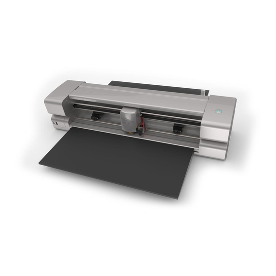
DO NOT touch the cutter with a magnet. DO NOT allow small items to fall into the cutter. TURN OFF the cutter when not in use. 1.04 Parts of the KNK Zing Air Front Limit Switch (red): Blade Holder Seat (aka Jaw) Press Rings... -
Page 11: Accessories
The test pen should be used until you are comfortable with the operation of the KNK Zing Air and know, with certainty, where shapes will cut. To assemble the test pen, remove the top cap, slip the spring over the top half of the pen insert and then drop the pen insert into the bottom half of the pen holder. -
Page 12: Preparing And Caring For The Cutting Mat
(too small to be visible) fibers from the towel are added to the surface. Do not leave the pinch wheels in a down position when the Zing Air isn’t in use. This warps the plastic sooner, shortening the useful life of the cutting mat. -
Page 13: Cleaning And Replenishing The Cutting Mat
1.06.2 Cleaning and Replenishing the Cutting Mat When mats begin to lose their stickiness, they can be washed: Use a mild dishwashing detergent, warm water, and a soft brush to thoroughly clean the surface. You’re not trying to scrub the adhesive but just wet the invisible fibers that have been deposited from your cutting materials and get them released from the glue. -
Page 14: Mat/Material Guides
1.10 Connecting the Zing Air to Your Computer Place your Zing Air on a sturdy horizontal surface. Be sure to allow enough free room in both the front and the back for the mat to extend during cutting. ... - Page 15 (3) Note: it may take a short time for Windows to locate it, so be patient. If it is not located, then verify that the Zing Air is still powered on and is within 30 feet with no obstructions or within 10 feet if an interior wall separates the cutter from the computer.
-
Page 16: Connecting To A Mac
Connecting Via Bluetooth to Another Computer If you need to disconnect the Zing Air from Bluetooth, click on the Bluetooth icon on your task bar and select Show Bluetooth Devices. Devices and Printers will open and you can then select Cutter and then click on Remove Device. -
Page 17: Verify Communication And Test Draw Shapes
New owners tend to be VERY eager to try out their Zing Air. It’s also important to test your cutter to ensure that data is being sent properly from your computer to the cutter. The following steps will allow you to do some testing with the pen tool. -
Page 18: Drawing Your First Shape
In Portrait mode, the arrow on the Cutting Mat will point upwards. When you draw or cut out the “ABC” shown on a Portrait Cutting Mat, it will be drawn or cut left to right as you face the Zing Air: Feed the mat this The shape will be cut Portrait. - Page 19 2. Insert the mat into the cutter. Slide the mat towards the back and use any of the horizontal markings at the front of the Zing Air to align the mat. Lift the pinch levers to drop the pinch wheels onto the cutting mat.
- Page 20 6. After clicking the arrow, you should see it on the screen. In this test, it doesn’t matter where you place the arrow on the grid, as it will be drawn at the origin you set on the machine. 7. In Section 3.01.4, you installed the KNK Zing Air in SCAL. To now open the Cut Settings window, either: Go to Cutter>...
- Page 21 Change the remaining settings to match the prior screenshot. More details about these settings will be covered in othe sections. 9. Click on Set Origin at the bottom of the Cut Settings window. The Zing Air fan will turn on and the following window will open:...
-
Page 22: Maintenance
The pinch wheel levers on the KNK Zing Air may need to be tightened from time to time. If the levers are difficult to operate, use a screwdriver to slightly tighten (clockwise only) the screws on the levers. - Page 23 You will be able to tell based on seeing deep cuts in the strip and an inconsistency in the cutting. Contact KNK USA for information on obtaining a replacement. For any other questions or concerns about maintaining your KNK, please post at our user forum: http://knkusa.com/forums/...
-
Page 24: Zing Air: Cutting
The key to becoming successful at cutting is to do a lot of it! Those who shy away from using their Zing Air will never get to the stage of mastering it. It’s very normal for new owners to be intimidated by their cutter, so remember the following key things: ... -
Page 25: Use The Correct Blade For The Material You Are Cutting
If you do see deep cut lines in your mat, retract the blade length by turning the top of the blade holder ~¼ of a turn counterclockwise. You do not need to remove the blade holder from the Zing Air. Repeat your test cut. Material... -
Page 26: Adjust The Speed, Force, And Number Of Passes Based On The Material And Shapes
Using correct cut settings is equally important as the type of blade, blade length, and blade height. Refer to Section 2.02 for details. Again, some suggested settings are located at the end of this chapter and settings for using the various Zing Air accessory tools are located at the end of Chapter 12. Perform Test Cuts! ... -
Page 27: Know Where Your Images Will Cut
Don’t Get Frustrated, Get Help! Besides having your own Zing Air dealer as your first line of contact, there are user forums, message boards, and Yahoo groups where you can post questions and get answers from other users, dealers, and Sure Cuts a Lot experts. -
Page 28: Controlling Where Shapes Will Cut
Check this box For shapes you do not wish to cut, change the Cut Line Type (on the Style Panel) to Print+Cut Print. Those shapes can then only be printed and will not be sent to the Cut Settings window. This is typically used in Print and Cut applications (refer to Sections 10.01 and 11.04). -
Page 29: Selecting The Tool To Be Used For Cutting
This is the mode selected when you want to print images on your printer and then have the Maxx Air cut them out. Three registration marks are printed, along with your images, from SCAL to your home or office printer. The printout is placed on the cutting mat. -
Page 30: Determining The Cut Settings
12. 2.03.2 Speed The speed is how fast the blade travels while it is in the “down” or cutting position. The Zing Air has 38 speed settings ranging from “snail’s pace slow” to “insanely fast.” ... -
Page 31: Multi-Cut
Offset is too high: bubbles corners are rounded appear at the corners Below are the current Blade Offset settings to use for each of the three types of KNK Zing blades: Red capped blade: 0.3 mm Blue capped blade: 0.4 mm ... -
Page 32: Presets
In general, the blade type doesn’t greatly affect the Overcut required. Try using 1.00 mm. In the event you cut a large closed shape, like an 8” circle, you may find that you’ll need to increase Overcut to 2.00 mm. 2.04 Presets ... -
Page 33: Set Origin
Every time you turn on the Zing Air, the blade carriage will be moved to the same spot. This is called the Home Origin. Now, you can always use that spot to start your cuts and never set a new origin, however, it limits you, somewhat, in situations where you may be performing your test cut at that location but will need to move over to a new location to cut out your shapes. -
Page 34: Resolution Calibration
Now this might be perfectly acceptable for the type of cutting you do. Therefore, it may not even be necessary to do this particular calibration. However, if you do want to make sure your shapes are cut precisely, the following procedure will allow you to calibrate your Zing Air. ... - Page 35 Draw the square on your paper using the test pen or some other thin line pen. Then carefully measure the Width (the left-to-right length that drew) and the Height (the top-to-bottom length that drew: Feed the mat this direction into the Zing Height Width...
- Page 36 New X Resolution = Current X Resolution multiplied by the desired value divided by the actual value = 1.0 * 10 / 9.99 = 1.001 New Y Resolution = Current Y Resolution multiplied by the desired value divided by the actual value = 1.0 *10.00 / 10.01 = 0.999 ...
-
Page 37: Settings Form For Cutting Materials
Settings Form for Cutting Materials Material Brand or Blade Material Type Blade Force Speed Other Comments Source Offset Passes © 2009 - 2017 Sandy McCauley, All Rights Reserved... -
Page 38: Suggested Cut Settings For Various Materials On Knk Zing / Zing Air
Suggested Cut Settings for Various Materials on KNK Zing / Zing Air IMPORTANT: These settings should be used for the initial test cut. Adjustments may be necessary based on the condition of the blade, variations in the material, humidity, condition of the cutting mat, blade tip height, etc. - Page 39 # of Blade Material Type Material Brand or Source Blade Force Speed (Cut/Up) Other Comments Passes Zing Zing Air Cardstock Paper Studio - smooth finish 70-90 10/10 15/15 Tested white, black, and maroon Cardstock Paper Studio - textured finish Red 100-120 10/10 15/15 Tested white &...
- Page 40 # of Blade Material Type Material Brand or Source Blade Force Speed (Cut/Up) Other Comments Passes Zing Zing Air Double Sided Sookwang 40-50 10/10 15/15 Adhesive Sheets Double Sided Stampin Up - #120805 (Sizzix 30-40 10/10 15/15 Adhesive Sheets brand)
- Page 41 # of Blade Material Type Material Brand or Source Blade Force Speed (Cut/Up) Other Comments Passes Zing Zing Air Icing Sheets Cut-N-Frost by PhotoFrost Yellow 20-45 10/10 15/15 1 or 2 Thin sheet version not recommended Cut dull side up: mirror shapes! Force will vary Iron-on Transfer knkusa.com...
- Page 42 # of Blade Material Type Material Brand or Source Blade Force Speed (Cut/Up) Other Comments Passes Zing Zing Air Rhinestone Green from knkusa.com Blue 80-100 10/10 15/15 Peel off backing,place sticky side onto mat Templatel Shrink Film Grafix - clear...
-
Page 43: Scal: Installation, Preferences, And Workspace
3. SCAL: Installation, Preferences, and Workspace This chapter begins the Sure Cuts a Lot User Manual and is based on Version 4.058. 3.01 Installing SCAL 3.01.1 Selecting and Downloading the Software Sure Cuts A Lot 4 (SCAL) can be downloaded from the following link. Note that there are four choices - Mac or PC and then regular or PRO: http://www.craftedge.com/download/download.html ... - Page 44 IMPORTANT: Make sure the version of SCAL you installed matches the registration you purchased. You can verify this by going to Help>About Sure Cuts a Lot. If the wrong version is installed, uninstall this current version and download the correct one. ...
-
Page 45: Installing The Usb Driver
Note that with some brands, such as KNK, adding multiple models may not give separate listings. While KNK Force does show up separately, selecting both Maxx and Zing Air from the model menu only displays once as KNK. The model needed will be selectable later in the Cut Settings window. -
Page 46: Main Scal Screen
Check which cutter to use (select KNK if you have a Zing Air or Maxx Air) 3.02 Main SCAL Screen Below is a screen shot of the main screen in SCAL identifying various elements. Note the names of the... -
Page 47: Language Preference
Throughout this manual, Cutting Mat (capitalized and in bold type) refers to the on-screen simulation of the actual cutting mat, which will be written with lower case, normal type. Shapes are the objects or images that you will be adding to your projects. They can be created from scratch or imported from other sources, such as the Library, your computer, or the eshape Store. -
Page 48: Mat Orientation
Click here to create a custom mat The following window will open where you can enter the dimensions of the mat and provide a name, if you wish to store it for future use: Enter dimensions for the mat Check this box, if you want to save it Enter a name for the new mat Click OK. -
Page 49: Mat Grid
Portrait Landscape The black triangles show the direction the actual cutting mat should be fed into the cutter There are three ways to change the mat orientation: On the Documents Panel under Mat Size: Select Portrait or Landscape here ... -
Page 50: Workspace Alpha
Minor grid lines Major grid line (slightly darker) Major grid lines at 6” Minor grid lines every inch (6” divided by 6 subdivisions) Major grid line (slightly darker) A final grid option involves circular grid lines which can, as an example, be used for cake design. Go to View>Show Mat Cake Circles: 3.05.4 Workspace Alpha ... -
Page 51: Rulers
3.05.5 Rulers The Rulers can be toggled on and off by right-clicking on the screen and selecting Show Rulers. Note that when hiding the rulers, click again on the screen for it to take effect. To change the units displayed on the Rulers, refer back to Section 3.04. 3.06 Customizing the Workspace ... - Page 52 Double click on an icon appears here Fill & Stroke is now open, as well as Document These separate panels can also be resized by dragging them up or down: Drag up/down on the line between the two panels Do the same here ...
-
Page 53: Snap To
To save workspace changes, go to Window>Workspace>Save Workspace. A window will open and you can name this new configuration: Name the new Workspace Click on OK When you now go to Window>Workspace, the new workspace will appear at the top: Custom workspaces will appear here... -
Page 54: Other Preferences
Grid lines turn blue when the pink circle snaps to them Blue lines appear when pink circle snaps to both the left side and bottom of the blue rectangle 3.08 Other Preferences Under Edit>Preferences (or, on a Mac, press Command + ,), you will find a number of other options, some of which you will probably never need to change. -
Page 55: Zooming And Panning
For more details on these settings, go to Appendix C4. 3.09 Zooming and Panning Any of the following methods will allow you to zoom in and out: Hold down the Alt key while rolling the mouse wheel ... -
Page 56: Undo/Redo
Fit to Window: (same as zoom to Cutting Mat) Actual Size: Set zoom at 100% Yet another way to change the zoom level is to select from the drop-down menu on the Status Bar in the bottom left corner of the screen: ... -
Page 57: Help Resources
Page Color Current Page Number Add a new page Delete current page To add a page, either go to Page>Add Page or click the green icon on the Pages Bar itself and the following window will open Change Name, if desired Change Color, if desired Click OK when done ... - Page 58 Click on the Help Panel icon on the Properties Panel to open the user guide to a section based on the currently selected tool Go to Help>Forums to access the SCAL user forum Go to Help>Online Video Tutorials to access a page with links to both videos and written tutorials ...
-
Page 59: Scal: Handling Files And Organizing Layers
4. SCAL: Handling Files and Organizing Layers 4.01 Opening Files 4.01.1 Opening a New File/Project When you launch SCAL, a new blank Cutting Mat will appear with a new blank project opened. To open a new file (start a new project), any of the following can be used: ... -
Page 60: Saving Scal Files
In the case of opening a file from Windows Explorer, an email, or using a drag and drop method, the file will automatically open. Note that other file formats, besides .SCUT can be imported into SCAL4. Refer to Section 4.06. 4.02 Saving SCAL Files ... - Page 61 Drag to expand window My Designs View eshape Store download options options mode Search field Shapes Favorites folder Search Library folder Shapes inside the Basic Shapes subfolder My Designs folder eshape Store folders Scroll to change thumbnail size On the left side you will see the Library folder which contains the included 300 shapes. The number in parentheses, after each subfolder, indicates how many shapes are assigned to that subfolder.
- Page 62 Click here to change to list view A search function enables you to see all of the shapes with a particular word in the name. For example, enter the word leaf and click on the search button: 1. Enter search word 2.
- Page 63 Add File to selected folder Delete Folder Refresh Add Folder Click on My Designs Add subfolders: The shapes in the above screenshot have been added to My Designs but not into subfolders. To create subfolders for additional organizing: Click on the Add Folder icon Right-click on My Designs and select Add Folder from the popup menu ...
-
Page 64: Fonts Tab
Select the folder and do either of the following: Click on the Add File icon Right-click and select Add File from the popup menu A window will open where you can then browse to find the SVG file to be added. You also have the option of selecting multiple files at once to import into that folder. -
Page 65: Projects Tab
Scroll the bar at the bottom to change the size of the lettering. To add a character to the Cutting Mat, left- click on it. While it is far quicker to type out text using the Type tool (again, refer to Section 6.03), this window is the best way to add special characters within a font or when using dingbat fonts. -
Page 66: Layers Panel
Click on the Add Folder icon Right-click on My Projects and select Add Folder from the popup menu After choosing to add a folder, the following window opens and you can name this folder: Input a folder name for a new empty folder Click on OK ... -
Page 67: Parts Of The Layers Panel
Selecting one shape or a layer of shapes on the screen Controlling what is sent to the cutter or printer The Layers Panel can be displayed by double-clicking its icon and hidden by double-clicking the small bar just above its icon: Double click to hide Layers Panel... - Page 68 Layers Menu Layer Type Layer Double click to hide Layers Panel Thumbnail Double click to display Layers Panel Layer Color Layer Name: double click to Hide/Show Layer change name and/or properties Lock/Unlock Layer Add a new folder Delete selected layer ...
- Page 69 Mat and will not be included when printing or cutting the project. Clicking on the dot icon will restore the layer to the Cutting Mat: Layer Hidden: Layer Showing: Lock/Unlock Layer: Click on the dot to the right of the eye icon and the layer will become locked such as shown for the Flower 1 layer.
-
Page 70: Creating Folders And Moving Layers
Click here to open/close a grouped layer This shape is hidden Individual shapes within a group This shape is locked 4.04.3 Creating Folders and Moving Layers As mentioned in Section 4.04.1, each new shape added to the Cutting Mat will initially be assigned to a new layer. - Page 71 Short line with open square: Asterisk layer will be dropped into the Yellow Shapes folder Layer being dragged upwards Now the Asterisk layer is inside of the Yellow Shapes folder and can be seen in the thumbnail for that folder: Note new thumnail image ...
- Page 72 Layers can also be moved out of an existing folder into other folders. In this example, the yellow centers of the flowers in the layers named Flower 1 and Flower 2, can be similarly dragged and dropped into the Yellow Shapes folder: ...
-
Page 73: The Eshape Store
All yellow shapes are selected and Group is applied. New group folder contains these yellow shapes 4.05 The eshape Store 4.05.1 Importing from the eshape Store The eshape Store is an online shopping site linked within SCAL. Cutting files and fonts can be purchased through the store and downloaded into SCAL. - Page 74 Now open the Library to access the eshape Store files. Depending on the file type, the downloaded files will either appear on the Shapes tab, under Design Downloads or on the Projects tab, under Project Downloads: Purchased set of files ...
-
Page 75: Exporting To The Eshape Store
Select time period Click here Or click here to download individual products within Click here to an order download entire order 4.05.2 Exporting to the eshape Store To freely share your own SCAL creations, go to File>Share Project. The following window will open: Start with Info tab Make sure you are logged into the store... - Page 76 Click on Images tab List of image files Click on Add to upload another image <Required> is the default image of the project An additional image Option to change to Click here after Show Video entering all of the info and proofing it ...
-
Page 77: Importing Other File Formats
Click on Instructions tab Click on Preview Type in the instructions A preview of the instructions appears here Import an HTML formatted file by clicking on Add and then selecting the file: Select HTML Click on Preview after adding file Click on Add to upload an HTML file ... -
Page 78: Importing Raster Files
DXF (SCAL PRO version only): common format exported by CAD programs WPC: format used in programs developed by Sign Max, which include WinPC Sign, Funtime, Pazzles Inspiration, and Gazelle. There are two ways to open the import window: ... -
Page 79: Importing Fonts
File>Place Image: will import JPG, BMP, GIF, and PNG files for the purpose of printing or manually tracing in the event the auto-tracing function doesn’t adequately perform due to the image quality. It’s also another way to load an image for the Trace Image window. Refer to Section 7.03. ... -
Page 80: Exporting In Jpg, Png, Bmp And Tiff Formats
Select a Resolution based on the program Check this box to include which will be importing the file PNC registration marks Check this box if you pre-selected certain shapes for exporting versus exporting all Check this box if file will be of the visible layers of the file imported into Cricut’s Design Space software... -
Page 81: Exporting In Fcm Format
Export Settings Preview of image to be exported (note the drop shadow) Drop Shadow settings Click here to see effect of Click on OK settings if Auto Preview is not checked 4.07.3 Exporting in FCM Format The FCM format is used by the Brother ScanNCut models. There is no secondary window with export settings. -
Page 82: Exporting To Scal2
4.07.5 Exporting to SCAL2 If you still use SCAL2, you can send a file from SCAL4 to SCAL2 by going to File>Send to> Sure Cuts A Lot 2. You will need both versions of SCAL open at the time. -
Page 83: Scal: Manipulating And Coloring Shapes
5. SCAL: Manipulating and Coloring Shapes This chapter covers all of the ways to modify shapes. Note that while the singular term “shape” will be repeatedly used when describing various functions, it also refers to a selection of shapes. For example, resizing a selection of three shapes uses the same menu functions or mouse movement as a single shape. - Page 84 In Advanced mode, a selected shape will appear with six identical handles. However, each handle now has two functions, depending on whether the mouse hovers directly over the handle or is moved slightly away from the handle: Cursor indicates Cursor indicates a resize function.
-
Page 85: Deleting
5.02 Deleting To delete a selected shape, use any of the following options: Press the Delete key on the keyboard Right-click on the screen and choose Delete from the menu If the shape is on its own layer, click on the Delete Layer icon: ... - Page 86 Based on center of bounding box New locations for X and Y are entered The Nudge icons, which are just below the X and Y entries, can also be used to move a selected shape. These move in the same increments as the keyboard arrows: ...
-
Page 87: Resizing, Scaling, Autofit
Right side of shape is at X: 3” Bottom of shape is at Y: 4.5” 5.04 Resizing, Scaling, Autofit 5.04.1 Resizing With the shape selected, use your mouse to drag the lower right corner of the shape to freely resize. If you want to keep the width and height proportional, hold the Shift key down before dragging that icon: Drag this icon to resize. -
Page 88: Scaling
Uncheck this box Important: Unchecking this box does not then affect shapes created using the Shapes tool on the Tools Panel. You will need to hold the Shift key to maintain proportions when resizing by dragging the lower right corner. -
Page 89: Rotating
The new size of the circle is 11.875” x 11.875”. If the circle is placed on a 15” x 15” mat, then it resizes to 14.85” x 14.875”. However, if the circle is placed on letter size mat (8.5” x 11”), then it becomes an oval: ... - Page 90 Drag here Or drag here Holding the Shift key, while rotating, will rotate the shape in 15 increments. However, if you need to rotate in increments other than 15 , go to Edit>Preferences, click on the Edit tab, and change the Constrain Angle to the desired increment (from 1 to 180 ).
-
Page 91: Skewing And Distorting
5.06 Skewing and Distorting 5.06.1 Skewing Shapes can be skewed either horizontally or vertically: Starting Shape Horizontal Skew Vertical Skew Both horizontal and vertical skew There are two ways to skew a shape: With the shape selected and Advanced selected on the Tool Options, rest your mouse slightly outside of a handle in the middle of a side. -
Page 92: Mirroring And Flipping
The shape can now be distorted in countless ways by dragging any of the corners : Of course, the shape doesn’t have to be rectangular. The Distort tool can be applied to anything: 5.07 Mirroring and Flipping To horizontally mirror a shape, select it and then use one of the following: ... -
Page 93: Hiding And Showing
To lock a selected shape, use any of the following options: Right-click and select Lock from the menu Go to Object>Lock Press Ctrl+Alt+L Locate the shape on the Layers Panel and click on the unlock icon or double-click and check the Lock option. -
Page 94: Grouping And Ungrouping
To toggle the hide/unhide status of all layers on the Layers Panel, click on the Layers Menu icon select Show/Hide>Toggle All Layers 5.10 Grouping and Ungrouping 5.10.1 Group The Group function is used to combine shapes into a new folder on the Layers Panel so that they can be more easily moved, resized, rotated, etc. -
Page 95: Breaking And Merging
On the Layers Panel: Opening folder shows the three Before applying Ungroup: After applying Ungroup: letters as individual text shapes Layer has Text icon Layer now indicates a folder indicating a single text shape with more than one shape 5.11 Breaking and Merging 5.11.1 Break Apart ... -
Page 96: Merge
Icon changes from Text to Folder Seven individual shapes in the folder Once you apply Break Apart, you have complete editing control over each individual shape within a design. But be careful! It’s also easy to inadvertently move an individual shape (especially the tiny ones) and you can risk messing up the design. -
Page 97: Arranging (Ordering) Shapes
A child shape that is merged with a parent shape essentially becomes a hole in that shape. This can be proven by having the grid showing when merging: The grid is visible indicating a hole. Before applying Merge: After applying Merge: Two shapes: a white Single shape with a star- star on top of a blue star... - Page 98 Bring to Front Triangle moves to the top Bring Forward Triangle moves above blue star but is still below red heart Send Backward Triangle moves below purple square but is still above green circle Send to Back Triangle moves to the bottom ...
-
Page 99: Fill & Stroke: Fill
5.13 Fill & Stroke: Fill The Fill & Stroke Panel provides options for changing how a shape or open path appears on the screen and, in the case of Line Style (solid versus dashed), how it cuts. This can be helpful in designing a project and also in print and cut applications. -
Page 100: No Fill
To select a type of Fill, click on the drop-down menu and select from the four options: Click here 5.13.1 No Fill From the Fill menu, select None and shape will be empty. Note that this is not the same as having a white fill. - Page 101 These will activate if My Patterns is selected below With the Patterns folder Pattern folders selected, these seven default patterns appear. Pattern settings Current selected pattern Click to see a preview of Click OK when done the shape with the pattern ...
-
Page 102: Gradient Fill
Select the Load Image tab Click here to load a raster file Uploaded image Pattern settings Click to see a preview of Click OK when done. the shape with the pattern The selected shape now fills with the uploaded image: 5.13.4 Gradient Fill ... - Page 103 To change colors, click on one of the markers, then click on the color selector box and choose a color from the Color window. Repeat for the other marker. As with other color selections, you can choose a base color or create a custom color: Option 2: Click in the window and then scroll up and down to lighten...
-
Page 104: Opacity
Changing the Position moves the marker and resets where the gradient begins on that side. You can also manually slide the markers to change the Position, as well. Returning to the two-color example: Left marker at 0; Left marker at 35: Right marker at 70 Both markers at 50 Right marker at 100... -
Page 105: Fill & Stroke: Stroke
In the following example, the Opacity is decreased on the blue circle, allowing the blocked portion of the red square to be seen: Opacity: 15 Opacity: 50 Opacity: 100 Lowering the Opacity can be applied to shapes filled with Patterns and Gradients, as well: Opacity: 100 Opacity: 70 Opacity: 100... - Page 106 Fill: None Stroke: None Fill: Color Stroke: None Fill: None Stroke: None Shape is selected Hovering mouse over it Color: Once Color is selected, click on the box to the right and the Color window will open. This is the same window that opened when Color was selected under Fill.
- Page 107 Switch to the new Pen Set Again, click on the small icon in the upper right corner and you can begin adding pen colors with their respective RGB color values or just scroll to create colors you like: Click on Add Color Click on OK After clicking on OK, you will be prompted to name this color and then it wil show up in the menu: The new color is now...
- Page 108 Stroke Width: 1 Stroke Width: 10 Stroke Width: 20 Stroke Width: 20 Opacity: 50% Opacity: 100% Opacity: 100% Opacity: 100% IMPORTANT: The Stroke Width does not affect how a shape or line is cut or drawn. It’s only used for display and printing purposes.
-
Page 109: Dropper Tool
Line Style: The Line Style can be either solid or dashed. If dashed is selected, then one of the default patterns can be selected or you can specify the dash length and spacing desired by clicking on Edit: Select from menu or click on Edit to open Line Style window Enter a dash and gap pattern, as desired. -
Page 110: Cutting, Copying, Pasting, Duplicating
All three shapes recolored at once Shapes recolored individually 5.16 Cutting, Copying, Pasting, Duplicating 5.16.1 Cutting to the Clipboard To cut shapes to the clipboard (copy to the clipboard and delete from the Cutting Mat), first select the shape or shapes and then use any of the following: ... -
Page 111: Duplicating - Duplicate
Right-click on the screen and select Paste in Place (without any shapes selected) Press Ctrl+Shift+V Go to Edit>Paste in Place To Paste (Auto Fill): use either of the following: Press Ctrl+Shift+Alt+V Go to Edit>Paste (Auto Fill) 5.16.4 Duplicating - Duplicate ... -
Page 112: Align To Page
Click on an alignment icon from the Position & Size window on the Properties Panel: Click on Position & Size Check this box to switch to Alignment icons Align to Page The following three shapes, in their current relative positions, will be used to illustrate what happens when each alignment function is applied. -
Page 113: Align To Selection
Align Vertical Center aligns shapes through the center of the Cutting Mat. Align Bottom aligns shapes along the bottom side of the Cutting Mat. Align Top Align Vertical Align Bottom Center To center all three shapes in the middle of the Cutting Mat, use either: ... -
Page 114: Distribute
With the shapes selected, the vertical alignment options are: Align Top aligns shapes along the top side of the uppermost shape of the group. Align Vertical Center aligns shapes to a horizontal axis through the center. Align Bottom aligns shapes along the bottom side of the bottommost shape of the group. -
Page 115: Distribute To Page
5.18.1 Distribute to Page Select the shapes and go to Object>Distribute and then make sure the Distribute to Page option is checked. In this mode, the two outermost shapes will align with the Cutting Mat and then other shapes will be evenly spaced from one side of the mat to the other, according to which additional option is chosen. -
Page 116: Distribute To Selection
Distribute Center Vertically: spaces shapes so that the centers of each shape are the same distance apart: Distribute Bottom: spaces shapes so that the bottom sides of each shape are the same distance apart: Distribute Space Vertically: spaces shapes so that the gaps between the shapes are the same. 5.18.2 Distribute to Selection ... - Page 117 Distribute Center Horizontally: spaces shapes so that the centers of each shape are the same distance apart: Distribute Right: spaces shapes so that the right sides of each shape are the same distance apart: Distribute Space Horizontally: spaces shapes so that the gaps between the shapes are the same. ...
-
Page 118: Distribute To Selection Below
Distribute Bottom: spaces shapes so that the bottom sides of each shape are the same distance apart: Distribute Space Vertically: spaces shapes so that the gaps between the shapes are the same. 5.18.3 Distribute to Selection Below This function is, hands down, the strangest function I have encountered in 10 years of writing technical manuals. - Page 119 Distribute Left Distribute Top Distribute Left: Note that the up/down Y locations remain the same for all of the circles. Distribute Top: The left/right X locations remain the same for all of the circles. Now, let’s make the purple circle that’s both furthest to the right and furthest towards the bottom equal to 3” in size instead of just 1”...
- Page 120 Now, this distribution happened because the purple circle was both larger than the red one AND it was the outermost circle in both of the opposite directions. In other words, when applying Distribute Left, the purple circle was the rightmost shape. When applying Distribute Top, the purple circle was the bottommost shape.
-
Page 121: Scal: Working With Text
6. SCAL: Working with Text 6.01 Text Options There are four modes for adding text to the Cutting Mat: Type Tool: normal left to right typing of text Vertical Type Tool: vertical aligned lettering Type on Path Tool: text is aligned along the path of your choosing ... -
Page 122: Four Modes Of Text
Copy and paste text from another application, such as from Word, Excel, or from an email, onto the Cutting Mat. Before pasting, click on the Type Tool icon on the Tools Panel Click on the Fonts tab in the Library and click on characters shown in the character map. This is the easiest method when using dingbat fonts: Select a font Click on... -
Page 123: Type On Path Tool
6.04.3 Type on Path Tool Determine which shape you want to use for the path. In the prior screen shot, a square was used. But it could have been a curve or any other shape. Hold down the mouse button on the Type Tool icon on the Tools Panel and select the third choice: Type on Path Tool. -
Page 124: Text Settings
Decreasing the Arch Radius from 1.0 to 2.0: Changing the Start Angle from 0 to 180: Changing Text from Outside to Inside: When done, either press the Esc key or click on the Select icon on the Tools Panel. 6.05 Text Settings ... -
Page 125: Other Text Editing
The following is a list of these settings and how to apply them. Note that if the text is already typed, you can highlight all or only a portion of the text for the change. View: Controls which fonts show in the menu under Font: All: Displays all installed fonts plus any that have been temporarily installed during this session of SCAL Favorites: Displays all fonts you have assigned as a Favorite in the Library... -
Page 126: Creating A Connected Letter Title
For more information on Ungroup and Break Apart, refer to Sections 5.10.2 and 5.11.1. 6.07 Creating a Connected Letter Title Using the instructions from Section 6.04.1, type the letters of your title: Because you will be working with the letters individually, select the title and apply Ungroup (Section 6.06). ... -
Page 127: Incorporating Shapes Into A Title
To create an outline/shadow for titles and other shapes or if you need to thicken a font that turns out to be too thin for cutting, refer to Section 9.04. 6.08 Incorporating Shapes into a Title A quick way to incorporate a shape into a welded title is to use any of thousands of dingbat fonts available from the Internet for free or even check the SCAL Library for a shape. -
Page 128: Stenciling Letters
Most crafters will start looking for a different font… one with ligatures (extenders) that easily connect the letters to one another. However, many fonts with ligatures are script fonts and may not convey the desired look. Instead, look for objects that can be used to connect the letters. A basic thin rectangle is an easy solution. -
Page 129: Open Path Fonts (Opf)
Stencil bridge size = 0.10 in Stencil bridge size = 0.05 in Size is a bit too large Size is better suited based on letter sizing Before applying, hide the outside rectangle, so that it’s not affected. You can now drag the mouse across a letter to create a bridge. -
Page 130: Knockout
Currently, this font type only works in a few applications like SCAL and does not install into Windows or on a Mac O/S for use in programs such as Word. To try out using Open Path Fonts, there are some free ones to download here: http://www.iloveknk.com/Support/Software/Open-Path-Fonts/ ... -
Page 131: Title Crawl
After creating the text, move rows of letters together until they almost touch. Reduce spacing between words, but make sure the text is still readable. The text does not need to be all one shape. Thus, you can recolor parts of it if you wish. ... -
Page 132: Other Text Effects
Angle: As the Angle setting is increased, the top of the title will rotate towards you. Decreasing the Angle setting will rotate away: Angle: -45 Angle: -25 Angle: -145 Height: 3.0 Height: 3.0 Height: 3.0 Height: This setting works in an opposite manner to how one would expect. Increasing Height will make the text less rotated whereas decreasing it will make the text more rotated: Angle: -45 Angle: -25... -
Page 133: Scal: Tracing And Drawing
7. SCAL: Tracing and Drawing 7.01 Raster versus Vector All graphics are either raster or vector and there is no third type. While you can often tell by the file format, even that isn’t always a good way to know for certain. For example, a PDF file can be made from either raster images or vector images and some PDF’s will contain both types. -
Page 134: Finding Easy Images To Trace
7.02 Finding Easy Images to Trace What qualifies as an easy image? The obvious answer is “an image which gives you the results you want!” But those who are new to the vectorizing process do not always realize which images are going to be easy and which ones are not. -
Page 135: Trace Function
7.03 Trace Function 7.03.1 Trace Settings To begin the tracing process, open the Trace Image window using one of the following ways: Click on the Trace icon on the Toolbar Go to File>Trace Image Press Ctrl+Shift+T ... - Page 136 Color Layers: choose this mode for multi-color images where you need separate colors, such as for a paper piecing or layered vinyl project and you want underlayers to use for alignment. Two examples follow which illustrate what is produced when Color Layers is chosen: Original image Tracing of image Tracing ungrouped and separated...
- Page 137 Original image Tracing of image if only pink is selected Original image Colors separated Tracing of image if each color is selected Check the Use Alpha Channel box if the imported file is a PNG file with a transparent background. The transparent background is easily indentified by the trace program requiring very little adjustment to other settings.
-
Page 138: Monochrome Trace Of A Colored Image: Effects Of Contrast
Output: Number of Nodes in current trace Check to Show Nodes Scroll to darken or lighten imported in Preview image in the Preview Zoom tools Crop out parts of the image not needed in the trace Preview of tracing Click here after changing settings to see new Preview ... - Page 139 Browse to a Select image folder to trace File name will Click on Open to appear here import the image In this example, a bell pepper image is imported for tracing and the Preview indicates a single trace path around the image: Monochrome is selcted...
-
Page 140: Monochrome Trace Of A Silhouette Image: Effects Of Smooth
7.03.3 Monochrome Trace of a Silhouette Image: Effects of Smooth As mentioned at the end of Section 7.02, silhouette images typically offer an easy trace. In this next example a silhouette cat image is imported into the Trace window. Because this is a silhouette image, Monochrome mode is chosen and the image appears to have traced very well. -
Page 141: Monochrome Trace Of A Detailed Image: Effects Of Detail
7.03.4 Monochrome Trace of a Detailed Image: Effects of Detail The Detail setting can be used to filter out small shapes. Sometimes these shapes are just random pixels that show up from, say, a dirty scanner bed. Other times they are shapes that make up the design but will be too small to cut and are not needed. -
Page 142: Monochrome Trace Of A Png File With A Transparent Background
To have only one trace line, increase the Single Line Threshold setting until there is only a single line showing in the Preview window: Single Line Threshold = 0 Single Line Threshold = 5 Single Line Threshold = 10 double line double line single line... -
Page 143: Color Layers Trace
Select Monochrome Alpha Channel box will appear and be checked if file is Preview – trace a transparent PNG appears and needs no changes to Contrast Regarding a few of the relevant Settings: Contrast: It shouldn’t be necessary to adjust this setting because of the transparent background ... - Page 144 After loading the image and then selecting Color layers, the window will update to show new settings: Scroll to the left to Select Color layers better see the cut lines in the Preview Scroll to select number of colors to identify Preview Colors identified...
-
Page 145: Single Color Trace
Max Colors = 6 produces 5 layers You can also turn off colors by clicking on them. For example, if you do now want the black background traced: Click once on a color to remove it from the trace ... - Page 146 Current color Scroll to the left to Select Single Color better see the cut lines in the Preview Increase Contrast to add similar colors to selection Preview Click here after every change In the screenshot, the initial color identified was a shade of green. In the Preview you can see how many parts of the flower were included as being in the range of that shade.
- Page 147 Now, reopen the Trace window, reload the same image and then click on the color box next to Single Color. A message will popoup indicating you are to click on another color on the Preview: Click on this box ...
- Page 148 You now have several options for completing the trace which involves adding a final outline/shadow layer to the flower: Continue to use Single Color, click on the part of the image that is black, mark the Blackout option: ...
-
Page 149: Draw Functions
7.04 Draw Functions 7.04.1 The Draw Tool The Draw Tool is accessed by clicking on the 5 icon on the Tools Panel. This tool is used to draw straight lines and Bézier curves. It can be a bit tricky to master but just like with many good things- practice makes perfect! Drawing Straight Lines ... - Page 150 Left click to start Move to a 3 location As you approach the Left click and the and left click again and then left click start, watch for the shape will close and fill at a 2 location cursor change. with color Drawing Bézier Curves ...
-
Page 151: Freehand Drawing
Adding and Deleting Nodes Zoom in on the curve, select it, and then click on the Draw Tool icon. To add a node, move the cursor next to the path and watch for the cursor to change. With the cursor right on the path, left-click to add a node: New node has been added Note the cursor has a small... -
Page 152: Brush Drawing
7.04.3 Brush Drawing The Brush tool is accessed by clicking on the 7 icon on the Tools Panel. It is used to freehand draw thick lines. As with the Freehand tool, using a stylus with a graphics tablet will provide the most control. ... -
Page 153: Manual Tracing Using The Draw Tool
Uncheck this option To avoid inadvertently selecting the image while tracing, lock that layer on the Layers Bar: Lock the layer 7.05.2 Manual Tracing Using the Draw Tool Make sure you have read Section 7.04.1 to learn how to comfortably and successfully use the Draw Tool. ... -
Page 154: Editing The Trace
Zoom in as close as possible, but make sure the entire image can still be seen. Click on the Draw Tool icon. Left-click once in the middle of the neckline (see green arrow below). Then click at each point where the curve changes. - Page 155 If you need to move either node, click on the node to be moved and the other node will turn white. Be very precise in clicking as it is easy to miss the node. If that happens, you will need to click the path again to show the nodes.
-
Page 156: Copy, Mirror And Weld To Complete Symmetrical Shapes
Both parts of the sleeve are reshaped Before editing Repeat on the bottom of the dress. The shape you traced should now fit the original image. If it’s not a perfect fit, don’t worry about it! No one will ever know. 7.05.4 Copy, Mirror and Weld to Complete Symmetrical Shapes ... -
Page 157: Scal: Editing
8. SCAL: Editing This chapter covers functions that are used to modify shapes in SCAL as well as prepare shapes for cutting. For functions used in designing, refer to Chapter 9. 8.01 Simplify The purpose of the Simplify function is to reduce the number of nodes. This can be important when cutting small vector shapes in which clustering of nodes in tight locations can sometimes lead to poor cutting. -
Page 158: Split Path
To see the effect of Threshold, uncheck the Show Nodes box. Make sure the shapes haven’t become distorted as a result of applying the current Threshold setting: Uncheck this box Compare this image to the one on the left ... - Page 159 The left side of this paneled door will be separated and made dashed so that the door can be folded to open instead of being cut out Select the shape and click on the Shape Tool icon on the Tools Panel. The nodes will appear on the shape: ...
-
Page 160: Close Path
Left side won’t cut at all Left side will cut dashed Left side will be scored separately 8.03 Close Path The Close Path function can be applied to any open shape, other than a straight line, to join the start and ending nodes with a straight line: ... -
Page 161: Path Offset
8.05 Path Offset Path Offset creates an outline or inline of a shape and will delete the original upon clicking on OK. Note that if you want the original, either make a backup copy or use the Shadow Layer function presented in Section 9.04. - Page 162 Inline version Inline appears as Check this box a black line A practical example of using Path Offset is when you have a font that is too thin to cut at the size you need. Applying a very small Offset can make the difference in whether or not text can be cut at certain small sizes.
-
Page 163: Eraser
Select the Cut layer only Open the Path Offset window. Set the Offset to a small size, such as 0.03”. Be sure to mark the box for Inset Offset. The result is a cut line which will eliminate that white border around the image: Zooming in on the image shows the cut line is now inside the boundaries of the printed image... -
Page 164: Knife And Crop
Keep closed paths Keep closed Keep closed paths Keep closed checked checked paths unchecked paths unchecked 8.07 Knife and Crop The Knife tool can be accessed by clicking this icon on the Tools Panel. Note the tiny triangle in the icon, indicating there are other options available. -
Page 165: Using Crop
8.07.2 Using Crop With the Crop tool, you drag the mouse to marquee-select an area to be retained. Then you press the Enter key to complete the crop. Everything outside of the selected area will be deleted: The top part of this Marquee-select the area After pressing shape will be cropped... -
Page 166: Which Cutting Tool To Use
With the Crop Selection Only box checked, the shape is selected first and then only the bottom half is deleted: 8.08 Which Cutting Tool to Use? Having so many cutting functions to use can make it difficult to know which one to use in a particular instance. -
Page 167: Ruler
Cut up the butterfly without Knife closing the shapes. Used for projects where the shapes are Split: folded along one side instead of cut out Crop Slice off the top and bottom of a word. Used for a popup card. Boolean Join: Cut a shape with any... - Page 168 The mouse is dragged … to here from here… The measurement for a is 1.18” Distance: This is the actual measurement between the starting location and the ending location. In the prior measurement, W is the same as Distance because the measurement was a horizontal one. But measuring the length of “b”...
-
Page 169: The Shape Tool - Path And Node Editing
The mouse is dragged from here… …to here The measurement for c is 51.72 8.10 The Shape Tool - Path and Node Editing Path editing involves moving paths as well as reshaping them. This topic was first introduced in Section 7.05 where you were shown how to draw with the Draw Tool and then curve a straight line path. -
Page 170: Reshaping A Path
Path is moved without changing other dimensions of the shape If instead, the center section had been widened by selecting the path on its right side, then that would have resulted in shortening the section to the right of it: Center section is wider but note effect on the right... - Page 171 Convert Node to Cusp Convert Node Convert Node to Corner to Symmetric Convert Node to Smooth One or more nodes are highlighted and then the appropriate icon selected. These same four functions can also be accessed by right-clicking and selecting Path>Convert Node to. ...
- Page 172 After applying Smooth Nodes option When the newly formed shape is selected again, the Bézier control points appear in a straight line. If you move one, the other will move as well, in order to maintain that straight line: Bézier control Bézier control points points stay aligned...
- Page 173 Convert Node to Cusp: Select all of the nodes Apply Convert Node to Smooth: Select the middle two lower nodes Apply Convert Node to Symmetric: Select the upper three nodes Apply As was shown in Section 7.05.3, you can also drag the path itself to reshape it, if one of the nodes has been converted to Cusp, Smooth, or Symmetric.
-
Page 174: Examples Of Smoothing Curves
8.10.3 Examples of Smoothing Curves The last method shown in the prior section can be used to correct kinks in what should be a smooth curve. For example, let’s say you want to make the following shape have a nice smooth curve: ... -
Page 175: Applications For The Shape Tool
Shape Tool shows nodes After reshaping the After deleting the nodes causing angular shape line into a curve the right side is flat 8.10.4 Applications for the Shape Tool It’s not always obvious when the Shape Tool might be needed. Here are a few examples to keep in mind: ... -
Page 176: Scal: Designing
9. SCAL: Designing 9.01 Where Do I Start with Learning to Design? SCAL offers some excellent easy-to-use designing tools to assist you in creating whatever you can imagine! The best way to learn these tools is to focus on only one at a time and play with settings! You aren’t going to break anything in the software by experimenting and you never know what you might discover! 9.02 Project Info ... -
Page 177: Basic Shapes
Rhinestones Tab Total number of circles/stones Page Colors used Number of circles/stones of each color Diameter of the circles for that color Note: When changing tabs, such as from Colors to Fonts, always take note of the Page number. It will not automatically update to the page you were just checking. -
Page 178: Circle And Oval
Radius: 0.10 Radius: 0.25 Radius: 0.75 9.03.3 Circle and Oval After selecting the Circle shape, drag the left mouse button to form an oval. Holding the Shift key while dragging the mouse will constrict the proportions, resulting in a circle: Freely dragging mouse Holding Shift key 9.03.4 Triangle... -
Page 179: Spiral
In the Tool Options, two settings will appear: The Star points setting can be used to change the number of points on the star. The Inner radius setting can be used to change the angle of the inner points: 5 Points 4 Points, 8 Points... -
Page 180: Shadow Layer
Inner Radius: 0 Inner Radius: 0.2 Inner Radius: 0.5 Clockwise: Whether spiral rotates clockwise or counter-clockwise from center: Clockwise: checked Clockwise: not checked 9.04 Shadow Layer The Shadow Layer function allows you to create an outline or an inline of any shape including, of course, text. - Page 181 Type controls the style or shape of the shadow at the corners. There are three choices: Shadow Shadow (Rounded) Shadow (Straight) Note that the first choice, Shadow, also has a Miter setting which should work in the same way as Miter affects the Stroke (refer to Section 5.14).
- Page 182 Interior is filled Check this box Print +Cut Outline creates a shadow with a Fill and Stroke both set to None. The shadow will be invisible unless you hover the mouse over the shadow: Shadow is invisible unless you hover your mouse over it. Check this box ...
-
Page 183: Boolean Operations
9.05 Boolean Operations Under Path on the Menu Bar, there are five Boolean operations that are very useful when designing cutting files. This section illustrates how each works and provides a practical example for each one. 9.05.1 Union The Union operation, also commonly called welding, removes the overlap between two or more selected shapes. -
Page 184: Intersection
9.05.2 Intersection The Intersection operation is the opposite of the Union operation. Instead of removing overlap, the overlap is what remains. The color of the new shape will be that of the bottom shape: With a Fill color: before and after Intersection With no Fill: before and after Intersection ... -
Page 185: Exclude
9.05.3 Exclude The Exclude operation subtracts the intersection of two shapes from both of the shapes. The color of the new shapes will be that of the upper shape. With a Fill color: before and after Exclude After applying Break and moving one of the shapes After applying Break and moving one of the shapes With no Fill: before and after Exclude ... -
Page 186: Front Minus Back
9.05.4 Front Minus Back The Front Minus Back operation subtracts the intersection of two shapes from the front (or upper) shape, leaving only that front shape: With a Fill color: before and after Front Minus Back With no Fill: before and after Front Minus Back ... -
Page 187: Duplicate Rotated
9.06 Duplicate Rotated 9.06.1 Duplicate Rotated Settings The Duplicate Rotated function allows you to make duplicates arranged in a circle or partial circle pattern. To access Duplicate Rotated, first select the shape(s) and then use either of the following: ... -
Page 188: Using Duplicate Rotated To Design A Wreath
Original Circle Original Circle Last circle Last circle Direction: Counter-Clockwise Direction: Clockwise Does it matter which Direction is used? Most likely, only if you need it for display purposes. Rotate has two options: Evenly and Custom. With Evenly selected, the copies are distributed evenly in a circle. -
Page 189: Using Duplicate Rotated To Design A Frame
Select and go to Object>Duplicate Rotated. Begin increasing Total Copies and the Rotate V Offset until a desired overlapping pattern is obtained: Wreath is formed Begin increasing Begin increasing After creating the pattern, go to Path>Union to remove the overlap and the shape is ready to cut. 9.06.3 Using Duplicate Rotated to Design a Frame ... -
Page 190: Object On Path
Frame is formed Increase V Offset until the four corners look perfect Click on OK and then apply Path>Union. 9.07 Object on Path The Object on Path function can be used to align repeats of a shape along the path of another shape: ... -
Page 191: Designing A Scalloped Oval
Start Offset: This is the distance from the left side of the path to the location of the first shape: Start Offset = 0.5” Start Offset = 1.5” Start Offset = 0 Repeat: Choose Count if you want to specify how many copies to place along the path. Choose Fill Path length if you want the program to automatically fill in the number of repeats that will fill the path using the spacing you enter: Repeats: Count 10... - Page 192 Shape to be repeated should be above the path shape Select the shapes and open the Object on Path window using Effects>Object on Path. The first thing is to mark the Auto Preview option so that all changes will be immediately reflected. Then choose Fill path length so the shapes will be distributed over the entire path.
-
Page 193: Warp A Shape To A Path
9.07.2 Warp a Shape to a Path The Object on Path function can also be used to stretch a shape to fit a path. For example, let’s start with an arrow (from the Library’s Arrows) and a spiral (refer to Section 9.03.7): ... -
Page 194: Remaining Settings
Arrow remains Arrow bends to fit spiral same length Warp to path: On Warp to path: On Stretch to path length: Off Stretch to path length: On 9.07.3 Remaining Settings The two remaining settings in the Object On Path window are: ... - Page 195 Enter Top and Bottom Diameters, as well as the Height of the Tumbler, along the actual surface. Add Template will create the cut line for the tumbler X Offset will move the design left or right on the template. Y Offset will move the design higher or lower on the template Check this box to have Y Scale Resize the design using...
-
Page 196: Lattice
Adjust the X Scale and/or Y Scale to resize the design, if needed. If you want to scale proportionately, mark the Keep Proportions box: Remember to click on Update Preview after each change in the settings. Auto Preview doesn’t currently work. - Page 197 Choose Normal, Choose Normal, Horizontal or Vertical Horizontal or Vertical Settings which will alter the appearance of the lattice Change type of lattice fill Click on OK when done. Click on Preview After clicking on Preview, selected shape will display lattice based on current settings ...
- Page 198 Angle: 0 Angle: 45 Angle: 0 Rotate: 0 Rotate: 0 Rotate: 45 Inverse is used to create a kind of negative lattice and an example will follow later in this section: Inverse not checked Inverse checked An example of when Inverse would not be checked is when you want to attach/weld a latticed shape to something else.
- Page 199 Align the latticed heart in the center of the ring and weld using Path>Union: Remove Fill from ring After applying Set Fill to red again to make overlap easier Path>Union to see An example of when Inverse would be checked is when you want a lattice aperture cut from the front of a greeting card: ...
-
Page 200: Rhinestones
If you have a shape that has the Lattice effect applied and want to remove it (even after the file has been saved and re-opened), select the shape and go to Object>Remove Effects. 9.10 Rhinestones SCAL’s Rhinestones feature provides both outlining and horizontal fill of shapes with the size of circles needed for your rhinestones and the desired spacing. -
Page 201: Rhinestone Fill
Select a Stone Size several numbers larger than your rhinestones Option to Fill shape versus outline Stone Size will update based on what you select in upper window or you can enter a size directly Number of stones based on current settings (must click on Preview first) Select a spacing for the design: usually between 0.5... -
Page 202: Editing Rhinestone Designs
Note this gap Check this option Note new stone count Preview of design The gap in the design is one of the inconsistencies that will sometimes occur with automatic fill algorithms. Thus, all rhinestone designs will need some editing as covered in Section 9.10.4. If you wish to restore the simulation after editing, be sure to record the settings you used before clicking on OK. -
Page 203: Additional Tips On Rhinestone Designing
The following list shows the most common functions applied when editing rhinestone designs: Use the Zoom functions (Section 3.09) to move in close for easier selection of individual or small groups of circles Use the Lasso Selection tool (Section 5.01) to more easily select a group of circles ... - Page 204 For the following example, a swirl design from the Library is added to the Cutting Mat and sized for a T- shirt. The same settings for SS 10 stones will be used - the circles will be 3.4 mm in diameter and the spacing will be 0.5 mm.
-
Page 205: Jigsaw Puzzle
Apply Object>Break Apart to the design. Then decide which half is closer to perfect and delete the other half. Then tweak the remaining half: Break Apart is applied Left side deleted Right side tweaked Select the tweaked design and then perform the following steps shown: Re-apply the Perform a Copy and With the copy selected,... - Page 206 Width and Height: If you plan to apply this puzzle over a specific image, you may want to choose dimensions that correspond to your image. For example, let’s assume you have a photo that is 5” x 3.75” and plan to make a print and cut jigsaw puzzle. Enter those dimensions into the Puzzle Generator, as shown in the prior screenshot.
- Page 207 Select Load Image tab Click on Load Image Click on image and it and browse to find file will appear below Enter the same Size (Width and Height) used when the jigsaw pattern was created and then click on Preview: Enter same dimensions as were used in the Generate Puzzle window...
-
Page 208: Rotate
9.12 3D Rotate The 3D Rotate function is used to rotate a shape along the X, Y, and/or Z axis. To access this function, select a shape and go to Effects>3D Rotate. In the example, text will be used to show the effects of the settings: Rotate along the 3 axes, as desired... -
Page 209: Extrude (Scal Pro Only)
9.13 3D Extrude (SCAL PRO only) The 3D Extrude is used to create a cast or 3D shadow. To access this function, select a shape and go to Effects>3D Extrude. In the following example, text will be used to show the effects of the settings: Option to use Change X and/or Perspective... -
Page 210: Barrel Distortion
Remove Foreground: With this option off, when you separate the shape from the shadow, you see that the shadow is filled beneath the original. In other words, in a paper piecing or layered vinyl project, the original shape would need to be aligned over the top of the 3D shadow: With Remove Forgrounds checked, the original shape will be cut away from the shadow. -
Page 211: Bulge
As you decrease the Threshold, you will see a thickening of the shape in the middle: Threshold = -10 Threshold = -20 Threshold = -40 9.15 Bulge The Bulge feature allows you to apply various expanding or shrinking distortions to a shape. These distortions can be applied to the top side of the shape, the bottom side, or both. - Page 212 The Top Offset rounds the top side of the shape up or down depending on whether a positive or negative value is applied. The Bottom Offset does the same, but applies it to the bottom side of the shape: Top Offset = 1.0 Top Offset = 2.0 Top Offset = -0.5...
-
Page 213: Canned
Effect of Left Curve and Right Curve: Left Offset = 1.0 Left Offset = 1.0 Right Offset = 1.0 Left Curve = 50 Left Curve = 90 Right Curve = 75 Or just have some fun with it: 9.16 Canned ... -
Page 214: Wave
Angle = 0 Angle = 45 Angle = 90 The Diameter of the cynlinder can be increased or decreased, as well. A larger Diameter, applied at the same Angle, will lessen the roundess, while a smaller Diameter will increase it. Angle = -30 Angle = -30 Angle = -30... - Page 215 The Wave function can be used on text to achieve this effect:...
-
Page 216: Scal: Output
10. SCAL: Output 10.01 The Style Panel The Style Panel has various settings that are typically, but not necessarily, applied for the purpose of cutting and printing: Set a contour cut (Shadow) Remove any interior shapes (Blackout) ... -
Page 217: Preview
Refer to last part of Section 10.06.2. Tool: for cutters with more than one head, such as the KNK Force, choose if the layer should be executed by the left side or by the right side. -
Page 218: Printing
On the Cutting Mat: The rounded rectangle is assigned to Cut on the Style Panel The text is assigned to Pen on the Style Panel In the Preview Options window: Red and blue lines Show Cut Lines indicate Cut and and Show Draw Pen assignments Lines are both... - Page 219 Print selection only: This is one way to control what is printed. You will need to select the shapes to be printed prior to entering the Print window. Alternatively, you can hide layers on the Layers Panel that you do not want printed.
-
Page 220: Weeding (Scal Pro Only)
10.04 Weeding (SCAL PRO only) Weeding is an important function for those who do vinyl applications. When removing the waste vinyl from around the cut shapes, it’s very helpful to have extra cut lines. This way you don’t end up trying to weed out large pieces at one time. - Page 221 1 or 5: Add horizontal or vertical weed cuts between shapes and outer weed border 2 or 6: Add horizontal or vertical weed cuts inside the shapes (this is used for applications such as glass etching where the outside “waste vinyl” is actually kept and the shapes themselves are weeded out) 3 or 7: Add horizontal or vertical weed cuts in between shapes and outer weed border and also inside and between shapes...
-
Page 222: Tiling (Scal Pro Only)
In the following example, a design that is 40” wide and 36” tall cannot be cut on a cutter that only has a maximum 15” cutting range (such as the KNK Force): To open the Tiling window, select the shape and go to Effects>Tiling:... - Page 223 Columns and Rows: Under both of these you have the following choices: Evenly spaced: Enter a number and that many columns (or rows) are created, all the same width. For example, you could enter 3 columns and 2 rows: Select Evenly spaced and then 3 Columns and 2...
-
Page 224: Cut Settings
When you are ready to execute a cut (or draw), the cut window can be opened using either of the following: Click on the Cutter icon on the Toolbar Go to Cutter>Cut With KNK Force The following window will open:... - Page 225 Click here to activate a small movement Cutter Settings, which can also be accessed by going to Cutter>Cutter Settings, opens a new window with additional settings relevant to that model. For the KNK Zing Air: Print and Cut Sizing Calibration: Refer settings: Refer to Section 2.08...
- Page 226 Cut Mode Settings: Refer to Section 10.07 which covers controlling where shapes will cut. Choose either Check if only selected WYSIWYG or shapes should be cut Origin Point (refer to Section 10.07) Check either or both if you wish to have shapes mirrored PRO version: enter where before cutting head should go at end of cut...
- Page 227 Click here to delete the KNK Fabric Blade preset If you select Pen under Holder, then an additonal option called Prompt for pen color change will appear. Marking this setting will cause the cutter to pause between colors so that the tool can be changed out, if desired.
- Page 228 Click these buttons or use the arrow keys on your keyboard to move the head left/right and the mat in/out Instructions Click OK once the tool tip is in the desired location for the origin In general, you always set the origin in the lower right corner of the material as was presented in Chapter 1.
-
Page 229: Cut By Color (Scal Pro Only)
In Origin Point mode, it doesn’t matter where the shapes are located on the Cutting Mat, they will cut so as to align with the origin you set: Shapes are aligned with the origin Shapes are aligned with the origin Portrait Landscape Additional details on controlling where shapes are cut are presented in Section 10.07. - Page 230 The Cutting Mat is divided into The shapes of each colors have been quadrants for easier placement arranged into quadrants on the of the scraps onto the actual Cutting Mat cutting mat Let’s say you also have scraps you want to use, however the yellow scrap you plan to use won’t fit onto the mat with the other scraps.
- Page 231 Only the yellow shapes are turned on The yellow scrap is placed in the upper left corner of the mat to match the Preview window Cut each color separately (Separate jobs): In this mode you can also turn or off colors for cutting. However, SCAL will prompt for each color before executing the cut.
- Page 232 Switch to this option Note that you can change the cut order by dragging the colors up or down the menu. For example, let say you already have black vinyl loaded into the cutter and the origin set to cut: The black layer was dragged to the top to cut first ...
- Page 233 cutting. To make the job easier, small registration shapes can be added to the design and cut with every color so that they can then be lined up when layering color. In the Jurassic Park example, three small triangles are added and grouped to be on the same layer: Registration shapes ...
-
Page 234: Tiles (Scal Pro Only)
White shapes are sent to cut Triangles plus white shapes appear in Preview 10.06.3 Tiles (SCAL PRO only) In Section 10.05, you were shown how to use the Tiling function to split a design that is too large to cut based on the limits of your cutter: ... -
Page 235: Extras (Scal Pro Only)
Select Tiles tab Click here to reopen the Tiling window Preview of the tiles- The one outlined in green Partial menu of tiles with corresponds to the one their dimensions highlighted in the menu Cut Tiles: Mark this option first so that the menu and preview appears. ... - Page 236 Select Extras tab Check this box first to then activate other settings Mark this option to use Cutting Mat dimensions or enter actual size of material Mark Autofit or enter Enter desired Spacing for desired numbers of The Preview will update both Columns and Rows as settings are changed Columns and Rows...
-
Page 237: Controlling Where Shapes Will Cut
Landscape – Shapes will cut 90 clockwise to the orientation you see on the Cutting Mat There are 3 available Cut Modes when cutting to the KNK Force: WYSIWYG – Shapes will cut relative to their position on the virtual Cutting Mat ... -
Page 238: Origin Point
IMPORTANT: Both Cut Modes are based on setting an XY origin on the cutter. On a Zing/Zing Air, this origin is set by moving the laser light to the lower right corner of the mat grid or the material. - Page 239 Shapes can be located anywhere on the virtual Cutting Mat. The shapes will be moved and aligned to cut with the origin you set on the material. As mentioned earlier, the origin is set using the position of the laser light.
-
Page 240: Wysiwyg
This corner aligns with the origin in Landscape mode Bounding Box around the shapes This corner aligns with the origin in Portrait mode Also, note that the material can be located anywhere on the cutting mat because you are setting the origin on the material itself. - Page 241 WYSIWYG – Portrait – Cutting Mat Method Feed the mat this direction into the cutter Indicates Portrait mode Shapes are cut in the same location on the actual mat as positioned on the SCAL custom Origin set here Location of shapes in SCAL Where shapes will draw or cut on the material This corner corresponds to the origin on the actual mat...
- Page 242 WYSIWYG – Portrait – Material Method Feed the mat this direction into the cutter Indicates Portrait mode Shapes are cut in the same location The Cutting Mat is on the material as now letter sized to positioned on the match the material SCAL custom mat Origin set here...
-
Page 243: Path Details And Reverse Path
10.08 Path Details and Reverse Path Sometimes a cutting issue can be resolved by reversing the direction of a cut. In SCAL, the cut direction (clockwise versus counterclockwise) can be checked using the following steps: Select the shape, right-click and select Path>Path Details. ... - Page 244 Angle for the lines Enter the spacing between the lines Additional crossing lines Recommended for faster output Recommended if there is no backup Click OK when done Check this box to have the Click here to manually preview update with changes update the preview ...
-
Page 245: Pierce
10.10 Pierce The Pierce function creates holes for punch tools. This can be used to create pergamano designs and paper embroidery patterns. To access this function, select a shape and go to Effects>Pierce: Enter desired spacing between holes Click here to manually Click OK when done update the preview... -
Page 246: Zing Air: Print And Cut
The print and cut process involves printing an image from SCAL to any printer you own and then, with the aid of the Zing Air’s laser having the image or images cut out with perfect precision. Below are three typical kinds of print and cut applications but there are other kinds. -
Page 247: Laser Calibration Procedure
KNK to the next. Also, you will want to use the same blade holder with all of your PNC applications, as the distance can also change with larger or smaller diameter holders. - Page 248 (2) Next change the mat orientation, if needed, so that you are working in Portrait mode. Again, after calibrating you can work in Landscape mode if you prefer. However, in order to use the diagram for adjusting calibration settings, it is very important to use Portrait. Your settings should now look like this: (3) Inside the Basic Shapes folder from the downloaded zip file, you will find the following two files interspersed with the other files: (4) Use File>Import to open whichever one matches the printer paper you’re using, i.e.
-
Page 249: Entering Settings And Printing
C lick here to o pen Fill & Stroke Click here to window open a color menu. Change to Color The arrows will now have a thin black line border. (7) Go to File>Print Setup, select the printer you plan to use, paper size, and Orientation: Select your printer Choose Portrait Verify paper size... - Page 250 Click on Settings Reg mark settings (3) You can modify the settings for the reg mark size, line thickness, and offset from the image to be cut. The latter one, Mark offset, should be changed to 0.03 cm so that the reg marks will be as close as possible to the printed image.
- Page 251 Click on Save IMPORTANT: If you already calibrated your Zing Air using a different software program, enter those same X and Y settings here, however note that the Y value should be entered as a positive number. Thus, if your calibration numbers were, say, X: -0.4 and Y: -24.3, then you would enter them as X: -0.4 and Y: 24.3, again making sure that mm is selected under Units.
-
Page 252: Setting The Registration Marks And Cutting
11.03.4 Setting the Registration Marks and Cutting (1) Place the printout onto the mat and align with the grid. As you are facing the Zing Air, the printout should be on the mat in a portrait orientation with the arrows pointing towards the right end cap. -
Page 253: Preparing An Actual Print And Cut Application
If the red cut line is If the red cut line is If the red cut line is left If the red cut line is right below the black print above the black print of the black print line, of the black print line, line, then decrease line, then increase the then decrease the... -
Page 254: Print And Cut Tips
If the mat is moving numerous times, in and out of the cutter, a slight shifting can occur, especially at high speeds. On the Zing Air, use a speed of 11 or lower. On the original Zing, use a speed of 9 or lower. - Page 255 Make sure you have calibrated your KNK for print and cut (refer to Section 11.03). Also, for this initial tutorial only, please use either Letter sized or A4 sized paper or cardstock. It is very important that you not precut the sheet as this method requires the dimensions to be known and very precise.
- Page 256 Start a new file in SCAL. Go to File>Scan2Cut and the following window will open. Click on Load Image, then browse and select your photo or scan: Click here to load the photo or scan From the Actual Size dropdown menu, choose the dimensions of your sheet. In this tutorial, Letter size is being used, thus 8.5 x 11 is selected.
- Page 257 The next step is to move and perfectly align the four corners of the green rectangle over the four corners of the paper. Before zooming in, use your mouse to drag each of the four red squares “roughly” over those four corners.
- Page 258 Drag square to get Click here perfect alignment to zoom in Drag the scroll bars to move along the green line to another corner and, again, drag the square until the it is perfectly centered with the corner of the paper. Repeat on the other two corners. All four red squares should now be aligned at the corners and you can click on OK: ...
- Page 259 With the image selected, click on the Trace icon on the Toolbar. The Trace Image window will open: Choose appropriate trace settings for the image you are using. You can also use the crop function to reduce the tracing to only include the images and not any of the outside corners of the paper: Crop can be used to eliminate unwanted parts from tracing...
- Page 260 Click on OK. The prior tracing of the image will be deleted (as always happens when using Path Offset. At this point you also no longer need the original graphic. You can either hide that layer or delete it. ...
-
Page 261: Scan2Cut: Additional Methods And Details
11.06.2 Scan2Cut: Additional Methods and Details As was mentioned in the prior section, there are alternative methods that will also work and may be more suitable. Note that these alternatives are presented in a logical order versus a preferential one. My favorite, by far, is Alternative 3 so don’t skip reading it! :-) Alternative 1 Use Custom Registration Marks ... - Page 262 After clicking on one of the colored icons, you will see a larger view here The colored “+” icons need to be dragged over to the dots you drew Note the colors of the “+” signs correspond to the locations of the custom marks ...
- Page 263 The dots are easier for alignment with the laser Having the dots closer to the image versus using the outside corners of the paper allow for more accurate PNC You can skip the second window where alignment is needed with the colored icons ...
-
Page 264: Zing Air: Applications
12. Zing Air: Applications 12.01 Cardstock and Paper Selecting Cardstock White core cardstock does not yield the same cutting quality as solid color core cardstocks. Some cardstock brands or types simply do not cut well. Use those for something else besides cutting intricate shapes. -
Page 265: Chipboard
Demo: Selecting Chipboard There are many types of materials considered to be chipboard. Some can be cut by the KNK Zing Air and others cannot. The best guidelines are: If the chipboard is thicker than the maximum blade length, then it cannot be cut. -
Page 266: Troubleshooting
(adding a few inches for error allowance). Feed the vinyl about half way through the cutter and then drop the pinch wheels. Use the up and down arrows in the Set origin window to feed the vinyl in and out of the Zing Air, to make sure the vinyl stays aligned. ... -
Page 267: Applying Vinyl
with barely any blade exposed. Do a test cut and then gently lift the corner of the vinyl from the backing sheet. Make sure the test cut is a clean cut and the blade did not penetrate the backing paper. ... -
Page 268: Iron-On Or Heat Transfer Vinyl (Htv)
If you are cutting from iron-on which is narrower than this or cutting from scraps, then use a cutting mat to hold the material during the cut. Alternatively, you can tape the iron-on to a wider medium, such as contact paper, and that can serve as a carrier in the Zing Air. ... -
Page 269: Adhering Iron-On
Adhering Iron-On Refer to manufacturer’s recommendations for temperature and time of pressing. At KNK USA’s web site, review the product details to obtain this information. Plan to do a small test on an old T Shirt. Then launder the shirt to make sure the iron-on material stays affixed to the shirt. -
Page 270: Weeding And Brushing In Rhinestones
Peel off the backing sheet first and press the rhinestone material to a clean sticky mat. Brayer firmly to make sure the rubber has excellent contact with the mat. Set Multi-Cut to 2 times, again to aid in weeding the cut circles. Use the blue capped (60 degree) blade for cutting and a force of about 90 for the green rubber and 80 - 85 for the flocks. -
Page 271: Extra Tips On Rhinestone Applications
12.07 Drawing with a Pen or Glue Pen With the Zing Air, you can draw with any pen, pencil, marker, or glue pen, that can be securely gripped by the blade holder seat and not be dragging across the material. The optional... -
Page 272: Draw And Cut: Using The Zing Pen Tool
This may also be a problem with the small press rings. You may want to slide the rings to either side of the Zing Air (next to the pinch rollers), so that they will not smear the ink or glue during the drawing process. - Page 273 In the Cut Settings window, make sure Cut Mode is set to WYSIWYG. Then, change Cut cut lines to Blade/Pen Prompt: Change to WYSIWYG Change to Blade/Pen Prompt Before you begin, make sure you know the settings you’ll need for each pen and for the blade. Because of a current bug in SCAL, you will need to set up Presets for these various combinations of settings so that the preset can be selected at each tool prompt.
-
Page 274: Draw And Cut: When The Pen And Blade Holder Are Not Aligned
After the shapes are drawn, the next prompt will be for the blue shapes. Change out the pen and, again, choose the desired Preset and click on OK. Pen color to be inserted The same Preset is chosen Click on OK to start ... - Page 275 Because the gel pen is thin, it sits further back in the blade holder seat than the blade holder. With no adjustments made, the resulting drawn image and cut circle are out of alignment: However, there is a straight-forward method one can use to compensate for tools with different diameters. This method involves adding a rectangle, within SCAL, around the shapes.
- Page 276 Set an origin and then draw the shapes. Note that it doesn’t matter if you use WYSIWYG mode or Origin Point. Choose whichever one results in having the shapes drawn where you desire on your material. Turn off the layer with the glasses and the circle, but leave the outer rectangle layer turned on. Also, now show the layer with the circle to be cut: Hide the layer with the glasses and the circle...
-
Page 277: Embossing And Scoring
12.08 Embossing and Scoring General Info on Embossing Zing Embossing Tool has two different sized embossing heads. The smaller one is recommended when scoring cardstock for fold-up projects, such as pop-up cards, gift bags, and small boxes. Either head can be used for embossing shapes. -
Page 278: Embossing Leather
Embossing Leather Thank you to Lidia Pallo for providing the following information on embossing leather on a Zing. Note that this same method would apply to other KNK cutters. Use craft-store tooling leather - the kind that comes in ~ 8” X 11” sheets and is about 2-3mm thick. -
Page 279: Project: Engraving A Dog Tag
After the hole is cut in the chipboard, the mat is left in place in the Zing Air! This is important. The cut circle is removed and the actual dog tag is placed inside the cut hole. Tape is used to secure the... -
Page 280: Using The Punch Tool
Don’t forget to set the punch tip height higher, just as you do with the blade holder, in order to get more force applied. 12.11 Cake Decorating Here are some ways to use the KNK Zing Air in cake decorating (thank you to Rebecca Stewart for posting the info in this section): Cupcake wrappers (refer to Section 9.08) ... -
Page 281: Additional Applications
Templates from thin chipboard to use as patterns when cutting thick layers of gum paste Icing sheets can be cut on the regular Zing Air mat, although it’s a good idea to have one dedicated to cake use only. The same is true for the blade holder and blade. - Page 282 are removed. You can remove both before cutting, but you might prefer to leave one of the sheets attached to protect the bottom side from any adhesive on the cutting mat. This bottom sheet can also serve as a stabilizer during the cut. ...
-
Page 283: Suggested Settings For Various Accessories 1
Suggested Settings for Various Accessories Speed (Cut/Up) Application/Material Tool Force Surface Other Comments Passes Zing Zing Air Pen was almost touching paper in order to be grasped by Drawing on paper Sharpie Marker 10/10 15/15 front screw Sharpie Liquid Used 2 passes because pencil hesitates to start drawing... - Page 284 Application/Material Tool Force Speed (Cut/Up) Surface Other Comments Passes Zing Zing Air Embosser - Scoring Cardstock - Bazzill 10/10 15/15 small end Scoring Cardstock - Georgia Embosser - 10/10 15/15 Pacific 100# small end Scoring Cardstock - Embosser - 10/10...
-
Page 285: Settings Form For Accessory Tools
Settings Form for Accessory Tools Speed Application/Material Tool Force Surface Other Comments (Cut/Up) Passes © 2009- 2017 Sandy McCauley, All Rights Reserved... -
Page 286: Appendix A Shortcuts And Icons In Sure Cuts A Lot
Appendix A Shortcuts and Icons in Sure Cuts a Lot Shortcut Icon Description Menu (m:) and/or Icon (i:) Location Main Screen and Project Functions m:File>New Project Ctrl+N Open a new file/project i:Toolbar m:File>Open Project Ctrl+O Open an existing .scut file/project i:Toolbar m:File>Save Project Ctrl+S... - Page 287 Shortcut Icon Description Menu (m:) and/or Icon (i:) Location Importing and Exporting m:File>Import Ctrl+Shift+I Import a file i:Toolbar Ctrl+Shift+E Export a file (save in a different format) m:File>Export m:File>Trace Image Ctrl+Shift+T Open Trace Image window i:Toolbar m:Window>Library Ctrl+1 Open the Library window i:Toolbar m:File>eshape Store Open the eshape store window...
- Page 288 Shortcut Icon Description Menu (m:) and/or Icon (i:) Location Text and Font Icons Open Text Panel i:Properties Panel Bold i:Text Panel Italic i:Text Panel Reload installed fonts list i:Text Panel Add font to Favorites i:Text Panel Type text i:Tools Panel Connect interior shapes to the outside i:Tools Panel Library...
- Page 289 Shortcut Icon Description Menu (m:) and/or Icon (i:) Location Manipulating and Coloring Shapes (continued) Ctrl+Up (or right click>Arrange>Bring Bring selected shape up one level m:Object>Arrange>Bring Forward Forward) Ctrl+Down (or right Send selected shape down one level m:Object>Arrange>Send Backward click>Arrange>Send Backward) Ctrl+Shift+Down (or right Send selected shape to the bottom m:Object>Arrange>Send to Back...
- Page 290 Shortcut Icon Description Menu (m:) and/or Icon (i:) Location Layers Panel (continued) m:Layer>Delete Current Layer Right click>Delete Delete the selected layer i:Layers Panel m:Layer>Add Layer Folder Create a new layer i:Layers Panel Open Layer Options Menu i:Layers Panel Designing Tools Alt+U (or right click>Path>Union) Weld selected shapes to remove overlap m:Path>Union...
- Page 291 Shortcut Icon Description Menu (m:) and/or Icon (i:) Location Editing Tools (continued) Right click>Path>Reverse Path Reverses the direction the path will cut m:Path>Reverse Path Right click>Path>Object to Path Remove the text, rhinestone or lattice status m:Path>Object to Path Close shape by adding a straight line between Right click>Path>Close Path m:Path>Close Path the start and ending nodes...
-
Page 292: Appendix B Troubleshooting Faq's
From the Port menu, select the connection being used based on the following screenshots. While it shows “MaxxAir” under Model, the screenshots will otherwise be the same for the Zing Air. Once you select an option under Port, then click on Test Connection: ... -
Page 293: Operating Issues
____________________ Operating Issues When I first turn on the Zing Air, the blade carriage moves to the right and starts making a terrible noise! There are two black pieces under the pinch bar that need to be removed prior to using the cutter. -
Page 294: Cutting/Drawing Issues
Make sure you raise the pen in the blade holder seat on the Zing Air before tightening the front screw. The blade holder seat needs to be able to drop the pen down when it reaches the spot to draw the shape. - Page 295 Make sure the blade isn’t cutting too deep into the mat. This can sometimes cause the material to be pulled up and away from the mat as the blade releases from the plastic it is cutting. ____________________ My cut is clean in some places but not in others. Why am I not getting consistent cutting? ...
- Page 296 ____________________ The Zing Air stopped during a cut. If the Zing Air stops with the head over on the left side of the cutter, you have most likely exceeded the 14” cutting range. Several things to consider: Check the width (W) of your project (or the height H if in Landscape mode). It cannot exceed 14”.
-
Page 297: Appendix C Scal Details
Appendix C SCAL Details C1 Screenshot of SCAL Screen Below is a screen shot of the main screen in SCAL identifying ONLY Bars and Panels. Menu Bar Toolbar Properties Panel Tool Options Document Panel Page Bar Note: There are other Tools Panel panels accessible on the Properties Panel... -
Page 298: C2.2 Toolbar
C2.2 Toolbar The Toolbar is located at the top of the screen, just below the Menu Bar. Import another Paste from Cut to clipboard: Trace a raster file type: clipboard: Open a saved 5.16.1 import: 7.03 Access eshape 4.06 5.16.3 file: 4.01.2 Store: 4.05... -
Page 299: C3.2 Properties Panel
C3.2 Properties Panel The Properties Panel is located on the right side of the screen and contains 6 subpanels and a Hints access: Document Panel: 3.05 Position & Size Panel: 3.04, 5.01 Fill & Stroke Panel: 5.13, 5.14 Style Panel: 10.01 Text Panel: 6.01... -
Page 300: C4.2 Preferences: Edit Tab
C4.2 Preferences: Edit Tab Click on Edit 5.05 5.03 5.03 See below See below 5.04.1 See below See below See below Restore original Click on OK when done defaults, if needed Keep objects on mat when dragging: With this option checked, you cannot drag shapes beyond the outside borders of the Cutting Mat. - Page 301 Fill: Gradient Fill: Color Fill: Pattern Note that even though the shape appears to be closed, it is not. If you were to cut this shape, it would still be attached to the outside material.
-
Page 302: Acknowledgements
ACKNOWLEDGEMENTS Please send an email to sandy@iloveknk.com if any errors are found in this manual or if you have suggestions for additions or changes. Thank you to the following people for proof-reading this manual. Without their assistance, this manual would be riddled with typos and too many commas! I also greatly appreciate their suggested changes to make things clearer, more consistent, and more accurate: George Crampton...
Need help?
Do you have a question about the Zing Air and is the answer not in the manual?
Questions and answers
Where can I purchase a repalcement On/Off Power Switch for my KNK Zing. Probaly the small PCB (Printed Circuit Board) has died. Paul Stonebridge AUSTRALIA