Table of Contents
Advertisement
Product Manual
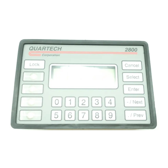
2800
Compact Operator Interface Terminal
for use with
Allen-Bradley ULTRA 3000 Drives
Quartech Corporation
15923 Angelo Drive
Macomb Township, Michigan 48042-4050
Phone: (586) 781-0373 FAX: (586) 781-0378
www.quartechcorp.com
PM2800U3K Revision 4
The product described in this document can have a variety of uses, the user and those responsible for applying this
equipment must satisfy themselves as to the acceptability of each application and the use of the unit. Under no
circumstances will QUARTECH CORPORATION be responsible or liable for any damage, including indirect or
consequential losses resulting from the use, misuse, or application of the unit.
The text, illustrations, charts, and examples included in this document are intended solely to help explain applications
of the product. Due to the many variables associated with specific uses or applications, QUARTECH CORPORATION
cannot assume responsibility or liability for actual use based upon the data provided in this document.
No patent liability is assumed by QUARTECH CORPORATION with respect to the use of circuits, information,
equipment, or software described in this document.
This document is subject to change without notice.
Advertisement
Table of Contents

Subscribe to Our Youtube Channel
Related Manuals for Quartech 2800

Summary of Contents for Quartech 2800
- Page 1 The text, illustrations, charts, and examples included in this document are intended solely to help explain applications of the product. Due to the many variables associated with specific uses or applications, QUARTECH CORPORATION cannot assume responsibility or liability for actual use based upon the data provided in this document.
-
Page 2: Table Of Contents
Table Of Contents Section 1: Introduction..........1 What are Screens &... -
Page 3: Section 1: Introduction
What are Screens & Fields? The 2800 is customized for a particular application by creating screens. A screen is similar to a canned message and may include variable information from the Drive. A group of text or a variable is referred to as a field. Each field has an assigned size and position within a screen. -
Page 4: Numeric Data Field
Page 2 Section 1: Introduction Numeric Data Field This field will display numeric values associated with drive parameters. The parameter from which data will be retrieved is specified when the field is created. Signed and unsigned integer values plus floating point formats are supported. Modification to the value may be enabled or disabled. - Page 5 RPM = 1500 This is the value displayed by the 2800 If the operator enters 750, the 2800 will write the value 100,000 to the Drive.. Raw Value = Entered value / Scale Value Raw Value = 750 / 0.0075 Raw Value = 100,000 This is the value written to the Ultra Drive.
-
Page 6: Recipe Field
Page 4 Section 1: Introduction Recipe Field This field appears as fixed text within a screen. The field can be used in a two different ways. As an Increment/Decrement Function: When the field is created a parameter, Increment/Decrement value, and limit value are specified in addition to the field text. - Page 7 If the Execute method selected for a Recipe field is On Open then a connection to the communication driver is made but the field text is not shown on the 2800 display and the field is not selectable using the Select key. The field will automatically be executed, downloading the parameter list to the Ultra drive.
-
Page 8: Bit Status Fields
AND with Mask Value 0000 0000 0000 0001 Results 0000 0000 0000 0001 The result is equal to the Data Value, therefore, the True Text [STOP] would be displayed on the 2800. Example 2:: Drive Value 0000 0000 0000 0000... - Page 9 Result does not match Data Value so the field text will change to [START]. Lets try the opposite case. Assume the results of example two, the field is currently displaying [START]. You use the Select key on the 2800 to assign focus to this field then press the Enter key. Assumed PLC Value...
-
Page 10: Multi-State Text Field
Page 8 Section 1: Introduction Multi-State Text Field This field monitors an assigned parameter and displays text associated with a specified value. Up to 25 Value/Text Strings can be specified. Entry is allowed with this field. After selecting this field the Next and Prev keys can be used to scroll through the text strings, When the desired text string is displayed, the Enter key can be pressed which will cause the value associated with the text string to be written to the Drive. -
Page 11: Copy Parameters Field
Copy Parameter field. If Execute is set to On Select then the text that is entered when the field is created will be displayed on the 2800 when the screen is displayed. If Execute is set to Link ID then the text that is entered when the field is created will never be displayed. -
Page 12: If Trigger Field
Page 10 Section 1: Introduction If Trigger Field The If Trigger field can be used to trigger a new screen based on the value of an assigned parameter. The If Trigger field will continuously monitor the selected parameter. The value read for the assigned parameter will be ANDed with the Mask Value then the selected Trigger If test will be ran using the limit values. -
Page 13: Section 2: Loading Driver Firmware
Before proceeding the 2800 must be prepared for the download. A four position DIP switch is accessible through the rear cover of the 2800. Applying power to the 2800 with Dip Switch 4 set to the ON position (up), will placed it into System File Download mode. - Page 14 ScreenMaker software to query the attached product and validate its compatibility. The dialog below will display if you forget to press the Next key on the 2800 or if a serial communication link can not be established. The Firmware Download dialog will display if a successful serial link is established.
-
Page 15: Section 3: Loading Project Files
The first step to commission a 2800 is to download Communication Driver Firmware into it. That process was discussed in the prior section. The second step is to download a Project File. The file is downloaded to the 2800 using ScreenMaker 2000k configuration software running on your personal computer. To perform a download the project must be open. - Page 16 Section 3: Loading Project Files Before selecting Connect, insure the 2800 is connected to the computer and ready to receive the download. The 2800 is connected to the computer via serial communication cable, Quartech # 2136-10. To prepare the 2800 for downloading the project file, hold down the Enter key while applying power to it.
-
Page 17: Section 4: Screen Triggering
Section 4: Screen Triggering Assuming the 2800 has been successfully configured with both a Driver Firmware and an a Project it is ready for normal operation. An appropriate communication cable must be connected between the 2800 and ULTRA Driver. The communication cable is available from Quartech and is shown in Appendix A. When power is applied the 2800 will enter the normal Run Mode. - Page 18 Methods of Screen Triggering Triggering screens to the 2800 display can be done in three different ways. The choice is up to the system engineer developing the application. Any of these methods can be used alone or in any combination to create a user friendly application.
-
Page 19: Section 5: Key Definitions
If this field is configured as a Increment or Decrement type then after pressing the Enter key the 2800 will first read the current value from the Drive, add or subtract the assigned value then write the new value back to the Drive. The focus will remain on this field until the Select key transfers it or the Cancel key is pressed.. -
Page 20: Next & ./Prev Keys
These keys are used exclusively for entering values into Drive Data fields or entering field lock codes. Lock Key This key is used to access the global lock code activation / deactivation screen. The 2800 provides fifteen lock codes that can be specified during setup. When a Drive variable field is created using ScreenMaker 2000K, the designer can assign one of the lock codes to the field. -
Page 21: Bit Status Switch
Assume Data Value least significant bit = 1, Momentary option selected. When the F1 key is pressed the 2800 will write the value “1" to the Drive. This is the enabled state. When the key is release no action will be taken. -
Page 22: Jog Button Switch
Page 20 Section 5: Key Definitions Jog Button This configuration allows a Function key to control the Velocity Setpoint variable and can be either momentary or maintained The following examples explain the operation of each mode. If Momentary: When the switch is pressed the specified value is written to the Velocity Setpoint variable in the Ultra Drive. -
Page 23: Section 6: Drive Fault Monitoring
Drive Fault Monitoring The 2800 can be configured to automatically trigger a screen when a drive fault occurs. Up to six drives can be monitored. Every five seconds the 2800 will issue a drive status request. When multiple drives are assigned the 2800 will rotate through the assigned nodes, one every five seconds. -
Page 24: Section 7: Security Locks
Security Locks he 2800 allows a security lock to be applied to variable fields on an individual basis. Up to 15 separate lock codes may be designated. The Lock Data window is accessed via the menu bar Configuration -> Setup 2800. - Page 25 The 2800 allows a global override to be activated on an individual lock code basis. Access to the global override feature is gained by pressing the Lock key on the 2800.
-
Page 26: Section 8: Lcd Contrast Adjustment (Serial Number Prior To 55134)
Section 8: LCD Contrast Adjustment 2800 allows the LCD contrast to be adjusted from the front panel keypad. Applicable to units with serial number prior to 55135. To enter the contrast adjustment mode, press the Cancel and Enter keys simultaneously. You must not be editing a variable field to activate this mode. -
Page 27: Dip Switch Assignments
Page 25 Section 8: LCD Contrast Adjustment PM2800U3K Revision 4... -
Page 28: Appendix A: Electrical/Mechanical Specifications
Appendix A: Electrical/Mechanical Specification A power input terminal block, serial communication interface connector and DIP switch are accessible through the rear cover of the 2800. A description of each is found below. Input Power: A removable three position terminal block is provided for wiring 24 VDC source power. - Page 29 Page 27 Appendix A: Electrical/Mechanical Specification Enclosure Door Cutout The 2800 is designed to be mounted in the door of an enclosure or on an operators console. Care must be taken to prevent metal chips or other conductive particles such as wire clippings from entering the unit.
-
Page 30: 2136 File Download Cable
Use the 2136 RS-232 communication cable between the 2800 and your personal computer. If you computer does not have a serial port then use a USB Serial Adapter. Quartech software and devices have been tested using the TRIPP-LITE KEYSPAN model USA-19HS USB Serial Adapter... -
Page 31: 2162Communication Cables (Rs-485 Single Drive)
Page 29 Appendix A: Electrical/Mechanical Specification 2161 Communication Cable Use this cable to connect to the drive using RS-232. This cable is only available in a length of ten feet. PM2800U3K Revision 4... -
Page 32: 2167Communication Cables (Rs-485 Multiple Drives)
Page 30 Appendix A: Electrical/Mechanical Specification 2162 Communication Cable Use this cable to connect to a single drive using RS-485. The standard length of this cable is ten feet, however, longer lengths can be provided upon request. PM2800U3K Revision 4... -
Page 33: 2174Communication Cables (Rs-232 Multiplexer)
Page 31 Appendix A: Electrical/Mechanical Specification 2167 Communication Cable Use this cable along with the 9109K adapter to connect to a single or multiple drives using RS-485. The standard length of this cable is ten feet, however, longer lengths can be provided upon request. PM2800U3K Revision 4... - Page 34 Page 32 Appendix A: Electrical/Mechanical Specification 2174 Communication Cable Use this cable to connect the 2800 to either input port of the Quartech 9120 Two Port Multiplexer. PM2800U3K Revision 4...
-
Page 35: Appendix B: Error & Warning Messages
Category 2, Configuration & Communication Errors. The messages in this category may vary depending on the Host device that is being used with the 2800. In most cases these messages are self explanatory. Below is a sample of some common messages that may be displayed. - Page 36 If a value is placed into either Trigger Word that is greater than 500 or is equal DOES NOT EXIST to a non-existent screen number in the 2800, then one of these two messages SCREEN # ---- would appear. Either will cause the 2800 to halt operations.
Need help?
Do you have a question about the 2800 and is the answer not in the manual?
Questions and answers