
Subscribe to Our Youtube Channel
Related Manuals for Parker icountPD


Summary of Contents for Parker icountPD
- Page 1 User Manual B.84.833_IPD_GB_Ver A © 2010, Parker Hannifin Corporation www.parkerhfde.com www.comoso.com...
-
Page 2: Laser Information
RS232, 4-20mA, 0-3/0-5V and CANBUS (J1939) outputs • icountPD with or without a Mositure Sensor • icountPD fitted with the fixed 5 metre cable, Deutsch connector or M12 connector. • EN61000-6-3:2001 Electromagnetic compatibility – Part 6-3: Generic standards – Emission standard for residential, commercial and light-industrial environments. -
Page 3: Table Of Contents
Variable voltage output settings .............26 CAN-bus network output option ............26 Moisture sensor output settings ............26 RS232 connectivity ..................27 Software ................28 icountPD Setup Utility software .............28 Microsoft Windows HyperTerminal connection ........31 ® Communication protocol ................33 Front panel displays .............. 37 LED display parameters (ISO4406 / NAS1638) ........37... -
Page 4: Introduction
The shorter the Measurement Period the more sensitive the icountPD is to small slugs of contaminant, but also the performance on clean systems can be reduced. Thus, the user can select how sensitive the icountPD is to spikes of contaminant, and how quickly it responds to contamination levels above the set point (‘limits’). -
Page 5: Benefits
■ ■ (SAE J1939) – see the ‘Product Configurator’, page 53, for communication options Percentage saturation reporting through an integrated moisture sensor – see the ‘Product ■ ■ Configurator’ on page 53, for moisture sensor options. Parker Hannifin icountPD www.comoso.com... -
Page 6: Technical Specification
+5°C to +80°C (+41°F to 176°F) Computer compatibility Parker recommends the use of a 9-way D-type connector. This can be connected to a USB port using a USB-serial adaptor. Note that these connectors/adaptors are NOT supplied with icountPD units: contact Parker Hannifin for advice. -
Page 7: Software Default Settings
Default if options fitted Relay hysteresis Relay operation for particle limits Relay operation for moisture sensor limits Digital display orientation 0 degrees Digital display brightness level 3-mid 0–5V/0–3V output voltage range 0–5V Moisture sensor limit Parker Hannifin icountPD www.comoso.com... -
Page 8: Product Features
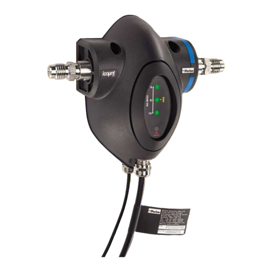
IntRoDUCtIon Product features M16 x 2 test points LED or digital display. icountPD mount points to suit M5 socket Note: 5/8 inch BSF test points for head cap screw (see detail below). phosphate ester fluid application only. Fluid compatibility Blue band = Mineral based oils Red band = Phosphate ester oils. -
Page 9: Connections
If these test points are not required please contact Parker Hannifin for alternative options. Note that the phosphate ester oil version of the icountPD is supplied with 5/8 inch BSF hydraulic test points. -
Page 10: System 20 Sensor Connection
IMPORTANT NOTE: P1 and P2 of the System 20 sensors MUST be connected to the icountPD test points. Ensure that the icountPD command ‘SSU’ is set to ‘Yes’ when connecting to icountPD – refer to ‘Communication protocol’ section of this manual for a list of user commands. -
Page 11: Electrical Connections
ConnECtIonS Electrical connections The icountPD has a Communications cable (in front) and a Supply and Limit relay cable (behind). Supply and Limit Communication cable relay cable Depending on user requirements and the type of installation, the two cables may be supplied in... - Page 12 NOTE: If the moisture sensor is fitted without either 4–20mA or 0–5V/0–3V option then the output is via RS232. * NOTE: Parker Hannifin recommends the use of a 9-way, D-type socket for use with RS232 with the stated pin configuration IMPORTANT NOTE: It is the responsibility of the end user to ensure that the cable’s...
- Page 13 ConnECtIonS 5 metre cable (no connector): voltage measurement Parker Hannifin icountPD www.comoso.com...
- Page 14 ConnECtIonS 5 metre cable (no connector): Current measurement Parker Hannifin icountPD www.comoso.com...
- Page 15 NOTE: If the moisture sensor is fitted without the 4–20mA or the 0–5V/0–3V option, then the output is via RS232. * Parker Hannifin recommends the use of a 9-way D-type socket with RS232, using the pin configurations given in the above table.
- Page 16 ConnECtIonS M12 connector: voltage measurement Parker Hannifin icountPD www.comoso.com...
- Page 17 ConnECtIonS M12 connector: Current measurement Parker Hannifin icountPD www.comoso.com...
- Page 18 NOTE: If the moisture sensor is fitted without the 4–20mA or the 0–5V/0–3V option, then the output is via RS232. * NOTE: Parker recommends the use of a 9-way D-type socket with RS232, using the pin configurations given in the above table.
- Page 19 Parker Hannifin recommend that the mating Deutsch connector cables are screened. These cables are available from Parker Hannifin – see the ‘icountPD part number specifier’ section in this manual. IMPORTANT NOTE: It is the responsibility of the end user to ensure that the cable’s braided screen is terminated to a suitable earth bonding point.
- Page 20 ConnECtIonS Deutsch Dt connector: voltage measurement Parker Hannifin icountPD www.comoso.com...
- Page 21 ConnECtIonS Deutsch Dt connector: Current measurement Parker Hannifin icountPD www.comoso.com...
- Page 22 Pin 8 Pin 8 Product supply 9–40Vdc+ Pin 9 Pin 9 (Red) Pin 10 Pin 10 Pin 11 Pin 11 Screen Screen Pin 12 Pin 12 CAN ground CAN Controller CAN Lo (e.g. Parker IQAN) CAN Hi Parker Hannifin icountPD www.comoso.com...
- Page 23 Once all contacts are in place, insert the orange wedge. Receptacles: with half-holes aligning with contacts. Plugs: with the contacts aligning behind full holes. The orange wedge snaps into place. (The receptacle is shown in this picture – use the same procedure for the plug.) Parker Hannifin icountPD www.comoso.com...
- Page 24 To remove the contacts, pull the wire back gently, at the same time releasing the locking finger by moving it away from the contact using a small screwdriver. Hold the rear seal in place, because removing the contact will displace the seal. Parker Hannifin icountPD www.comoso.com...
-
Page 25: Variable Current Output Settings
Note: * = Saturation (above NAS code 12) NAS v. output mA The actual calculation is as follows: NAS code = (output in mA – 5) e.g. 15mA – 5 = NAS 10 * = Saturation (i.e. above NAS code 12) NAS code Parker Hannifin icountPD www.comoso.com... -
Page 26: Variable Voltage Output Settings
(N.S. = Not Supported) Can-bus network output option If you plan to use the icountPD with a CAN-bus (SAE J1939) network, you can order this output option when specifying the icountPD. Refer to the ‘Product configurator’ (page 53) in the Reference section of this manual. -
Page 27: Rs232 Connectivity
ConnECtIonS RS232 connectivity Communication can be established between icountPD and a PC using an RS232 serial connection with the Parker Utility Setup Tool, the Parker Terminal utility, or via Microsoft Windows ® HyperTerminal. Please note that HyperTerminal is not supplied with Windows Vista , but the Parker Utility Setup ™... -
Page 28: Software
PC Installation The icountPD Setup Utility and Parker Terminal software is available on the CD supplied with the icountPD. The software can be run directly from the CD or copied to a PC hard drive. Using the icountPD Setup Utility Check that the icountPD is connected to power and the communication cable is connected to the PC via the RS232 plug. - Page 29 SoFtWaRE Step 2: Set the values for ‘Detector ID’ and ‘Date Format’. The remaining detector information is preset by Parker Hannifin and cannot be changed. Step 3: Set the values in ‘Measurement Configuration’, ‘Relay Options’ and ‘Alarm Limits’. Step 4: Set the values for Orientation and Brightness Level in ‘Display Options’...
- Page 30 SoFtWaRE Step 5: Setup values are verified as valid in ‘Results’. Click ‘Start’ to start verification and ‘Stop’ to stop. Parker Hannifin icountPD www.comoso.com...
-
Page 31: Microsoft Windows ® Hyperterminal Connection
Hyperterminal connection ® An alternative way of achieving communication with icountPD is to use the HyperTerminal program supplied with Microsoft Windows (but not always installed on the PC or laptop’s hard disk – check the installation disk, or contact your organisation’s IT department if the program is not present). - Page 32 Enter the communication settings (as in the ‘standard communications settings’ table, on the previous page). Step 6: Once the icountPD is connected to power, the product identification is displayed. This identifies successful communication to icountPD. The icountPD is now ready for operation.
-
Page 33: Communication Protocol
SoFtWaRE Communication protocol The commands used with the icountPD are either made up of Set, Read or Start/Stop commands. Set commands allow the value or values of parameters to be changed Read commands allow the value or values of parameters to be read Start/Stop commands allow the user to start and stop tests. - Page 34 Read Communication Echo ‘ON’ or ‘OFF’ displayed Comms Echo ON allows the icountPD to communicate in two directions (Hyperterminal) Comms Echo OFF allows the icountPD to communicate in one direction (Setup Utility) Read DIsplay Brightness Brightness levels 1–5 Read the next calibration Due Date...
- Page 35 Set Communication Echo SCE on SCE off Comms Echo ON allows icountPD to communicate in two directions (Hyperterminal) Comms Echo OFF allows icountPD to communicate in one direction (Setup Utility) Set Display Brightness Set levels 1–5 Set Date Format SDF dd/mm/yy...
- Page 36 With the Power-on Mode set to ‘Auto’ icountPD starts testing automatically when the power is connected using the last setup parameters. With the Power-on Mode set to ‘Manual’ icountPD becomes idle and requires the user to manually start testing. Set Reporting Interval SRI mm:ss (0 to 3600 seconds (i.e.
-
Page 37: Front Panel Displays
LED 3 LED 4 The icountPD uses LED 1, 2 and 3 for the indication of ISO 4406; LED 2 alone is used for the NAS1638 code. Individual code lights trigger according to user settings. The order of triggering is: Solid green trips at all codes below the set point (limit) code. -
Page 38: Digital Display Parameters (Iso 4406 / Nas 1638)
1. Once the icountPD has been connected to a regulated power supply, the product logo is displayed for approximately five seconds as the icountPD performs a system diagnostic check. 2. If the Power-on mode is set to Auto – the factory default – the icountPD automatically starts monitoring, using the default test parameters. MTD calibrated... - Page 39 The icountPD brightness level default is 3. The brightness levels range from 1 (low) to 5 (high), 3 being the mid-point.
- Page 40 Error 20 Number out of range Error 30 Interval shorter than duration Error 40 Expected On or Off Error 41 Expected Disabled or Enabled Error 43 Expected Auto or Manual Error 45 Expected Yes or No Parker Hannifin icountPD www.comoso.com...
-
Page 41: Reference
The relay contacts can be used to switch an external device on or off. Each wire within the icountPD limit relay cable is identified as Red, White and Blue which corresponds with the diagram below. - Page 42 (Normally Closed), the limits set to ISO 20/18/13 and the relay cable electrically connected to a Parker 10MFP Filtration Trolley. The icountPD will activate the 10MFP as soon as the set limits are breached. The ten test results below show the effect of having the hysteresis on or off:...
-
Page 43: Interpreting Data
� � � � � � � � � �� �� �� Particle size, µm Note that interpolation (i.e. estimation within the measured range) is acceptable; extrapolation (i.e. estimation outside of the measured range) is not. Parker Hannifin icountPD www.comoso.com... - Page 44 64 and up to and including 130 particles equal to or larger than 14µm (c) per 100 ml. But the 14µm (c) part of the code could actually be 7, indicating a particle count more than 130 particles per 100 ml. Parker Hannifin icountPD www.comoso.com...
- Page 45 � � ��������� � �� � � � � � � � � � �� �� �� � � � � � � � � � �� �� �� �� �� �� �� particle size µm Parker Hannifin icountPD www.comoso.com...
- Page 46 Size range µm 5–15 15–25 25–50 50–100 >100 1000 2000 4000 8000 1425 16,000 2850 32,000 5700 1012 64,000 11,400 2025 128,000 22,800 4050 256,000 45,600 8100 1440 512,000 91,000 16,200 2880 1,024,000 182,400 32,400 5760 1024 Parker Hannifin icountPD www.comoso.com...
-
Page 47: Iso/Nas/Sae Comparison Chart
6300F 19/16 20/13 6300 20/17 21/14 15,000 21/18 22/15 21,000 23/17 100,000 The above comparisons relate to particle count data only. To confirm to any particular standard, reference should be made to the recommended experimental procedure. Parker Hannifin icountPD www.comoso.com... -
Page 48: Component Cleanliness Guidelines
250,000 16,000 Average Low pressure heavy industrial Gear pumps, manual systems, or applications where and poppet valves, long life is not critical. cylinders 1,000,000 64,000 Main Low pressure systems with large Ram pumps protection clearances. Parker Hannifin icountPD www.comoso.com... -
Page 49: Viscosity Charts
If the fluid you wish to analyse has a relative viscosity of 400 cSt, a 4 bar differential pressure would result in 130 ml/min. Flow x Differential pressure x Viscosity Flow rate (ml/min) Flow x Differential pressure Flow rate (ml/min) Parker Hannifin icountPD www.comoso.com... -
Page 50: Iso Contamination Charts
� � � �� � � � � � � � � � � �� �� �� � � � � � � � � � �� �� �� �� �� �� �� particle size µm Parker Hannifin icountPD www.comoso.com... - Page 51 � � � �� � � � � � � � � � � �� �� �� � � � � � � � � � �� �� �� �� �� �� �� particle size µm Parker Hannifin icountPD www.comoso.com...
- Page 52 � � � �� � � � � � � � � � � �� �� �� � � � � � � � � � �� �� �� �� �� �� �� particle size µm Parker Hannifin icountPD www.comoso.com...
-
Page 53: Ordering Information
The M12 cable kit consists of two 5 metre cables (a communications cable and a relay/power supply cable) that enable all output options. Note that the Aggressive fluid hoses are provided as a single hose, not in pairs. Parker Hannifin icountPD www.comoso.com... - Page 54 STI0144100 ³ / STI.0144.100 6–25 Mineral fluid STI1144100 STI.1144.100 20–100 Mineral fluid ¾ STI2144100 STI.2144.100 80–380 Mineral fluid 1¼ STI0148100 STI.0148.100 6–25 Aggressive fluid STI1148100 STI.1148.100 20–100 Aggressive fluid ¾ STI2148100 STI.2148.100 80–380 Aggressive fluid 1¼ Parker Hannifin icountPD www.comoso.com...
- Page 55 www.comoso.com...
- Page 56 Tel: +27 (0)11 961 0700 NZ – New Zealand, Mt Wellington parker.southafrica@parker.com Tel: +64 9 574 1744 www.parkerhfde.com © 2010 Parker Hannifin Corporation. All rights reserved. European Product Information Centre (24-hour) B.84.833_IPD_GB_Ver A Freephone: +00800 27 27 5374 (from AT, BE, CH, CZ, DE, EE, ES, FI, FR, IE, IT, PT, SE, SK, UK) www.comoso.com...
Need help?
Do you have a question about the icountPD and is the answer not in the manual?
Questions and answers