Advertisement
Available languages
Available languages
Quick Links
Advertisement
Chapters

Related Manuals for Dovre 750 GA


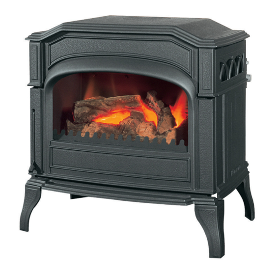
Summary of Contents for Dovre 750 GA
- Page 1 INSTALLATIEVOORSCHRIFTEN EN GEBRUIKSAANWIJZING GASKACHEL INSTALLATION ET MODE D’EMPLOI POELE A GAZ INSTALLATION INSTRUCTIONS AND OPERATING MANUAL GAS STOVE EINBAUANLEITUNG UND GEBRAUCHSANWEISUNG GASOFEN 750 GA 750 GAP 03.27921.100 - 01/2016...
-
Page 2: Table Of Contents
Inhoud 1 installatievoorschrift 1.1 Plaatsbepaling 1.2 Aansluiting op het schoorsteenkanaal 1.5 Toegang tot de branderunit (voor onderhoud of herstelling) 1.3 Aansluiting op de gasleiding 1.4 Installeren van de keramische houtblokken 1.6 Afvoerbeveiliging 2 Gebruiksaanwijzing 2.1 Aansteken 2.3 Werking sfeerbrander (voorste brander) 2.4 Doven van de kachel 2.5 Afvoerbeveiliging 3 Onderhoud... -
Page 3: Installatievoorschrift
1 installatievoorschrift Het plaatsen en in werking stellen moet door vakmensen geschieden volgens de gangbare normen NBN D51-003. Laat bij het in werking stellen, uw installateur u inlichten over het gebruik, bediening en onderhoud van uw toestel. Elk toestel is getest, nauwkeurig afgeregeld en verzegeld in de fabriek gelijkvormig de categorie 12E+(aardgas) of de categorie I3+(propaan/ butaan). -
Page 4: Toegang Tot De Branderunit (Voor Onderhoud Of Herstelling)
1.3 Aansluiting op de gasleiding Controleer of de gassoort en de gasdruk ter plaatse overeenkomen niet de aanduiding op het typeplaatje. In de gastoevoerleiding moet een gekeurde B.G.V. gaskraan zo dicht mogelijk bij het toestel worden gemonteerd. De aansluiting dient spanningsvrij te geschieden. Kontroleer de toevoerleiding op gasdichtheid (door middel van bv. -
Page 5: Afvoerbeveiliging
1.6 Afvoerbeveiliging Bij vervanging, alleen originele clixon toepassen, geen alternatief. De clixon-houder kan gedemonteerd worden door de 2 plaatschroeven op de achterwand los te schroeven. Mogelijke oorzaken die kunnen leiden tot het inschakelen van de afvoerbeveiliging zijn: Een slechte verbinding tussen de kachel en het afvoerkanaal. Het afvoerkanaal is geheel of gedeeltelijk afgedicht door vallend puin of iets dergelijks. -
Page 6: Aansteken
2.1 Aansteken Open de gasafsluitkraan die in de gasleiding naar het toestel is gemonteerd. Draai de thermostaatknop op ontstekingspositie (pilot) en druk deze in (ingedrukt houden). De ontstekingsknop geheel indrukken tot U een “klik” hoort; dit is de vonk-ontsteking. Via het glasraam kunt U zien of de waakvlam brandt. Zonodig enkele malen opnieuw “klikken’... -
Page 7: Onderhoud
3 Onderhoud Bij het begin van ieder stookseizoen is het aan te raden over te gaan tot een grondige ontstoffing van het toestel. Beschadiging aan de verf kan U gemakkelijk bijwerken met een spuitbus “Thermoblack”. In het begin zal de verf van uw kachel nog een geur afgeven. Dit verdwijnt echter vanzelf. Laat het toestel nooit werken met open deur of met een gebarsten of gebroken ruit. -
Page 8: Afmetingen
5 Afmetingen 750 GA(P) wijzigingen op grond van technische verbeteringen voorbehouden... - Page 9 Contenu 1 Instructions d’installation 1.1 Choix de l’emplacement 1.2 Raccordement au conduit de cheminée 1.3 Raccordement â la conduite de gaz. 1.4 Installation des bûches en céramique. 1.5 Dépose de l’unité brûleur (pour entretien ou réparation) 1.6 Dispositif protecteur d’écoulement 2 Mode d’emploi 2.1 L’allumage 2.2 Fonctionnement du thermostat...
-
Page 10: Instructions D'installation
1 Instructions d’installation L’installation et la mise en service doivent être effectuées par un installateur agréé et être conformes aux normes NBN DS 1-003. A La mise en service, informez-vous chez l’installateur de l’emploi et de 1’ entretien de 1’ appareil. -
Page 11: Installation Des Bûches En Céramique
conviennent. Pour des conduits au-delà de 10 mètres, il faut prévoir 1/2”G ou 13/15 en cuivre. 1.4 Installation des bûches en céramique. Ouvrez la porte. Les bûches en céramique sont emballées séparément du fait de leur fragilité. Attention au déballage. Bien respecter le plan pour les positionner correctement. -
Page 12: Mode D'emploi
2 Mode d’emploi Attention: Après l’installation de l’appareil, nous vous conseillons de le faire brûler à la plus haute position et en même temps de bien ventiler, afin que la peinture puisse se stabiliser. Une buée blanche sur la vitre est possible pendant la première période. Avec un chiffon on peut la nettoyer quand l’appareil est froid. -
Page 13: Fonctionnement Du Thermostat
Donnez une impulsion sur le bouton d’allumage jusqu’à ce que la veilleuse s’allume, celle-ci étant visible au travers de la vitre. Répétez si besoin jusqu’à ce que la veilleuse s’ allume. Quand la veilleuse est allumée, maintenez le sélecteur de température encore environ 30 secondes avant de le relâcher. -
Page 14: Entretien
Il est recommandé de dépoussiérer l’intérieur du poêle de temps en temps même pendant la saison de chauffe. Si la peinture, se détériore, une application de notre “Thermoblack” rénovera facilement l’aspect extérieur. N’utilisez que les aérosols Dovre. En cas de bris ou fêlure de vitre, la remplacer immédiatement. -
Page 15: Dimensions
5 Dimensions 750 GA(P) wijzigingen op grond van technische verbeteringen voorbehouden... - Page 16 Table of contents 1 Installation instructions 1.1 Choosing a location 1.2 Connection to the flue pipe 1.3 Connection to the gas supply 1.4 Installing the ceramic logs 1.5 Access to the burner unit (for maintenance or repairs) 1.6 Outlet protection 2 Instructions for use 2.1 Ignition 2.3 Using the effects burner (front burner)
-
Page 17: Installation Instructions
1 Installation instructions The installation and start-up must be carried out by specialist installers in accordance with the NBN D51-003 standard. During installation, have your installer explain how to use, operate and maintain your appliance. Each appliance is tested, carefully adjusted and sealed in the factory in accordance with category I2E+ (natural gas) or category I3+ (propane/butane). -
Page 18: Connection To The Gas Supply
1.3 Connection to the gas supply Check whether the gas type and the gas pressure correspond to the indications on the identification plate. An approved AGB/BGV gas valve must be fitted as close as possible to the appliance. The connection must be tension-free. Check that the gas supply pipe has no leaks (e.g. -
Page 19: Outlet Protection
1.6 Outlet protection On replacement, only use the original thermal switch, not alternatives. The thermal switch holder can be removed by unscrewing the two self-tapping screws on the rear wall. Possible causes for the activation of the outlet protection include: A bad connection between the stove and the outlet flue. -
Page 20: Ignition
2.1 Ignition Open the gas valve fitted in the gas pipe to the appliance. Turn the thermostat knob to the ignition position (pilot) and press (hold it in pressed position). Press the ignition knob until you hear a "click" – this is the ignition spark. You can see whether the pilot light is burning through the glass window. -
Page 21: Maintenance
3 Maintenance At the beginning of each burning season we recommend thorough dust removal from the appliance. Damage to the paint can easily be repaired using a spray can of "Thermoblack". Initially the paint on your stove will still give off an odour. This should disappear after a while. Never operate the appliance with the door open or with a cracked or broken window. -
Page 22: Dimensions
5 Dimensions 750 GA(P) wijzigingen op grond van technische verbeteringen voorbehouden... - Page 23 Inhalt 1 Installationsanleitung 1.1 Ortsbestimmung 1.2 Anschluss am Schornsteinkanal 1.3 Anschluss an der Gasleitung 1.4 Installation der keramischen Holzblöcke 1.5 Zugang zur Brennereinheit (für Wartung oder Reparatur) 1.6 Ableitungsschutz 2 Gebrauchsanleitung 2.1 Anzünden 2.3 Funktion Stimmungsbrenner (vorderster Brenner) 2.4 Auslöschen des Ofens 2.5 Ableitungsschutz 3 Wartung 4 Technische Daten...
-
Page 24: Installationsanleitung
1 Installationsanleitung Die Montage und Inbetriebnahme muss von Fachleuten gemäß den gängigen Normen NBN D51-003 ausgeführt werden. Lassen Sie sich bei der Inbetriebnahme von Ihrem Installateur über die Nutzung, Bedienung und Wartung Ihres Gerätes informieren. Jedes Gerät ist getestet, sorgfältig eingestellt und in der Fabrik versiegelt, gemäß der Kategorie I2E+ (Erdgas) oder der Kategorie I3+ (Propan/Butan). -
Page 25: Anschluss An Der Gasleitung
1.3 Anschluss an der Gasleitung Kontrollieren Sie, ob die Gasart und der Gasdruck vor Ort mit den Angaben am Typenschild übereinstimmen. In der Gaszuführungsleitung muss ein geprüfter B.G.V.-Gashahn so nahe wie möglich am Gerät montiert werden. Der Anschluss muss spannungsfrei erfolgen. Kontrollieren Sie die Zuführungsleitung auf Gasdichtheit (z.B. -
Page 26: Ableitungsschutz
1.6 Ableitungsschutz Bei einem Austausch nur Original-Klixon verwenden, keine Alternative. Der Klixon- Halter kann demontiert werden, indem man die 2 Blechschrauben auf der Rückwand aufschraubt. Mögliche Ursachen, die zum Einschalten des Ableitungsschutzes führen können, sind: Eine schlechte Verbindung zwischen Ofen und Abzugskanal. Der Abzugskanal ist ganz oder teilweise durch fallenden Schutt oder etwas ähnlichem abgedeckt. -
Page 27: Anzünden
2.1 Anzünden Öffnen Sie den Gasabsperrhahn, der in der Gasleitung nach dem Gerät montiert ist. Drehen Sie den Thermostat-Schalter auf Zündungsposition (Pilot) und drücken Sie diesen (gedrückt halten). Den Zündschalter vollständig drücken, bis Sie ein "Klicken" hören; dies ist die Funkenzündung. -
Page 28: Wartung
3. Wartung Zu Beginn jeder Heizsaison wird empfohlen, zu einer gründlichen Entstaubung des Gerätes überzugehen. Eine Beschädigung der Farbe können Sie mit einer Sprühdose "Thermoblack" einfach nachbearbeiten. Am Anfang wird die Farbe Ihres Ofens noch einen Geruch verbreiten. Dies verschwindet jedoch von selbst. Lassen Sie das Gerät niemals mit geöffneter Tür oder mit einem gesprungenen oder gebrochenen Fenster laufen. -
Page 29: Abmessungen
5 Abmessungen 750 GA(P) wijzigingen op grond van technische verbeteringen voorbehouden...
Need help?
Do you have a question about the 750 GA and is the answer not in the manual?
Questions and answers