Table of Contents
Advertisement
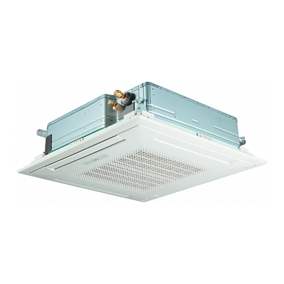
SPLIT TYPE
AIR CONDITIONER
CASSETTE
Models
Indoor unit
AUY36FUAS
AUY36UUAS
CONTENTS
SPECIFICATIONS . . . . . . . . . . . . . . . . . . . . . . . . . . . . . 1
DIMENSIONS . . . . . . . . . . . . . . . . . . . . . . . . . . . . . . . . 3
REFRIGERANT SYSTEM DIAGRAM . . . . . . . . . . . . . 5
CIRCUIT DIAGRAM . . . . . . . . . . . . . . . . . . . . . . . . . . . 6
INDOOR PCB CIRCUIT DIAGRAM . . . . . . . . . . . . . .
ERROR CONTENTS . . . . . . . . . . . . . . . . . . . . . . . . . .
DISASSEMBLY ILLUSTRATION . . . . . . . . . . . . . . . . . 12
PARTS LIST . . . . . . . . . . . . . . . . . . . . . . . . . . . . . . . . 22
STANDARD ACCESSORIES . . . . . . . . . . . . . . . . . . . 24
type (50Hz)
Outdoor unit
AOY36FNAXT
AOY36UNAXT
8
. . . . . . . . . . . 10
11
Advertisement
Table of Contents


Need help?
Do you have a question about the AUY36FUAS and is the answer not in the manual?
Questions and answers