Table of Contents
Advertisement
Advertisement
Table of Contents

Related Manuals for IVT AirModule E 15


Summary of Contents for IVT AirModule E 15
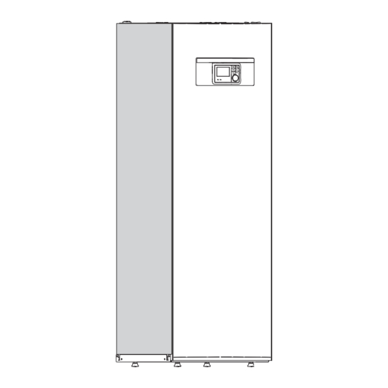
- Page 1 AirModule E 9/15 230V 1N~ / 400V 3N~ Installer Guide 6 720 813 268(2014/10)
-
Page 2: Table Of Contents
Table of Contents 8.12 Connection option EMS bus ......33 Table of Contents User interface ..........34 Product description . -
Page 3: Key To Symbols And Safety Instructions
Key to symbols and safety instructions General safety instructions Key to symbols and safety instructions These installation instructions are intended for plumbers, heating engineers and electricians. Key to symbols ▶ Read any installation instructions (heat pump, heating controls, etc.) carefully before starting the installation. Warnings ▶... -
Page 4: Standard Delivery
Standard delivery Standard delivery 6 720 810 350-01.1I Fig. 1 Standard delivery Heat pump module Application area Legs The heat pump module may only be used in closed heating systems in Operating Instructions accordance with EN 12828. Installation instructions Other usage is prohibited. Any damage resulting from prohibited usage Safety assembly in loose parts is excluded from liability. -
Page 5: Type Plate
General underfloor heating system circuit with mixing valve. A room controller is recommended, since the heat pump then will automatically adjust flow temperature. Only circuits with mixing valve To ensure that a sufficient amount of energy is available for defrosting, a buffer cylinder of at least 50L is required for heat pump sizes 5-9 and of at least 100L for heat pump sizes 13-17. -
Page 6: Technical Information
Technical information Technical information Technical information - heat pump module Unit Electrical information Power supply /230 Recommended fuse size / 50 Immersion heater in steps 3/6/9 3/6/9/12/15 Heating installation Connection Cu 28 Cu 28 Maximum operating pressure Minimum operating pressure Expansion vessel External available pressure Minimum flow... -
Page 7: System Configurations
Technical information System configurations Circulation pump PC1 is controlled by the control unit in the heat pump module. The heat pump and heat pump module may be installed If a fresh water station is installed, it must have its own control unit. only in accordance with the official system solutions If a buffer cylinder is used, a 3-way valve VC0 must be installed in provided by the manufacturer. - Page 8 Technical information 4.2.3 Heat pump with heat pump module system configuration Installermodul RTH2000 RTH2000 HCM2000 Rego 2000 400V AC 400 /230 V AC Airmodule E.. AirX .. 6 720 809 156-22.2I Fig. 3 Heat pump with heat pump module Installed in the heat pump module. Installed either in the heat pump module or mounted to the wall.
- Page 9 Technical information 4.2.4 Heat pump, heat pump module and buffer cylinder system configuration RTH2000 RTH2000 Installermodul Rego 2000 HCM2000 HCM2000 400V AC 400 /230 V AC BC 100/120 Airmodule E.. AirX .. 6 720 809 156-22.3I Fig. 4 Heat pump with heat pump module and buffer cylinder Installed in the heat pump module.
- Page 10 Technical information 4.2.5 General symbol explanation Symbol Designation Symbol Designation Symbol Designation Pipework/Wiring Flow - heating/solar circuit Electric wire Return - heating/solar circuit Potable water Electric wire disconnected DHW circulation Actuators/Valves/Temperature sensors/Pumps Valve Differential pressure regulator DHW circulation pump Revision bypass Pressure relief valve Non-return valve Adjustment valve...
-
Page 11: Measurements, Positioning Distance, And Pipe Connections
Measurements, positioning distance, and pipe connections Measurements, positioning distance, and pipe connections Heat pump module dimensions and connections _ > 6 720 810 350-09.1I Fig. 5 Heat pump module minimum distance There should be at least 50 mm between the heat pump module sides Fig. - Page 12 Measurements, positioning distance, and pipe connections <50V 230V 400V 6 720 809 156-08.2I Fig. 8 Heat pump module connections Heat transfer medium out (to the heat pump) Heat transfer medium in (from the heat pump) Cold water inlet connection DHW outlet connection Cable feed to IP module Cable bus CAN-BUS and sensor Return to solar thermal system (only on the solar models)
-
Page 13: Pipework
Regulations Assemble the safety assembly: ▶ Place the flow temperature sensor in the sensor pocket ([T0], figure 10), and secure the sensor with a cable tie. ▶ First install the particle filter ([SC1], figure 10) on the T-unit. ▶ Fit the safety assembly on the heat pump module. ▶... -
Page 14: Installation
Installation Maximum Deduct the figure Installation Size of Size of length of below from the Valve discharge discharge straight pipe maximum length for NOTICE: Risk of operating problems due to pipe outlet pipework pipework (no bends or each bend or elbow in contamination! size elbows) -
Page 15: Water Quality
Installation Water quality Heating system flushing Heat pumps operate with lower temperatures than other heating NOTICE: System damage due to objects in the pipes! systems, which means that the thermal degassing is not as effective and Objects in the pipes will decrease the flow and cause the oxygen content will never be as low as in an electric/oil/gas system. -
Page 16: Installation With Solar Heater (Only Solar Model)
Installation ▶ Turn off floor circuits in moist rooms (e.g. bathrooms and kitchens) and use relay outputs PK2 in order to govern this ( Chapter 8.4). Installation with solar heater (only solar model) Using solar additional heating requires installation of a solar module (accessory). -
Page 17: Connecting The Heat Pump Module To The Heat Pump
Installation 7.11 Connecting the heat pump module to the heat pump Insulate pipes and connections against condensation if cooling is to be ▶ Connect the return to the heat pump [4] to the heat transfer medium used. out [1] figure 13. ▶... -
Page 18: Connecting The Heat Pump Module To The Heating System And Tap Water
Installation 7.12 Connecting the heat pump module to the heating system and tap water Insulate the connections and pipes to the heating system from Pressure relief valve, non-return valve, and fill valve must condensation if cooling is used. be installed on the tap DHW circuit (not included). ▶... -
Page 19: Low Energy Pump For Heat Transfer Medium (Pc0)
Installation The heating system circulation pump is required and selected based on the system pressure drop and flow requirements. PC1 must always be connected to the installer module in the heat pump module according to the circuit diagram. Relay output max. load for circulation pump PC1: 2 A, cos>0.4. -
Page 20: Temperature Sensor Installation
Installation The dew point will vary depending on temperature and humidity. The higher the humidity, the higher flow temperature is required to remain above dew point and avoid condensation. The condensation sensors will send a signal to the operating system when they sense condensation and stop the cooling. - Page 21 Installation 6 720 809 156-23.1I Fig. 17 Outside temperature sensor positioning AirModule –6 720 813 268(2014/10)
-
Page 22: Heat Pump And Heat Pump Module Filling
Installation 7.20 Heat pump and heat pump module filling When filled, the system has to be thoroughly vented. ▶ Fill the system according to these instructions. ▶ Connect the system to power as described in Chapter 8. ▶ System commissioning as described in Chapter 11. ▶... -
Page 23: Electric Installation
Electric installation The heat pump and the heat pump module are connected by a Electric installation communications wire, CAN-BUS. A suitable cable for external cable installation is wire LIYCY (TP) DANGER: Risk of electric shock! 2x2x0.75, or equivalent. An alternative cable should have a cross The heat pump module components conduct electricity. -
Page 24: Printed Circuit Board Handling
Electric installation Printed circuit board handling 8.4.1 External outputs Circuit boards with control electronics are sensitive to discharges of NOTICE: Damage due to incorrect connection! static electricity (ESD – ElectroStatic Discharge) when handled. To Connections intended for a different voltage or current prevent damaging the components, special care is therefore required can damage electrical components. -
Page 25: Electric Box Layout
Electric installation Electric box layout 6 720 809 156-07.2I Fig. 22 Electric box layout Terminals Automatic fuses (only 15 kW model) Contactors K1, K2, K3 Overheating protection reset Installer module 8.7.1 Terminal connections in electric box 9 kW immersion heater 3N~, standard setting 6 720 809 156-16.3I Fig. - Page 26 Electric installation 8.7.2 Terminal connections in electric box 9 kW immersion heater 1N~, see bridge placement 6 720 809 156-32.1I Fig. 24 Terminal connections in electric box 230 V 1 N~ 50 A, input The heat pump has a separate power supply from the 230 V 1 N~, EMS Plus accessories distribution board 230 V 1 N~16 A.
- Page 27 Electric installation 8.7.4 Circuit diagram 9 kW immersion heater 3N~, standard setting 6 720 809 156-33.2I Fig. 26 Circuit diagram 9 kW 3N~ Distribution board Immersion heater L1-L2, heat pump L3. Immersion Heat pump module 9 kW, 400 V 3 N~ heater L3 blocked during heat pump mode.
- Page 28 Electric installation 8.7.6 Circuit diagram 15 kW immersion heater 3N~, standard setting 6 720 809 156-34.2I Fig. 28 Circuit diagram 15 kW 3N~ Distribution board Heat pump module 15 kW, 400 V 3 N~ Heat pump 13/17, 400 V 3 N~ [PC1] Heating system circulation pump [T0] Flow temperature sensor [T1] Outside temperature sensor...
-
Page 29: Power Supply Heat Pump And Heat Pump Module 9 Kw 3N
Electric installation Power supply heat pump and heat pump module 9 kW 3N~ 6 720 809 156-36.2I Fig. 29 Power supply heat pump and heat pump module 9 kW Connection on: L1-L2-L3-1N-PE. Input 400 V 3 N~ Feed heat pump: 2L3-2N-PE. User interface User interface: L-N-PE Immersion heater alarm output ([2] Fig. -
Page 30: Power Supply Heat Pump And Heat Pump Module 15 Kw
Electric installation Power supply heat pump and heat pump module 15 kW 6 720 809 156-38.2I Fig. 30 Power supply heat pump and heat pump module 15 kW [K1] Contactor step 1 [K2] Contactor step 2 Input 400 V 3 N~ [K3] Contactor step 3 User interface •... -
Page 31: Installer Module Circuit Diagram
Electric installation 8.10 Installer module circuit diagram Fig. 31 Installer module circuit diagram [I1] External input 1 [PC1] Heating system circulation pump [I2] External input 2 [PK2] Cooling season relay output 230 V [I3] External input 3 [PW2] Hot water DHW circulation pump [I4] External input 4 [VC0]... -
Page 32: Heat Pump/Heat Pump Module Circuit Diagram
Electric installation 8.11 Heat pump/heat pump module circuit diagram 6 720 810 350-10.1I Fig. 32 Heat pump/heat pump module circuit diagram Heat pump module Heat pump IP module Accessories (extra heating circuit, pool, sun, etc.) Room controller (accessories) User interface Addressing with 9 kW immersion heater (standard setting) Addressing with 15 kW immersion heater (standard setting) Delivered connected... -
Page 33: Connection Option Ems Bus
Electric installation 8.12 Connection option EMS bus 6 720 809 156-43.1I Fig. 33 Connection option EMS bus Star network or serial connection with external coupling box Star network Serial connection Installer module Accessory modules (for example: Room Controller, Mixing Valve Module, Solar Module) AirModule –6 720 813 268(2014/10) -
Page 34: User Interface
User interface • Room controller CR10H as a separate room controller, which User interface measures relative humidity (for heating/cooling circuits) • MM100: Module for heating and cooling circuits with mixing valve Product description • MP100: Module for heat pump heated pool •... -
Page 35: Basic Principles Of Operation
Basic principles of operation Basic principles of operation 10.1 Key and symbol overview If the display is turned off, it will turn on when a key is used and a function executed. Quickly press the selector to turn on the display. If you don't use any keys, the menu display will turn back off. -
Page 36: Display Symbols Overview
Basic principles of operation 10.2 Display symbols overview 6 720 811 136-01.1O Fig. 35 An example of what the standard display might look like in a system with several heating/cooling circuits Pos. Symbol Designation Explanation Temperature Shows current flow temperature (heat pump module temperature) –... -
Page 37: Using The Service Menu
Basic principles of operation 10.3 Using the service menu Confirm or ignore a change Confirm a change If the display is turned off, it will turn on when a key is ▶ Push the selector to activate the highlighted post or confirm used and a function executed. -
Page 38: Service Menu Overview
Commissioning 10.4 Service menu overview Menu Purpose of the menu Page Startup Start the configuration wizard and configure the system by checking/modifying the most important settings. 38 Configure the heat pump by checking/modifying the most important settings. Heat pump Set booster heater Configure the booster by checking/modifying the most important settings. -
Page 39: System Commissioning Via Configuration Wizard
Commissioning 11.2 System commissioning via configuration wizard When the configuration wizard has performed the system analysis, the Startup menu opens. These settings must be checked and if required The configuration wizard will automatically detect the BUS units modified, and confirmed. installed in the system. -
Page 40: Commissioning Other Settings
Commissioning 11.3 Commissioning other settings If some functions are not activated, and modules, units or components are not installed, the non relevant items are hidden, while other settings are selected. 11.3.1 Checklist: adjust settings according to customer requirements When commissioning a device, ensure the satisfaction of both parties, making sure that the heating system meets the customer's needs and will not give cause for complaints. -
Page 41: Service Menu
Service menu For information on how to use the service menu, see Chapter 10 starting Service menu on page 35. The user interface menu is automatically adjusted to the system. Some Standard settings are marked in bold in the column items are only displayed if they correspond with the system construction Setting range (... -
Page 42: Heat Pump Settings
Service menu DHW settings Hybrid system Fault displays DHW system Energy:price ratio Active faults DHW heat pump 1...2 Anti-seizing protection System alarm history Start time Heat source alarm history ON temperature Diagnosis System information OFF temperature Function test DHW reduced Enable function tests Maintenance ON temperature... -
Page 43: Booster Heater Settings
Service menu Menu Item Setting range Description Prim. heating pump mode Automatic The heat transfer pump operates when the compressor operates. When the compressor is turned off, the pump is too. The heat transfer pump operates continuously. Temp.diff. TC3/TC0 heating 3 ... 15 K Permitted temperature differential between the heat pump flow and return in heating mode (... -
Page 44: Settings For Heating/Cooling
Service menu 12.2.2 Immersion heater menu Immersion heater settings are selected in this menu. This menu is only displayed if an immersion heater has been set as an additional heat source in the General settings menu for the booster heater. Menu Item Setting range Description... - Page 45 Service menu Minimal outside temperature °C Aten – 2 Köpenhamn – 13 Paris – 10 0 Berlin – 15 Lissabon Prag – 16 – 10 – 1 – 1 Bryssel London Budapest – 12 Madrid – 4 Sevastopol – 12 Bukarest –...
- Page 46 Service menu 12.3.2 Circuit 1 to 4 menu Settings for each separate heating/cooling circuit are selected in this NOTICE: Risk of damaging the screed! menu. Here you can set the type of heating system installed for the ▶ If an underfloor heating system is used, the max. flow selected heating/cooling circuit.
- Page 47 Service menu Menu Item Setting range Description Heating switch-on delay 1 ... 4 ... 48 h Heating start delay Room temperature – 5 ... 2 ... 5 K If the measured room temperature is above the set room temperature by the value set here, the cooling changeover diff.
- Page 48 Service menu compensate for the heating system's increased heating output capacity point is 25 °C flow temperature. The heating curve end point must be set in higher temperatures. according to the heating system´s system temperature. This calculation takes into account the adjusted outside temperature Decisive to the course of the heating curve (slope/gradient) are the two and the room control temperature.
- Page 49 Service menu 6 720 809 156-30. 2I Fig. 41 Setting of The heating curve for radiators Left: increase with system temperature T and minimum outside temperature T 1,min Right: parallel offset with room temperature offset or desired temperature Outside temperature straight heating curve is described by two points: the base point (the Flow temperature heating curve starting point) and the end point.
- Page 50 Service menu • If the outside temperature exceeds the frost protection temperature limit by 1 K ( °C) and there is no heating requirement, the heating circuit pump will be shut off. • If the outside temperature is below the frost protection temperature limit, the heating circuit pump will be turned on.
- Page 51 Service menu Menu Item Setting range Description Activated Required drying program settings are displayed. The drying program is not active and the settings are not displayed (standard settings). Dwell time before start The floor plate screed drying program starts after set delay (selected heating circuits are disconnected No dwell time during the delay, the frost protection is active, standard setting: no delay, ...
-
Page 52: Dhw Settings
Service menu 12.4 DHW settings The DHW system is delivered activated. If the DHW system is activated, but there is no DHW system installed, the user interface will indicate an operating error. ▶ If there is no DHW system installed in the system, then the DHW system must be deactivated in the commissioning or DHW menu. -
Page 53: Pool Settings
Service menu 12.4.1 Thermal disinfection Execute thermal disinfection regularly to eliminate pathogens (e.g. legionella). Regulations might apply to larger DHW systems ( WARNING: Risk of scalding! e.g. Drinking water regulations and standards) for thermal disinfection. During thermal disinfection, the domestic hot water is •... -
Page 54: Diagnostics Menu
Service menu Menu Item Description Remember not to set the time for at least one hour after Active faults All the current operating errors are displayed here, by Thermal disinfection. The functions may otherwise order of severity. Here you can unlock blocking errors interfere with each other. -
Page 55: Troubleshooting
Troubleshooting 12.9.6 Calibration menu Troubleshooting Menu Item Description A system error is displayed on the user interface display. The cause can Room temp. sen. ▶ Place a suitable precision measuring instrument be an error in the user interface, in a component, in a module, the heat adj. - Page 56 Troubleshooting Cause or error description Test procedure/cause Solution A51 6021 Defect collector temperature Check configuration. The selected setting requires a collector Modify configuration. sensor sensor. Check the connecting cable between the solar module and the Establish a correct connection. collector sensor. Check the collector sensor according to the diagram.
-
Page 57: Heat Pump And Heat Pump Module Venting
Heat pump and heat pump module venting Heat pump and heat pump module venting 6 720 809 156-22.1I Fig. 49 Heat pump module and heating system 1. Connect the heat pump and heat pump module to the power. 2. Ensure that the circulation pump PC1 is running. 3. -
Page 58: Heat Pump Module Components Replacement
Heat pump module components replacement ▶ Fill to 2 bar unless stated otherwise. Heat pump module components replacement ▶ If there is a pressure drop: check the expansion vessel and heating system for leaks. 1. Disconnect the heat pump and heat pump module power. 2. -
Page 59: Environmental Protection
Environmental protection ▶ Check Primary flow temperature. (heat transfer medium out sensor TC3) and Return temperature (heat transfer medium in sensor TC0) in heating mode. The flow should have a higher temperature than the return. ▶ Calculate the differential by TC3 – TC0. ▶... - Page 60 Maintenance Temperature sensor measured values Heat pump module Temperature sensor in, or connected to, the heat pump module (T0, T1, TW1, TC0, TC1) contains measured values according to fig. 43 and 44. °C °C °C °C 12488 5331 2490...
-
Page 61: Connection For Ip Module
Use of all the functions requires an internet connection and a router with an available RJ45 output. This may incur additional costs. Managing the installation from a cell phone requires the free app IVT Anywhere. 6 720 809 156-41.1I Fig. 53 IP module... -
Page 62: Commissioning Protocol
Commissioning protocol Commissioning protocol Commissioning date: Surname, Given name: Customer address: Address: City: Telephone: Installation company: Surname, Given name: Street address: City: Telephone: Product information: Product model: TTNR: Serial number: FD-no.: Installation components: Receipt/value Yes | No Room controller ... - Page 63 Commissioning protocol Power supply connection: Yes | No Is the phase order L1, L2, L3, N and PE in the heat pump and heat pump module correct? Yes | No Has the power been connected according to the installation instructions? Heat pump and booster heater fuse, trip characteristics? Manual mode: ...
- Page 64 Alto Energy Limited Unit 17 Glenmore Business Centre Witney, Oxfordshire, OX29 0AA, United Kingdom www.altoenergy.co.uk | info@altoenergy.co.uk...
Need help?
Do you have a question about the AirModule E 15 and is the answer not in the manual?
Questions and answers