
Subscribe to Our Youtube Channel
Related Manuals for IVT AirX Series


Summary of Contents for IVT AirX Series
- Page 1 AirX, AirModule E 9/15, Airbox E/S 230V 1N~ / 400V 3N~ 6 720 809 065-00.1I Operating Instructions 6 720 810 266 (2014/10)
-
Page 2: Table Of Contents
Table of Contents Table of Contents Key to symbols and safety instructions Key to symbols Key to symbols and safety instructions ....2 Warnings Key to symbols . -
Page 3: General Safety Instructions
General General safety instructions General These operating instructions are intended for the user of the heating Cooling is disabled in the UK model to comply with system. the regulations for RHI. ▶ Read any operating instructions (heat pump, heating controls, etc.) carefully before operation and keep them. -
Page 4: System Overview
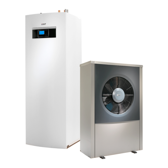
System overview decrease in speed when demand is low. This decreases energy System overview consumption. When the heating demand is higher during cold outdoor temperatures, The heating system consists of two parts: the heat pump, which is an additional heat source - a booster - may be required. This booster installed outdoors, and the heat pump module with or without integrated heater is either integrated or external, an its on/off is controlled by the hot water cylinder, which is installed indoors (AirModule and Airbox E). - Page 5 System overview AirModule heat pump module contains a hot water cylinder. Switching between heating and DHW is managed by an internal 3-way valve. The integrated Heat pump AirX connected to heat pump module AirModule provides a booster in the heat pump module will turn on if needed. complete installation for both heating and domestic hot water, since the Fig.
-
Page 6: Overview Of The Most Common Functions
Overview of the most common functions Overview of the most common functions In the user interface operating instructions you will find a complete description of all functions and settings. menu info 6 720 808 471-01.1O Fig. 4 Keys Pos. Designation Explanation Favourites key ▶... -
Page 7: Changing The Room Temperature
Overview of the most common functions Changing the room temperature Operation Results If some day you are cold or feel it is too hot: temporarily change the room temperature Change the room temperature until the next switching time ▶ Turn the selector to set desired room temperature. The corresponding time slot is displayed in grey in the time program bar chart. -
Page 8: Selecting A Heating Circuit For The Standard Display
Overview of the most common functions Selecting a heating circuit for the standard display determine which heating circuit the data in the standard display relates The standard display only ever shows data for a single heating circuit. If two or more heating circuits are installed, a setting can be made to Operation Results ▶... -
Page 9: Maintenance
Maintenance Checking the safety valves Maintenance The safety valve should be checked by a qualified The heat pump requires a minimum of maintenance, however, some engineer - usually as part of an annual service visit. servicing is still required to get optimal performance from your heat pump. -
Page 10: Pressure Switch And Overheat Protection
Maintenance Pressure Switch and Overheat protection Pressure switch and overheat protection are only in heat pump module with integrated electrical supplement. Overheat protection must be manually reset if it trips. The pressure switch and overheat protection are connected in series, triggered alarm or information in the controll unit means either low pressure in the system or to high temperature in the additional heater. - Page 11 Maintenance 6 720 810 156-10.1I Fig. 7 AirModule Reset overheating protection Particle filter Pressure gauge AirX, AirModule E 9/15, Airbox E/S – 6 720 810 266 (2014/10)
-
Page 12: Cleaning The Condensate Pan
Maintenance Cleaning the condensate pan If the user interface shows an alarm indicating that the heat pump cover requires cleaning, the condensate pan should be cleared of dirt and leaves, which inhibit defrosting. Warning: The thin aluminum fins of the evaporator are sharp and delicate and can be damaged by negligence. -
Page 13: Connection For Ip-Module
Managing the installation from a all of equal importance to us and all environmental protection legislation cell phone requires the free app IVT Anywhere. and regulations are strictly observed. We use the best possible technology and materials for protecting the Commissioning environment taking account of economic considerations. - Page 14 Technical glossary Technical glossary Heat pump Cooling circuit Cooling is disabled in the UK model to comply with The central heat source. Placed outdoors, also referred to as an outside the regulations for RHI. unit. Contains the cooling circuit. Waterborne heating or cooling is transferred from the heat pump to the heat pump module.
- Page 15 Technical glossary Child lock The standard display settings and in the menu can only be modified if the child lock (key lock) has been disabled ( page 8). Mixing device Assembly that automatically ensures that hot water can be drawn from the taps at a temperature no higher than the temperature set on the mixer.
- Page 16 Alto Energy Limited Unit 17 Glenmore Business Centre Witney, Oxfordshire OX29 0AA United Kingdom www.altoenergy.co.uk | support@altoenergy.co.uk...
Need help?
Do you have a question about the AirX Series and is the answer not in the manual?
Questions and answers
Unit will not restart after 48hrs power cut. It is stuck at 18* flow for the past hour. Outdoor **** not running. Briefly showed fault code A01 5272 but this is gone now. Any ideas how to restart it. Airbox E/S 400v 3N
To troubleshoot and restart an IVT Series unit stuck at 18°C flow after a power cut and showing fault code A01 5272, follow these steps:
1. Check terminal 64 on the installer module: Alarm 5272 is triggered if 230V is detected here. This involves the external additional heater/overheating protector.
2. Possible causes and actions:
- Tripped fuse at the distribution box: Replace or reset the fuse.
- See causes for alarm 5246: Investigate related alarms that may provide more context for 5272.
3. Check pressure and overheat protection:
- If the overheat protection tripped, manually reset it.
- Check the pressure gauge:
- If below 0.5 bar, slowly fill the system to a maximum of 2 bar.
4. Restart the system: After resolving the issue, restart the unit.
5. If unsure: Contact the installer or retailer for assistance.
This answer is automatically generated