Table of Contents
Advertisement
Quick Links
Download this manual
See also:
Operator's Manual
Advertisement
Table of Contents

Subscribe to Our Youtube Channel
Related Manuals for CAB MAESTRO 4S


Summary of Contents for CAB MAESTRO 4S
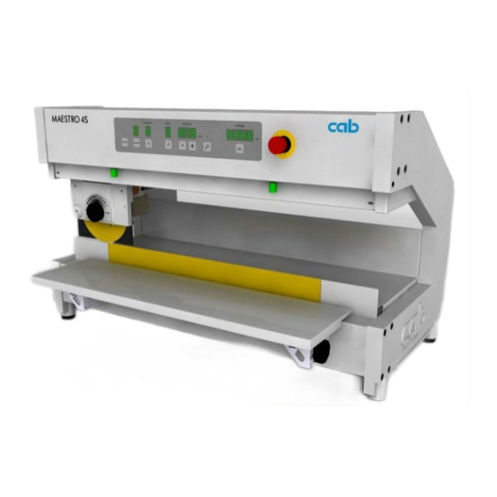
- Page 1 Service Manual PCB Separator MAESTRO 4S...
- Page 2 Edition: 09/2016 Art.-Nr.: 9009826 Copyright This documentation as well as translation hereof are property of cab Produkttechnik GmbH & Co. KG. The replication, conversion, duplication or divulgement of the whole manual or parts of it for other intentions than its original intended purpose demand the previous written authorization by cab.
-
Page 3: Table Of Contents
Contents Introduction ............................4 Instructions ............................... 4 Intended Use ............................4 Safety Instructions ............................ 5 Technical Data ............................6 Overview ..............................7 Views without covers and cable ....................... 7 Tools ................................. 8 Contents of Delivery ..........................8 Test and Change Device Parts ......................9 Changing the Upper Blade ........................ -
Page 4: Introduction
Introduction Instructions Important information and instructions in this documentation are designated as follows: Danger! Draws your attention to an exceptionally grave, impending danger to your health or life. Warning! Indicates a hazardous situation that could lead to injuries or material damage. Attention! Draws attention to possible dangers, material damage or loss of quality. - Page 5 Introduction • Only connect the device to other devices which have a protective low voltage. • Switch off all affected devices (e.g. conveyor belt) before connecting or unlinking. • Risk of hand injury. Wear protective gloves while PCB separating. • Ensure that people‘s clothing, hair, jewelry etc.
-
Page 6: Technical Data
Technical Data Technical data 4S/450 4S/600 Separation type Component side: circular blade Soldering side: linear blade Operation motorized and optimized Separation speedt 300/500 mm/sec. switchable Material FR4, Aluminium Height of components Component side/Soldering side up to 34 mm Cutting length , continuous F up to 450 mm up to 600 mm Length D... -
Page 7: Overview
Overview Views without covers and cable Fig.1 Frontview Fig.2 Rearview 1 Belt Gear Main Motor 9 Control Panel 2 Pulse Sensor 10 Emergency Switch 3 Carriage Sensor right / Links 11 tension Wheel 4 Carriage 12 Linear Blade 5 Set knob for cutting depth 13 PCB Control 6 Upper Circular Blade 14 Main Motor... -
Page 8: Tools
Only use tools and testing devices that are suitable for the task at hand. Special tools (cab production): • Dial gauge assembly (cab part No. 8970208) to check the blade position Commercial tools: • Allen key 1,5, 2,0, 2,5, 5,0 mm •... -
Page 9: Test And Change Device Parts
Test and Change Device Parts Changing the Upper Blade In case of wasting, damage or material modified it's necessary to change the upper blade. Video Video: MAESTRO 4S - Changing the upper blade on www.cab.de Risk of hand injury ! Wear protective gloves while changing the blade. Danger! Risk of cutting damage by rotating blade! Unlink device before you start service work! 1. -
Page 10: Adjustment Of The Upper Blade Stopper
Test and Change Device Parts Adjustment of the Upper Blade Stopper Notice! The lower stop of the upper blade adjustment is already adjusted by delivery. After a long operation time, while working at strongly varying temperatures or else after replacing a blade, it is recommended to re-adjust the lower stop. -
Page 11: Changing The Linear Blade
Test and Change Device Parts Changing the Linear Blade Video Video: MAESTRO 4S - Changing the linear blade on www.cab.de Warning! Risk of cutting injury in handling of the linear blade. Risk of hand injury ! Wear protective gloves while changing the blade. -
Page 12: Check The Blade Alignment
Test and Change Device Parts Attention! Decouple the carriage before move the carrige by hand . Damage the electronics! Fig.8 Setting of the linear blade (Front view) Fig.9 Setting of the linear blade (Rear view) 1. Decouple the carriage (1) from motor by the lever (3). 2. -
Page 13: Changing The Hub To Main Motor
Test and Change Device Parts Changing the hub to main motor Danger! Danger to life and limb from power supply. Befor open the device unlink the power! rear view Fig.11 Dismount the hub to the main motor 1. Swing lever (13) in position b to connect the blade with the motor and to relax spring (8) . 2. -
Page 14: Changing The Control Panel / Emergency Switch
Test and Change Device Parts Changing the Control Panel / Emergency Switch Danger! Danger to life and limb from power supply. Befor open the device unlink the power! 1. Dismount front and rear cover. „Changing the hub to main motor“ on page 13 2. -
Page 15: Changing The Energy Track
Mounting the energy track (7) in reverse order. 4.10 Check the Sensors Some sensors are integrated into the Maestro 4S to control the function and operation of the device. This are reflex sensors with a switch reaction in case a surface are in front of approx. 3mm distance. For changing and adjusting is a 5,5 mm jaw wrench necessary. -
Page 16: Check The Sensors Via Control Panel
Bauteilwechsel und Prüfen Test and Change Device Parts 4.10.1 Prüfen der Sensoren am Bedienfeld 4.10.1 Check the Sensors via Control Panel Bild 16 Bedienfeld Gelb Pantone 123C, Grün RAL 6018, Blau Pantone 7461, Grau Pantone 422C, Beschriftung, Fenster- und LED-Umrandung Schwarz, Fenster- und LED-Fond Filtergrau. 29.10.2013 Lortz Fig.16 Gelb Pantone 123C,... -
Page 17: Check The Sensors On Pcb
Test and Change Device Parts 4.10.2 Check the Sensors on PCB Some sensors are integrated into the Maestro 4S to control the function and operation of the device. This are reflex sensors with a switch reaction in case a surface are in front of approx. 3mm distance. For changing and adjusting is a 5,5 mm jaw wrench necessary. - Page 18 Test and Change Device Parts It will measured with a Oscilloscope in a measurement range of 1 or 5 Volt per scale devision. cut length Fig.20 Measurement by Oscilloscope Pulse sensor Carriage sensor right Carriage sensor left Edge sensor right Edge sensor left ----------------------- -----------------------...
-
Page 19: Errors
Errors Cause of error Effect / Display Error recovery Switch of the device and switch it on The food-switch is clear in the not ready moment of synchronization step again. Display blink distance Display New synchronization The device is switched on and the cut length Display carriage with the upper blade will... -
Page 20: Spare Parts Drawings
Spare Parts Drawings Side Parts C Profile, Linear Blade Part No. Description Note Serial No. Part No. Description Note Serial No. from from 5902082.001 Screw DIN912-M6x30 17.1 8933394.001 Linear Blade 8936866.001 C Profile 17.2 8933682.001 Linear Blade 8930823.001 Bracket 5902122.001 Screw DIN923-M6x6 5905141.001 Foot 8930886.001 Comb 8930946.001 Bushing... -
Page 21: Main Motor
Spare Parts Drawings Main Motor Part No. Description Note Serial No. Part No. Description Note Serial No. from from 5902082.001 Screw DIN912-M6x30 8930915.001 Edge Sensor 5903520.001 Washer DIN7349-4.3 50.1 8936858.001 Beam 5903010.001 Spring Washer DIN137-A6 50.2 8936898.001 Beam 8930988.001 Bearing Plate 8936871.001 Bolt 4374 5902014.001 Screw DIN912-M4x14... -
Page 22: Upper Beam, Control Panel
Spare Parts Drawings Upper Beam, Control Panel Part No. Description Note Serial No. from 5903527.001 Snap Ring DIN471-10x1 5903005.001 Washer DIN9021-4.3 5902022.001 Screw DIN7985-M4x10 5903004.001 Washer DIN125-A3.2 58.1 8936822.001 Cover 58.2 8936862.001 Cover 5902026.001 Screw DIN7985-M3x6 8930981.001 Cable Grounding 8936871.001 Bolt 8936870.001 Control Panel 8930868.001 Tightener 8930854.001 Tensioning Wheel... -
Page 23: Power Supply
Spare Parts Drawings Power Supply Part No. Description Note Serial No. from 5902241.001 Screw DIN7984-M4x10 8936896.001 Bushing 57.1 8936846.001 Energy Track 57.2 8936847.001 Energy Track 8930981.001 Cable Grounding 5902358.001 Screw DIN7984-M4x6 5551126.001 Power Supply 5902510.001 Nut DIN934-M4 5903033.001 Washer DIN125-A4.3 5903011.001 Toothed Washer DIN6797-A4.3 5534176.001 Cable Grounding 5902047.001 Screw DIN7991-M3x5... -
Page 24: Carriage With Roller Blade
Spare Parts Drawings Carriage With Roller Blade Part No. Description Note Serial No. Part No. Description Note Serial No. from from 105.1 8931628.001 Set Knob 4504 5902241.001 Screw DIN7984-M4x10 105.2 8936943.001 Set Knob 4505 5902245.001 Screw DIN933-M3x10 106.1 8931627.001 Guide Washer 4504 5903004.001 Washer DIN125-A3.2 106.2 8936945.001 Guide Washer...
Need help?
Do you have a question about the MAESTRO 4S and is the answer not in the manual?
Questions and answers