
Related Manuals for ASROCK Z370 Taichi


Summary of Contents for ASROCK Z370 Taichi
-
Page 1: User Manual
Z370 Professional Gaming i7 User Manual Version 1.0 Published December 2016 Copyright©2016 ASRock INC. All rights reserved. -
Page 2: Copyright Notice
(including damages for loss of profits, loss of business, loss of data, interruption of business and the like), even if ASRock has been advised of the possibility of such damages arising from any defect or error in the documentation or product. - Page 3 You are also entitled to have the goods repaired or replaced if the goods fail to be of acceptable quality and the failure does not amount to a major failure. If you require assistance please call ASRock Tel : +886-2-28965588 ext.123 (Standard International call charges apply) The terms HDMI™...
-
Page 4: Table Of Contents
Chapter 1 Introduction Package Contents Specifications Motherboard Layout I/O Panel WiFi-802.11ac Module and ASRock WiFi 2.4/5 GHz Antenna Chapter 2 Installation Installing the CPU Installing the CPU Fan and Heatsink Installing Memory Modules (DIMM) Expansion Slots (PCI and PCI Express Slots) - Page 5 Chapter 3 Software and Utilities Operation Installing Drivers A-Tuning ASRock Live Update & APP Shop 3.3.1 UI Overview 3.3.2 Apps 3.3.3 BIOS & Drivers 3.3.4 Setting ASRock RGB LED Chapter 4 UEFI SETUP UTILITY Introduction EZ Mode Advanced Mode 4.3.1 UEFI Menu Bar 4.3.2 Navigation Keys...
- Page 6 4.6.7 USB Configuration 4.6.8 Trusted Computing Tools Hardware Health Event Monitoring Screen Security Screen 4.10 Boot Screen 4.11 Exit Screen...
-
Page 7: Chapter 1 Introduction
If you require technical support related to this mother- board, please visit our website for specific information about the model you are using. You may find the latest VGA cards and CPU support list on ASRock’s website as well. ASRock website http://www.asrock.com. -
Page 8: Specifications
• Supports DDR4 4333+(OC)*/4266(OC)/4133(OC)/4000(OC) /3866(OC)/3800(OC)/3733(OC)/3600(OC)/3200(OC)/2933 (OC)/2800(OC)/2666/2400/2133 non-ECC, un-buffered memory * Please refer to Memory Support List on ASRock's website for more information. (http://www.asrock.com/) Gen Intel® CPU supports DDR4 up to 2666. • Supports ECC UDIMM memory modules (operate in non- ECC mode) • Max. - Page 9 Z370 Taichi • 15μ Gold Contact in VGA PCIe Slot (PCIE2) Graphics • Intel® UHD Graphics Built-in Visuals and the VGA outputs can be supported only with processors which are GPU integrated. • Supports Intel® UHD Graphics Built-in Visuals : Intel®...
- Page 10 - Pure Power-In - Direct Drive Technology - PCB Isolate Shielding - Impedance Sensing on Front Out port - Individual PCB Layers for R/L Audio Channel - Gold Audio Jacks - 15μ Gold Audio Connector • Supports DTS Connect • Gigabit LAN 10/100/1000 Mb/s • 1 x Giga PHY Intel®...
- Page 11 ** Type 22110 M.2 module is supported with either M2_1 or M2_2 socket. ** Supports Intel® Optane Technology ** Supports NVMe SSD as boot disks ** Supports ASRock U.2 Kit Connector • 1 x TPM Header • 1 x Power LED and Speaker Header • 1 x RGB LED Header * Supports in total up to 12V/3A, 36W LED Strip • 1 x CPU Fan Connector (4-pin)
- Page 12 * The Chassis Optional/Water Pump Fan supports the water cooler fan of maximum 1.5A (18W) fan power. * CPU_OPT/W_PUMP, CHA_FAN1, CHA_FAN2 and CHA_ FAN3/W_PUMP can auto detect if 3-pin or 4-pin fan is in use. • 1 x 24 pin ATX Power Connector (Hi-Density Power Connector) • 1 x 8 pin 12V Power Connector (Hi-Density Power Connector)
- Page 13 • ErP/EuP ready (ErP/EuP ready power supply is required) * For detailed product information, please visit our website: http://www.asrock.com Please realize that there is a certain risk involved with overclocking, including adjusting the setting in the BIOS, applying Untied Overclocking Technology, or using third-party overclocking tools.
-
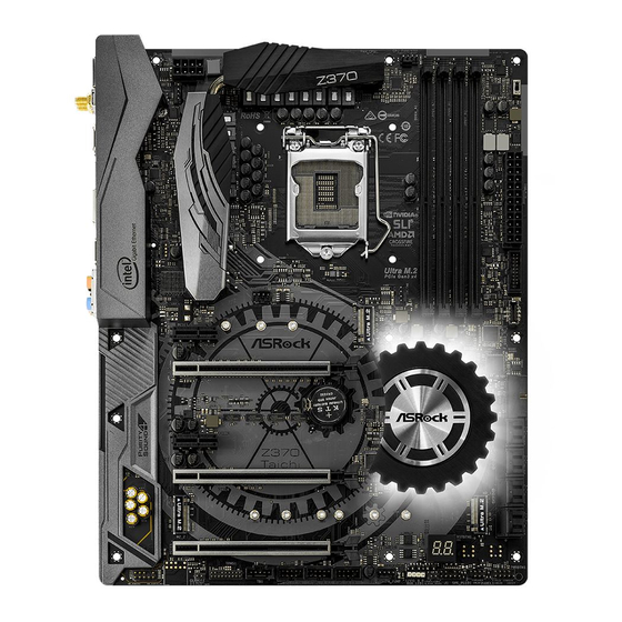
Page 14: Motherboard Layout
1.3 Motherboard Layout CPU_FAN1 CLRBTN1 ATX12V1 CPU_OPT/ W_PUMP RoHS M2_WIFI_1 RJ-45 (I219V) USB 3.1 Gen2 Top: T: USB31_TA_1 RJ-45 B: USB31_TC_1 (I211AT) USB 3.1 Gen1 T: USB3 B: USB4 Ultra M.2 PCIe Gen3 x4 CHA_FAN2 F_USB31_TC_2 CHA_FAN1 PCIE1 PCIE2 CMOS Intel Battery Z370... - Page 15 Z370 Taichi No. Description ATX 12V Power Connector (ATX12V1) CPU Fan / Waterpump Fan Connector (CPU_OPT/W_PUMP) Chassis Fan Connector (CHA_FAN1) CPU Fan Connector (CPU_FAN1) 2 x 288-pin DDR4 DIMM Slots (DDR4_A1, DDR4_B1) 2 x 288-pin DDR4 DIMM Slots (DDR4_A2, DDR4_B2)
-
Page 16: I/O Panel
1.4 I/O Panel No. Description No. Description PS/2 Mouse/Keyboard Port USB 3.1 Gen1 Ports (USB_3_4) DisplayPort 1.2 USB 3.1 Gen2 Type-A Port (USB31_TA_1) LAN RJ-45 Port (Intel® I211AT)* USB 3.1 Gen2 Type-C Port (USB31_TC_1) Central / Bass (Orange) LAN RJ-45 Port (Intel® I219V)* Rear Speaker (Black) HDMI Port Line In (Light Blue) - Page 17 Z370 Taichi ** If you use a 2-channel speaker, please connect the speaker’s plug into “Front Speaker Jack”. See the table below for connection details in accordance with the type of speaker you use. Audio Output Front Speaker Rear Speaker...
-
Page 18: Wifi-802.11Ac Module And Asrock Wifi 2.4/5 Ghz Antenna
1.5 WiFi-802.11ac Module and ASRock WiFi 2.4/5 GHz Antenna WiFi-802.11ac + BT Module This motherboard comes with an exclusive WiFi 802.11 a/b/g/n/ac + BT v4.2 module (pre-installed on the rear I/O panel) that offers support for WiFi 802.11 a/b/ g/n/ac connectivity standards and Bluetooth v4.2. WiFi + BT module is an easy-to- use wireless local area network (WLAN) adapter to support WiFi + BT. -
Page 19: Installation
Z370 Taichi WiFi Antennas Installation Guide Step 1 Prepare the WiFi 2.4/5 GHz Antennas that come with the package. Step 2 Connect the two WiFi 2.4/5 GHz Antennas to the antenna connectors. Turn the antenna clock- wise until it is securely connected. -
Page 20: Chapter 2 Installation
Chapter 2 Installation This is an ATX form factor motherboard. Before you install the motherboard, study the configuration of your chassis to ensure that the motherboard fits into it. Pre-installation Precautions Take note of the following precautions before you install motherboard components or change any motherboard settings. -
Page 21: Installing The Cpu
Z370 Taichi 2.1 Installing the CPU 1. Before you insert the 1151-Pin CPU into the socket, please check if the PnP cap is on the socket, if the CPU surface is unclean, or if there are any bent pins in the socket. Do not force to insert the CPU into the socket if above situation is found. - Page 23 Z370 Taichi Please save and replace the cover if the processor is removed. The cover must be placed if you wish to return the motherboard for after service.
-
Page 24: Installing The Cpu Fan And Heatsink
2.2 Installing the CPU Fan and Heatsink... -
Page 25: Installing Memory Modules (Dimm)
Z370 Taichi 2.3 Installing Memory Modules (DIMM) This motherboard provides four 288-pin DDR4 (Double Data Rate 4) DIMM slots, and supports Dual Channel Memory Technology. 1. For dual channel configuration, you always need to install identical (the same brand, speed, size and chip-type) DDR4 DIMM pairs. -
Page 27: Expansion Slots (Pci And Pci Express Slots)
Z370 Taichi 2.4 Expansion Slots (PCI and PCI Express Slots) There are 5 PCI Express slots on the motherboard. Before installing an expansion card, please make sure that the power supply is switched off or the power cord is unplugged. Please read the documentation of the expansion card and make necessary hardware settings for the card before you start the installation. -
Page 28: Jumpers Setup
2.5 Jumpers Setup The illustration shows how jumpers are setup. When the jumper cap is placed on the pins, the jumper is “Short”. If no jumper cap is placed on the pins, the jumper is “Open”. Clear CMOS Jumper Short: Clear CMOS (CLRCMOS1) Open: Default 2-pin Jumper... -
Page 29: Onboard Headers And Connectors
Z370 Taichi 2.6 Onboard Headers and Connectors Onboard headers and connectors are NOT jumpers. Do NOT place jumper caps over these headers and connectors. Placing jumper caps over the headers and connectors will cause permanent damage to the motherboard. System Panel Header... - Page 30 Power LED and Speaker Please connect the SPEAKER DUMMY Header chassis power LED and DUMMY (7-pin SPK_PLED1) the chassis speaker to this (see p.8, No. 18) header. PLED+ PLED+ PLED- Serial ATA3 Connectors These eight SATA3 (SATA3_0_1: connectors support SATA see p.8, No.
- Page 31 Z370 Taichi USB 2.0 Headers There are three USB USB_PWR (9-pin USB_9_10) 2.0 headers on this DUMMY (see p.8, No. 24) motherboard. Each USB (9-pin USB_11_12) 2.0 header can support (see p.8, No. 23) two ports. USB_PWR (9-pin USB_13_14) (see p.8, No. 22) USB 3.1 Gen1 Headers...
-
Page 32: Fan Connector
1. High Definition Audio supports Jack Sensing, but the panel wire on the chassis must support HDA to function correctly. Please follow the instructions in our manual and chassis manual to install your system. 2. If you use an AC’97 audio panel, please install it to the front panel audio header by the steps below: A. - Page 33 Z370 Taichi CPU Optional/Water This motherboard FAN_SPEED_CONTROL Pump Fan Connector provides a 4-Pin water CPU_FAN_SPEED FAN_VOLTAGE (4-pin CPU_OPT/W_ cooling CPU fan PUMP) connector. If you plan (see p.8, No. 2) to connect a 3-Pin CPU water cooler fan, please connect it to Pin 1-3.
- Page 34 RGB LED Header RGB header is used to connect (4-pin RGB_LED1) RGB LED extension cable which 12V G R (see p.8, No. 20) allows users to choose from various LED lighting effects. Caution: Never install the RGB LED cable in the wrong orientation;...
-
Page 35: Smart Switches
Z370 Taichi 2.7 Smart Switches The motherboard has two smart switches: Clear CMOS Button and XMP Switch, allowing users to clear the CMOS values or load XMP profiles. Clear CMOS Button Clear CMOS Button (see p.10, No. 17) allows users to quickly clear the CMOS values. -
Page 36: Dr. Debug
2.8 Dr. Debug Dr. Debug is used to provide code information, which makes troubleshooting even easier. Please see the diagrams below for reading the Dr. Debug codes. Code Description Please check if the CPU is installed correctly and then clear CMOS. - Page 37 Z370 Taichi Problem related to USB devices. Please try removing all USB devices. Problem related to memory. Please re-install the CPU and memory then clear CMOS. If the problem still exists, please install only one memory module or try using other memory modules.
-
Page 38: Sli Tm And Quad Sli Tm Operation Guide
2.9 SLI and Quad SLI Operation Guide ® This motherboard supports NVIDIA and Quad SLI (Scalable Link Interface) technology that allows you to install up to two identical PCI Express x16 graphics cards. Requirements ® 1. You should only use identical SLI -ready graphics cards that are NVIDIA certified. - Page 39 Z370 Taichi Step 3 Align and insert the ASRock SLI_HB_ Bridge_2S Card to the goldfingers on each graphics card. Make sure the ASRock SLI_ HB_Bridge_2S Card is firmly in place. SLI_HB_Bridge_2S Car d ASRock SLI_HB_Bridge_2S Card Step 4 Connect a VGA cable or a DVI cable to the...
-
Page 40: Driver Installation And Setup
2.9.2 Driver Installation and Setup Install the graphics card drivers to your system. After that, you can enable the ® Multi-Graphics Processing Unit (GPU) in the NVIDIA nView system tray utility. Please follow the below procedures to enable the multi-GPU. For SLI and Quad SLI mode... -
Page 41: Tm And Quad Crossfirex
Z370 Taichi 2.10 CrossFireX , 3-Way CrossFireX and Quad CrossFireX Operation Guide This motherboard supports CrossFireX , 3-way CrossFireX and Quad CrossFireX that allows you to install up to three identical PCI Express x16 graphics cards. 1. You should only use identical CrossFireX -ready graphics cards that are AMD certified. - Page 42 Step 3 Connect a VGA cable or a DVI cable to the monitor connector or the DVI connec- tor of the graphics card that is inserted to PCIE2 slot.
-
Page 43: Installing Three Crossfirex
Z370 Taichi 2.10.2 Installing Three CrossFireX -Ready Graphics Cards Step 1 Insert one graphics card into PCIE2 slot, another graphics card to PCIE4 slot, and the other graphics card to PCIE5 slot. Make sure that the cards are properly seated on the slots. -
Page 44: Driver Installation And Setup
2.10.3 Driver Installation and Setup Step 1 Power on your computer and boot into OS. Step 2 Remove the AMD drivers if you have any VGA drivers installed in your system. The Catalyst Uninstaller is an optional download. We recommend using this utility to un- install any previously installed Catalyst drivers prior to installation. - Page 45 Z370 Taichi 2.11 M.2_SSD (NGFF) Module Installation Guide (M2_3) The M.2, also known as the Next Generation Form Factor (NGFF), is a small size and versatile card edge connector that aims to replace mPCIe and mSATA. The Ultra M.2 Socket (M2_3) supports SATA3 6.0 Gb/s module and M.2 PCI Express module up to Gen3 x4 (32 Gb/s).
- Page 46 Step 3 Move the standoff based on the module type and length. The standoff is placed at the nut location D by default. Skip Step 3 and 4 and go straight to Step 5 if you are going to use the default nut. Otherwise, release the standoff by hand.
- Page 47 Z370 Taichi M.2_SSD (NGFF) Module Support List Vendor Interface ADATA SATA3 AXNS381E-128GM-B ADATA SATA3 AXNS381E-256GM-B ADATA SATA3 ASU800NS38-256GT-C ADATA SATA3 ASU800NS38-512GT-C ADATA PCIe3 x4 ASX7000NP-128GT-C ADATA PCIe3 x4 ASX8000NP-256GM-C ADATA PCIe3 x4 ASX7000NP-256GT-C ADATA PCIe3 x4 ASX8000NP-512GM-C ADATA PCIe3 x4...
- Page 48 SATA3 VLM100-120G-2280B-RD V-Color SATA3 VLM100-240G-2280RGB V-Color SATA3 VSM100-240G-2280 V-Color SATA3 VLM100-240G-2280B-RD SATA3 WDS100T1B0B-00AS40 SATA3 WDS240G1G0B-00RC30 PCIe3 x4 WDS256G1X0C-00ENX0 (NVME) PCIe3 x4 WDS512G1X0C-00ENX0 (NVME) For the latest updates of M.2_SSD (NFGG) module support list, please visit our website for details: http://www.asrock.com...
- Page 49 Z370 Taichi 2.12 M.2_SSD (NGFF) Module Installation Guide (M2_1 and M2_2) The M.2, also known as the Next Generation Form Factor (NGFF), is a small size and versatile card edge connector that aims to replace mPCIe and mSATA. The Ultra M.2 Sockets (M2_1 and M2_2) support SATA3 6.0 Gb/s module and M.2 PCI Express module...
- Page 50 Step 3 Move the standoff based on the module type and length. The standoff is placed at the nut location D by default. Skip Step 3 and 4 and go straight to Step 5 if you are going to use the default nut. Otherwise, release the standoff by hand.
- Page 51 Z370 Taichi M.2_SSD (NGFF) Module Support List Vendor Interface ADATA SATA3 AXNS381E-128GM-B ADATA SATA3 AXNS381E-256GM-B ADATA SATA3 ASU800NS38-256GT-C ADATA SATA3 ASU800NS38-512GT-C ADATA PCIe3 x4 ASX7000NP-128GT-C ADATA PCIe3 x4 ASX8000NP-256GM-C ADATA PCIe3 x4 ASX7000NP-256GT-C ADATA PCIe3 x4 ASX8000NP-512GM-C ADATA PCIe3 x4...
- Page 52 SATA3 VLM100-120G-2280B-RD V-Color SATA3 VLM100-240G-2280RGB V-Color SATA3 VSM100-240G-2280 V-Color SATA3 VLM100-240G-2280B-RD SATA3 WDS100T1B0B-00AS40 SATA3 WDS240G1G0B-00RC30 PCIe3 x4 WDS256G1X0C-00ENX0 (NVME) PCIe3 x4 WDS512G1X0C-00ENX0 (NVME) For the latest updates of M.2_SSD (NFGG) module support list, please visit our website for details: http://www.asrock.com...
-
Page 53: Chapter 3 Software And Utilities Operation
Z370 Taichi Chapter 3 Software and Utilities Operation 3.1 Installing Drivers The Support CD that comes with the motherboard contains necessary drivers and useful utilities that enhance the motherboard’s features. Running The Support CD To begin using the support CD, insert the CD into your CD-ROM drive. The CD automatically displays the Main Menu if “AUTORUN”... -
Page 54: A-Tuning
3.2 A-Tuning A-Tuning is ASRock’s multi purpose software suite with a new interface, more new features and improved utilities. 3.2.1 Installing A-Tuning A-Tuning can be downloaded from ASRock Live Update & APP Shop. After the installation, you will find the icon “A-Tuning“ on your desktop. Double-click the “A-Tuning“... -
Page 55: System Info
Z370 Taichi OC Tweaker Configurations for overclocking the system. System Info View information about the system. *The System Browser tab may not appear for certain models. - Page 56 Configure up to five different fan speeds using the graph. The fans will automatically shift to the next speed level when the assigned temperature is met. Settings Configure ASRock A-Tuning. Click to select "Auto run at Windows Startup" if you want A-Tuning to be launched when you start up the Windows operating system.
-
Page 57: Asrock Live Update & App Shop
Double-click on your desktop to access ASRock Live Update & APP Shop utility. *You need to be connected to the Internet to download apps from the ASRock Live Update & APP Shop. 3.3.1 UI Overview Category Panel Hot News... -
Page 58: Apps
3.3.2 Apps When the "Apps" tab is selected, you will see all the available apps on screen for you to download. Installing an App Step 1 Find the app you want to install. The most recommended app appears on the left side of the screen. The other various apps are shown on the right. - Page 59 Z370 Taichi Step 3 If you want to install the app, click on the red icon to start downloading. Step 4 When installation completes, you can find the green "Installed" icon appears on the upper right corner. To uninstall it, simply click on the trash can icon...
- Page 60 Upgrading an App You can only upgrade the apps you have already installed. When there is an available new version for your app, you will find the mark of "New Version" appears below the installed app icon. Step 1 Click on the app icon to see more details. Step 2 Click on the yellow icon to start upgrading.
-
Page 61: Bios & Drivers
Z370 Taichi 3.3.3 BIOS & Drivers Installing BIOS or Drivers When the "BIOS & Drivers" tab is selected, you will see a list of recommended or critical updates for the BIOS or drivers. Please update them all soon. Step 1 Please check the item information before update. -
Page 62: Setting
3.3.4 Setting In the "Setting" page, you can change the language, select the server location, and determine if you want to automatically run the ASRock Live Update & APP Shop on Windows startup. -
Page 63: Asrock Rgb Led
Z370 Taichi 3.4 ASRock RGB LED ASRock RGB LED is a lighting control utility specifically designed for unique individuals with sophisticated tastes to build their own stylish colorful lighting system. Simply by connecting the LED strip, you can customize various lighting schemes and patterns, including Static, Breathing, Strobe, Cycling, Music, Wave and more. - Page 64 ASRock RGB LED Utility Now you can adjust the RGB LED color through the ASRock RGB LED utility. Download this utility from the ASRock Live Update & APP Shop and start coloring your PC style your way! Drag the tab to customize your preference.
-
Page 65: Chapter 4 Uefi Setup Utility
Z370 Taichi Chapter 4 UEFI SETUP UTILITY 4.1 Introduction This section explains how to use the UEFI SETUP UTILITY to configure your system. You may run the UEFI SETUP UTILITY by pressing <F2> or <Del> right after you power on the computer, otherwise, the Power-On-Self-Test (POST) will continue with its test routines. -
Page 66: Ez Mode
4.2 EZ Mode The EZ Mode screen appears when you enter the BIOS setup program by default. EZ mode is a dashboard which contains multiple readings of the system’s current status. You can check the most crucial information of your system, such as CPU speed, DRAM frequency, SATA information, fan speed, etc. -
Page 67: Advanced Mode
Z370 Taichi 4.3 Advanced Mode The Advanced Mode provides more options to configure the BIOS settings. Refer to the following sections for the detailed configurations. To access the EZ Mode, press <F6> or click the "EZ Mode" button at the upper right corner of the screen. -
Page 68: Navigation Keys
4.3.2 Navigation Keys Use < > key or < > key to choose among the selections on the menu bar, and use < > key or < > key to move the cursor up or down to select items, then press <Enter>... -
Page 69: Main Screen
Z370 Taichi 4.4 Main Screen When you enter the UEFI SETUP UTILITY, the Main screen will appear and display the system overview. My Favorite Display your collection of BIOS items. Press F5 to add/remove your favorite items. -
Page 70: Oc Tweaker Screen
4.5 OC Tweaker Screen In the OC Tweaker screen, you can set up overclocking features. Because the UEFI software is constantly being updated, the following UEFI setup screens and descriptions are for reference purpose only, and they may not exactly match what you see on your screen. - Page 71 Z370 Taichi CPU Configuration Multi Core Enhancement Improve the system's performance by forcing the CPU to perform the highest frequency on all CPU cores simultaneously. Disable to reduce power consumption . CPU Ratio The CPU speed is determined by the CPU Ratio multiplied with the BCLK.
-
Page 72: Long Duration Power Limit
handoff. Max Battery mode will set CPU ratio as x8 till OS handoff. This option is suggested for BCLK overclocking. Reliability Stress Restrictor Disable or Enable Reliability Stress Restrictor feature. FCLK Frequency Configure the FCLK Frequency. AVX Ratio Offset AVX Ratio Offset specifies a negative offset from the CPU Ratio for AVX workloads. AVX is a more stressful workload that lowers the AVX ratio to ensure maximum possible ratio for SSE workloads. -
Page 73: Long Duration Maintained
Z370 Taichi Long Duration Maintained Configure the period of time until the CPU ratio is lowered when the Long Duration Power Limit is exceeded. Short Duration Power Limit Configure Package Power Limit 2 in watts. When the limit is exceeded, the CPU ratio will be lowered immediately. -
Page 74: Dram Frequency
DRAM Frequency If [Auto] is selected, the motherboard will detect the memory module(s) inserted and assign the appropriate frequency automatically. Primary Timing CAS# Latency (tCL) The time between sending a column address to the memory and the beginning of the data in response. - Page 75 Z370 Taichi Write to Read Delay (tWTR_L) The number of clocks between the last valid write operation and the next read command to the same internal bank. Write to Read Delay (tWTR_S) The number of clocks between the last valid write operation and the next read command to the same internal bank.
- Page 76 tRDWR_dg Configure between module read to write delay. tRDWR_dr Configure between module read to write delay. tRDWR_dd Configure between module read to write delay. tWRRD_sg Configure between module write to read delay. tWRRD_dg Configure between module write to read delay. tWRRD_dr Configure between module write to read delay.
-
Page 77: Advanced Setting
Z370 Taichi RTL (CH A) Configure round trip latency for channel A. RTL (CH B) Configure round trip latency for channel B. IO-L (CH A) Configure IO latency for channel A. IO-L (CH B) Configure IO latency for channel B. -
Page 78: Voltage Configuration
ODT NOM (CH B) Use this to change ODT (CH B) Auto/Manual settings. The default is [Auto]. Dll Bandwidth 0 Configure the Dll Bandwidth 0. Dll Bandwidth 1 Configure the Dll Bandwidth 1. Dll Bandwidth 2 Configure the Dll Bandwidth 2. Dll Bandwidth 3 Configure the Dll Bandwidth 3. - Page 79 Z370 Taichi GT Core/Cache Voltage Configure the voltage for the CPU Core/Cache. GT Load-Line Calibration GPU Load-Line Calibration helps prevent GPU voltage droop when the system is under heavy load. DRAM Voltage Use this to configure DRAM Voltage. The default value is [Auto].
- Page 80 CLK VDD Voltage Configure the voltage for the CLK VDD. DMI Voltage Configure the voltage for the DMI. CPU Internal PLL Voltage Default is 0.900V. Each step is 0.015V. Adding 9- 15 steps will helps CPU PLL to lock internal clock during High frequency under Ln2 cooling. For example: 1.020V - 1.125V will be proper value.
- Page 81 Z370 Taichi Load User Default Load previously saved user defaults. Save User UEFI Setup Profile to Disk Save current UEFI settings as an user default profile to disk. Load User UEFI Setup Profile to Disk Load previously saved user defaults from the disk.
-
Page 82: Advanced Screen
4.6 Advanced Screen In this section, you may set the configurations for the following items: CPU Configuration, Chipset Configuration, Storage Configuration, Intel(R) Thunder- bolt, Super IO Configuration, ACPI Configuration, USB Configuration and Trusted Computing. Setting wrong values in this section may cause the system to malfunction. UEFI Configuration UEFI Setup Style Select the default mode when entering the UEFI setup utility. -
Page 83: Cpu Configuration
Z370 Taichi 4.6.1 CPU Configuration Intel Hyper Threading Technology Intel Hyper Threading Technology allows multiple threads to run on each core, so that the overall performance on threaded software is improved. Active Processor Cores Select the number of cores to enable in each processor package. -
Page 84: Intel Virtualization Technology
CPU C7 State Support Enable C7 sleep state for lower power consumption. Package C State Support Enable CPU, PCIe, Memory, Graphics C State Support for power saving. CFG Lock This item allows you to disable or enable the CFG Lock. CPU Thermal Throttling Enable CPU internal thermal control mechanisms to keep the CPU from overheat- ing. -
Page 85: Chipset Configuration
Z370 Taichi 4.6.2 Chipset Configuration Primary Graphics Adapter Select a primary VGA. Top of Lower Usable Dram Set the maximum value of TOLUD. Set this item to Dynamic to allow TOLUD to adjust automatically based on the largest MMIO length of the installed graphic controller. - Page 86 PCIE3 Link Speed Select the link speed for PCIE3. PCIE4 Link Speed Select the link speed for PCIE4. PCIE5 Link Speed Select the link speed for PCIE5. PCI Express Native Control Select Enable for enhanced PCI Express power saving in OS. PCIE ASPM Support This option enables/disables the ASPM support for all CPU downstream devices.
-
Page 87: Front Panel
Z370 Taichi Inte(R) Ethernet Controller I211 Enable or disable the onboard network interface controller (Intel® I211AT). Onboard HD Audio Enable/disable onboard HD audio. Set to Auto to enable onboard HD audio and automatically disable it when a sound card is installed. -
Page 88: Storage Configuration
4.6.3 Storage Configuration SATA Controller(s) Enable/disable the SATA controllers. SATA Controller Speed Indicates the maximum speed the SATA controller can support. SATA Mode Selection [AHCI] Supports new features that improve performance. [Intel RST Premium (RAID)] Combine multiple disk drives into a logical unit. SATA Aggressive Link Power Management SATA Aggressive Link Power Management allows SATA devices to enter a low power state during periods of inactivity to save power. - Page 89 Z370 Taichi Third Party SATA 3 Controller Enable or disable the third party SATA3 controller.
-
Page 90: Intel® Thunderbolt
4.6.4 Intel® Thunderbolt Intel® Thunderbolt Technology Enable or disable the Intel® Thunderbolt™ function. Security Level Allows you to choose a security level for the Thunderbolt ports. AR AIC Support Enable or disable to support AR AIC card. TBT Host Router Enable the host router based on ports available. -
Page 91: Super Io Configuration
Z370 Taichi 4.6.5 Super IO Configuration PS2 Y-Cable Enable the PS2 Y-Cable or set this option to Auto. -
Page 92: Acpi Configuration
4.6.6 ACPI Configuration Suspend to RAM Select disable for ACPI suspend type S1. It is recommended to select auto for ACPI S3 power saving. ACPI HEPT Table Enable the High Precision Event Timer for better performance. PS/2 Keyboard Power On Allow the system to be waked up by a PS/2 Keyboard. -
Page 93: Usb Configuration
Z370 Taichi 4.6.7 USB Configuration Legacy USB Support Enable or disable Legacy OS Support for USB 2.0 devices. If you encounter USB compatibility issues it is recommended to disable legacy USB support. Select UEFI Setup Only to support USB devices under the UEFI setup and Windows/Linux operating systems only. -
Page 94: Trusted Computing
4.6.8 Trusted Computing Security Device Support Enable or disable BIOS support for security device. -
Page 95: Tools
RGB LED and header allows users to connect LED strip and create their unique PC style easily. UEFI Tech Service Contact ASRock Tech Service if you are having trouble with your PC. Please setup network configuration before using UEFI Tech Service. Easy RAID Installer Easy RAID Installer helps you to copy the RAID driver from the support CD to your USB storage device. - Page 96 Save UEFI files in your USB storage device and run Instant Flash to update your UEFI. Internet Flash - DHCP (Auto IP), Auto ASRock Internet Flash downloads and updates the latest UEFI firmware version from our servers for you. Please setup network configuration before using Internet Flash.
-
Page 97: Network Configuration
Z370 Taichi Secure Backup UEFI Whenever one of the ROM images are outdated or corrupted, switch to the other flash ROM and execute Secure Backup UEFI to duplicate the current working ROM image to the secondary flash ROM. This motherboard has two BIOS chips, an active BIOS (BIOS_A) and a backup BIOS (BIOS_B), which enhances the safety and stability of your system. -
Page 98: Hardware Health Event Monitoring Screen
4.8 Hardware Health Event Monitoring Screen This section allows you to monitor the status of the hardware on your system, including the parameters of the CPU temperature, motherboard temperature, fan speed and voltage. Fan Tuning Measure Fan Min Duty Cycle. Fan-Tastic Tuning Select a fan mode for CPU Fans 1&2, or choose Customize to set 5 CPU temperatures and assign a respective fan speed for each temperature. - Page 99 Z370 Taichi CPU_OPT / W _ Pump Switch Select CPU Optional or Water Pump mode. CPU Optional Fan Control Mode Select PWM mode or DC mode for CPU Optional fan. CPU Optional Fan Setting Select a fan mode for CPU Optional fan, or choose Customize to set 5 CPU temperatures and assign a respective fan speed for each temperature.
- Page 100 Chassis Fan 2 Step Up Set the value of Chassis Fan 2 Step Up. Chassis Fan 2 Step Down Set the value of Chassis Fan 2 Step Down. CHA_FAN3 / W _ Pump Switch Select CHA_FAN3/CPU Optional or Water Pump mode. Chassis Fan 3 Control Mode Select PWM mode or DC mode for Chassis Fan 3.
-
Page 101: Security Screen
Z370 Taichi 4.9 Security Screen In this section you may set or change the supervisor/user password for the system. You may also clear the user password. Supervisor Password Set or change the password for the administrator account. Only the administrator has authority to change the settings in the UEFI Setup Utility. -
Page 102: Boot Screen
4.10 Boot Screen This section displays the available devices on your system for you to configure the boot settings and the boot priority. Fast Boot Fast Boot minimizes your computer's boot time. In fast mode you may not boot from an USB storage device. The VBIOS must support UEFI GOP if you are using an external graphics card. - Page 103 Z370 Taichi Full Screen Logo Enable to display the boot logo or disable to show normal POST messages. AddOn ROM Display Enable AddOn ROM Display to see the AddOn ROM messages or configure the AddOn ROM if you've enabled Full Screen Logo. Disable for faster boot speed.
- Page 104 Launch Storage OpROM Policy Select UEFI only to run those that support UEFI option ROM only. Select Legacy only to run those that support legacy option ROM only. Select Do not launch to not execute both legacy and UEFI option ROM. Launch Video OpROM Policy Select UEFI only to run those that support UEFI option ROM only.
-
Page 105: Exit Screen
Z370 Taichi 4.11 Exit Screen Save Changes and Exit When you select this option the following message, “Save configuration changes and exit setup?” will pop out. Select [OK] to save changes and exit the UEFI SETUP UTILITY. Discard Changes and Exit When you select this option the following message, “Discard changes and exit... -
Page 106: Contact Information
Contact Information If you need to contact ASRock or want to know more about ASRock, you’re welcome to visit ASRock’s website at http://www.asrock.com; or you may contact your dealer for further information. For technical questions, please submit a support request form at https://event.asrock.com/tsd.asp... -
Page 107: Declaration Of Conformity
13848 Magnolia Ave, Chino, CA91710 Phone/Fax No: +1-909-590-8308/+1-909-590-1026 hereby declares that the product Product Name : Motherboard Z370 Taichi Model Number : Conforms to the following speci cations: FCC Part 15, Subpart B, Unintentional Radiators Supplementary Information: is device complies with part 15 of the FCC Rules. Operation is subject to the... - Page 108 EU Declaration of Conformity For the following equipment: Motherboard (Product Name) Z370 Taichi / ASRock (Model Designation / Trade Name) ASRock Incorporation (Manufacturer Name) 2F., No.37, Sec. 2, Jhongyang S. Rd., Beitou District, Taipei City 112, Taiwan (R.O.C.) (Manufacturer Address) EMC —Directive 2014/30/EU (from April 20th, 2016)
Need help?
Do you have a question about the Z370 Taichi and is the answer not in the manual?
Questions and answers