Table of Contents
Advertisement
Quick Links
Advertisement
Table of Contents

Related Manuals for EESiFlo Portalok 7S


Summary of Contents for EESiFlo Portalok 7S
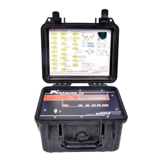
- Page 1 User Manual PORTALOK_7SV4-5-1EN Portable Ultrasonic Flowmeter Portalok 7S...
- Page 2 Portable Ultrasonic Flowmeter Portalok 7S PORTALOK_7SV4-5-1EN, 2014-09-01...
-
Page 3: Table Of Contents
Installation of the Transmitter Portalok 7S ........ - Page 4 Portalok 7S Table of Contents Displaying the Measured Values ............35 10.1...
- Page 5 Table of Contents Portalok 7S Troubleshooting ..............73 17.1...
- Page 6 Portalok 7S Table of Contents PORTALOK_7SV4-5-1EN, 2014-09-01...
-
Page 7: Introduction
Warranty The Portalok 7S measuring instrument is guaranteed for the term and to the conditions specified in the sales contract pro- vided the equipment has been used for the purpose for which it has been designed and operated according to the instruc- tions given in this User Manual. -
Page 8: Handling
General Precautions Portalok 7S is a precise measuring instrument and has to be handled with care. To obtain good measurement results and not damage the measuring instrument, it is important that great attention is paid to the instructions given in this user man- ual, particularly to the following points: •... -
Page 9: General Principles
3 General Principles Portalok 7S General Principles For the ultrasonic measurement of the flow rate, the flow velocity of the medium flowing in a pipe is determined. Further physical quantities (e.g., volumetric flow rate, mass flow rate) are derived from the flow velocity and from additional physi- cal quantities, if necessary. - Page 10 Portalok 7S 3 General Principles Flow velocity v The average value of the flow velocities over the cross-sectional pipe area. Acoustic calibration factor k /sin α α The acoustic calibration factor k is a parameter of the transducer which results from the sound speed c within the trans- ducer and the angle of incidence (see Fig.
- Page 11 3 General Principles Portalok 7S transducer (emitter) transducer (receiver) reduction in distance in the transducer α α α pipe wall β β γ flow direction γ of the medium sound path without flow sound path with flow Fig. 3.2: Sound path of the signal in the flow direction...
-
Page 12: Measurement Arrangements
Portalok 7S 3 General Principles Measurement Arrangements 3.3.1 Terms and Definitions Diagonal arrangement The transducers are mounted on the opposite sides of the pipe (see Fig. 3.5). Reflection arrangement The transducers are mounted on the same side of the pipe (see Fig. 3.6). - Page 13 3 General Principles Portalok 7S 3.3.2 Examples Diagonal arrangement Reflection arrangement 1 transducer pair 1 transducer pair 1 sound path 2 sound paths PORTALOK_7SV4-5-1EN, 2014-09-01...
-
Page 14: Description Of The Transmitter
RS232 interface output power supply transducer Fig. 4.1: Connections and command panel of the transmitter Portalok 7S 2x 16-digit LCD display, state indicator backlit "BATTERY" keyboard state indicator "CHARGING"... -
Page 15: Keyboard
4 Description of the Transmitter Portalok 7S Keyboard 4 Description of the Transmitter The keyboard consists of 5 keys. Tab. 4.1: General functions switching the transmitter on/off, switching the backlight on/off Press key PWR briefly to switch on the transmitter or to switch on/off the backlight when the transmitter is on. -
Page 16: Selection Of The Measuring Point
Selection of the Measuring Point Attention! Portalok 7S is must not be used in explosive atmospheres. If the measuring point is within a poten- tially explosive atmosphere, the danger zone and gases that may be present have to be determined. - Page 17 5 Selection of the Measuring Point Portalok 7S Tab. 5.1: Recommended transducer position Horizontal pipe Select a measuring point where the transducers can be mounted on the side of the pipe, allowing the sound waves to propagate in the pipe horizontally. Thus, solid at the bottom or gas bubbles at the top of the pipe will not influence the propagation of the signal.
-
Page 18: Undisturbed Flow Profile
Portalok 7S 5 Selection of the Measuring Point Undisturbed Flow Profile Some flow elements (elbows, slide valves, valves, control valves, pumps, reducers, diffusers, etc.) distort the flow profile in their vicinity. The axisymmetrical flow profile needed for correct measurement is no longer given. A careful selection of the measuring point helps to reduce the impact of disturbance sources. - Page 19 5 Selection of the Measuring Point Portalok 7S Tab. 5.2: Recommended distance from disturbance sources D = nominal pipe diameter at the measuring point, l = recommended distance disturbance source: T piece supply line: l ≥ 50 D return line: l ≥ 10 D disturbance source: diffuser supply line: l ≥...
-
Page 20: Selection Of The Measurement Arrangement Taking Onto Account The Measuring Range And The Measuring Conditions
Portalok 7S 5 Selection of the Measuring Point Tab. 5.2: Recommended distance from disturbance sources D = nominal pipe diameter at the measuring point, l = recommended distance disturbance source: pump supply line: l ≥ 50 D Selection of the Measurement Arrangement Taking onto Account the Measuring... -
Page 21: Selection Of The Sound Plane Near An Elbow
5 Selection of the Measuring Point Portalok 7S Selection of the Sound Plane Near an Elbow On vertical pipes On horizontal pipes flow direction elbow plane elbow plane flow direction • The sound beam plane (see section 3.3) has an angle •... -
Page 22: Installation Of The Transmitter Portalok 7S
• storing temperature: 12...25 °C (54...77 °F) State of the battery The transmitter Portalok 7S has 2 LEDs which indicate the state of the battery. The state indicator "BATTERY" • is off when the battery is charged to > 50 % •... -
Page 23: Connection Of The Output
6 Installation of the Transmitter Portalok 7S Portalok 7S Connection of the Output For the connection of the output see Fig. 4.1, Fig. 6.1, Tab. 6.1 and Tab. 6.2. Tab. 6.1: Circuits of the outputs output transmitter external circuit remark... -
Page 24: Installation Of The Transducers
Portalok 7S 7 Installation of the Transducers Installation of the Transducers Preparation of the Pipe • The pipe has to be stable. It has to be able to withstand the pressure exerted by the transducer mounting fixture. Rust, paint or other deposits on the pipe absorb the sound signal. A good acoustic contact between the pipe and the trans- ducers is obtained as follows: •... -
Page 25: Start-Up Of The Transmitter
During an initialization (INIT) of the transmitter, the settings in the program branches Parameter and Output Options and some of the settings in the program branch Special Funct. are reset to the default settings of EESiFlo. For INIT-resistant settings, see annex A. - Page 26 Portalok 7S 8 Start-up of the Transmitter 8.3.2 Program Branches • Program branch Parameter input of the pipe and medium parameters • Program branch Measuring processing of the steps for the measurement • Program branch Output Options setting of the physical quantity, the unit of measurement and the parameters for the measured value transmission •...
-
Page 27: Hotcodes
8 Start-up of the Transmitter Portalok 7S 8.3.3 Navigation A vertical arrow ↕ will be displayed if the menu item contains a scroll list. The current list item will be displayed in the lower line. Use key to select a list item in the lower line. Press ENTER. -
Page 28: Language Selection
When the last digit has been entered, the main menu will be displayed in the selected language. The selected language remains activated when the transmitter is switched off and on again. After an initialization, the de- fault language set by EESIFLo is activated. PORTALOK_7SV4-5-1EN, 2014-09-01... -
Page 29: Basic Measurement
9 Basic Measurement Portalok 7S Basic Measurement The pipe and medium parameters are entered for the selected measuring point (see chapter 5). The parameter ranges are limited by the technical characteristics of the transducers and of the transmitter. Note! During the parameter input, the transducers should be connected to the transmitter. -
Page 30: Input Of The Medium Parameters
Portalok 7S 9 Basic Measurement 9.1.4 Pipe Lining If the pipe has an inner lining, select yes. Press ENTER. Lining If no is selected, the next parameter will be displayed (see section 9.1.5). >YES< Select the lining material. Lining ↕... -
Page 31: Other Parameters
9 Basic Measurement Portalok 7S 9.2.1 Sound Speed The sound speed of the medium is used for the calculation of the transducer distance at the beginning of the measure- ment. However, the sound speed does affect the measuring result directly. Often, the exact value of the sound speed for a medium is unknown. -
Page 32: Defining The Measuring Point Number
Portalok 7S 9 Basic Measurement Defining the Measuring Point Number Select program branch Measuring. Press ENTER. par>MEA<opt sf Measuring If this error message is displayed, the parameters are not complete. Enter the missing pa- par>MEA<opt sf rameters in the program branch Parameter. - Page 33 9 Basic Measurement Portalok 7S 9 Basic Measurement 9.6.1 Fine Adjustment of the Transducer Distance If the displayed transducer distance is adjusted, press ENTER. Transd. Distance The measuring for the positioning of the transducers is started. mm ! The amplitude of the received signal is displayed by the bar graph S=.
-
Page 34: Start Of The Measurement
Portalok 7S 9 Basic Measurement 9.6.3 Value of the Sound Speed The sound speed of the medium can be displayed during the measurement by pressing key If an approximate range for the sound speed has been entered in the program branch Parameter and the transducer dis- tance has been optimized afterwards as described in section 9.6.2, it is recommended to write down the sound speed for... -
Page 35: Displaying The Measured Values
10 Displaying the Measured Values Portalok 7S Displaying the Measured Values The physical quantity is set in the program branch Output Options (see section 10.1). During the measurement, the designation of the physical quantity is displayed in the upper line, the measured value in the lower line. -
Page 36: Status Line
Portalok 7S 10 Displaying the Measured Values Press key during the measurement to change the display in the upper line, press key to change the display in the lower line. The character * indicates that the displayed value (here: flow velocity) is not the selected Flow Velocity physical quantity. -
Page 37: Transducer Distance
10 Displaying the Measured Values Portalok 7S 10.4 Transducer Distance By pressing key during the measurement, it is possible to scroll to the display of the L=(51.2) 50.8 mm transducer distance. 54.5 m3/h The optimum transducer distance (here: 51.2 mm) is displayed in parentheses in the upper line, followed by the entered transducer distance (here: 50.8 mm). -
Page 38: Advanced Measuring Functions
Portalok 7S 11 Advanced Measuring Functions Advanced Measuring Functions 11.1 Command Execution during Measurement Commands that can be executed during a measurement are displayed in the upper line. A command begins with the ar- row →. If programmed, a program code has to be entered first (see section 11.8). -
Page 39: Upper Limit Of The Flow Velocity
11 Advanced Measuring Functions Portalok 7S Selection of the totalizers for storing It is possible to store the totalizer for one flow direction or the totalizers for both flow directions. Select Special Funct.\SYSTEM settings\Storing\Quantity Storage. If one is selected, only the totalizer whose value is changing will be stored. This can apply Quantity Storage to the totalizer for the positive or the negative flow direction. -
Page 40: Cut-Off Flow
Portalok 7S 11 Advanced Measuring Functions 11.5 Cut-off Flow The cut-off flow is a lower limit for the flow velocity. All measured flow velocities that are lower than the limit and their de- rived values are set to zero. The cut-off flow can depend on the flow direction or not. The cut-off flow is set in Special Funct.\SYSTEM set- tings\Measuring\Cut-off Flow. -
Page 41: Change Of The Limit For The Inner Pipe Diameter
11 Advanced Measuring Functions Portalok 7S 11.7 Change of the Limit for the Inner Pipe Diameter It is possible to change the lower limit of the inner pipe diameter for a given transducer type. Enter HotCode 071001. Enter the lower limit of the inner pipe diameter of the displayed transducer type. Press EN- DNmin Q-Sensor TER to select the next transducer type. -
Page 42: Data Logger And Transmission Of Data
Portalok 7S 12 Data Logger and Transmission of Data Data Logger and Transmission of Data The transmitter has a data logger in which the measured values are stored during the measurement (see section 12.1). The measured values are transmitted to a PC via the serial interface directly during the measurement (see section 12.2). - Page 43 12 Data Logger and Transmission of Data Portalok 7S Start of the storing If it is necessary to synchronize the storing of measured values on several transmitters, the starting time of the storing can be set. Select the starting time of the storing of measured values.
- Page 44 Portalok 7S 12 Data Logger and Transmission of Data 12.1.4 Measurement with Activated Data Logger • Start the measurement. Enter the measuring point number. Press ENTER. Meas.Point No.: If arrows are displayed in the lower line on the right, ASCII text can be entered. If digits are xxx (↑↓←...
-
Page 45: Transmission Of Data
12 Data Logger and Transmission of Data Portalok 7S 12.2 Transmission of Data The measured values can be transmitted to a PC via the serial interface RS232. 12.2.1 Online Transmission of Data The measured values are transmitted during the measurement. If the data logger is activated, the measured values will also be stored. - Page 46 Portalok 7S 12 Data Logger and Transmission of Data Select yes to activate the online transmission of data. Serial Output >YES< • Set the storage rate (see section 12.1.2). • Start the measurement. The measuring point number will be requested (see section 12.1.4).
- Page 47 12 Data Logger and Transmission of Data Portalok 7S The line \DATA will be transmitted next. Afterwards the column titles will be transmitted (see Tab. 12.3) The measured val- ues are transmitted afterwards. Example: \DATA \*MEASURE; Q_POS; Q_NEG; In every storage interval, one data line is transmitted. The line "???" will be transmitted if there are no measured values available for the storage interval.
-
Page 48: Libraries
Portalok 7S 13 Libraries Libraries The internal material database of the transmitter contains parameters for pipe and lining materials as well as for media. It can be extended with user defined materials or media. User defined materials and media will always be displayed in the scroll lists of the program branch Parameter. -
Page 49: Input Of Material/Medium Parameters Without The Extended Library
13 Libraries Portalok 7S 13.1.1 Data Retention During the Partitioning of the Coefficient Memory When the coefficient memory is repartitioned, max. 8 data sets of each type can be retained. Example 1: The number of user defined materials is reduced from 5 to 3. The data sets #01 to #03 are retained. -
Page 50: Extended Library
If, however, the process conditions fluctuate strongly and the medium parameters depend strongly on the temperature (e.g., viscosity of a hydraulic oil), polynomials or customized interpolation functions should be used. Contact EESIFLo to find the best solution for the measuring task. - Page 51 13 Libraries Portalok 7S 13.3.2 Activation of the Extended Library Select Special Funct.\SYSTEM settings\Libraries\Extended Library. Extended Library Press ENTER. >ON< Select on to activate the extended library. Press ENTER. 13.3.3 Input of Material/Medium Parameters The parameters of a user defined material/medium can be entered now.
-
Page 52: Deleting A User Defined Material/Medium
Portalok 7S 13 Libraries Medium parameters Enter the medium's: • longitudinal sound speed • kinematic viscosity • density Depending on the selected function, 1...5 values have to be entered. Press ENTER after each input. If an already defined medium is edited, for each parameter of some of the functions there will be a request whether it is to be edited. - Page 53 13 Libraries Portalok 7S 13.5.1 Displaying a Scroll List Select Show list. Press ENTER to display the scroll list as in the program branch Pa- Material list ↕ rameter. >Show list The current scroll list is displayed in the lower line.
-
Page 54: Settings
Portalok 7S 14 Settings Settings 14.1 Time and Date The transmitter has a battery-powered clock. 14.1.1 Time Select Special Funct.\SYSTEM settings\Set Clock. Press ENTER. SYSTEM settings↕ Set Clock The current time is displayed. Select ok to confirm the time or new to set the time. Press... - Page 55 14 Settings Portalok 7S During the next scroll through the program branch Parameter, the outer pipe diameter Outer Diameter that corresponds to the entered pipe circumference will be displayed. 57.3 example: 180 mm : = 57.3 mm Note! The pipe circumference is only edited temporarily. When the transmitter switches back to the display of the pipe circumference (internal recalculation), slight rounding errors may occur.
-
Page 56: Measurement Settings
Portalok 7S 14 Settings Select bar or psi as the unit of measurement for the pressure. Press ENTER. Pressure >[bar]< [psi] Select yes if lb/ft3 is to be used as the unit of measurement for the density. Press EN- Density [lb/ft3] TER. -
Page 57: Setting The Contrast
14 Settings Portalok 7S Select on to keep the previous totalizer values after a restart of the measurement. Quantity recall Select off to reset the totalizers to zero after a restart of the measurement. >ON< Note! All changes will be stored at the end of the dialog. -
Page 58: Superuser Mode
Portalok 7S 15 SuperUser Mode SuperUser Mode The SuperUser mode offers the possibility of an advanced analysis of the signal and the measured values as well as the definition of additional parameters adapted to the measuring point, in order to achieve better measuring values or during experimental work. -
Page 59: Limit Of The Signal Amplification
15 SuperUser Mode Portalok 7S Example: profile bound for the laminar flow: 1 500 profile bound for the turbulent flow: 2 500 At Reynolds numbers < 1 500, the flow during the measurement is regarded as laminar for the calcu- lation of the physical quantity. -
Page 60: Upper Limit Of The Sound Speed
Portalok 7S 15 SuperUser Mode Select Special Funct.\SYSTEM settings\Measuring\Miscellaneous. Press ENTER until the menu item Gain threshold is displayed. Enter the max. signal amplification. Enter 0 (zero) if no limit of the signal amplification is to Gain threshold be used. -
Page 61: Number Of Decimal Places Of The Totalizers
15 SuperUser Mode Portalok 7S 15.6 Number of Decimal Places of the Totalizers The values of the totalizers can be displayed with up to 11 places, e.g., 74890046.03. In the SuperUser mode, it is pos- sible to define the number of decimal places. -
Page 62: Display Of The Sum Of The Totalizers
Portalok 7S 15 SuperUser Mode 15.8 Display of the Sum of the Totalizers The sum of the totalizers for the two flow directions can be displayed in the upper line during the measurement. Select Special Funct.\SYSTEM settings\Measuring\Miscellaneous. Press ENTER until the menu item Show Q is displayed. -
Page 63: Outputs
16 Outputs Portalok 7S Outputs The outputs have to be installed and activated before they can be used: • assign the physical quantity (source item) to be transmitted to the output and the properties of the signal • define the behavior of the output in case no valid measured values are available •... - Page 64 Portalok 7S 16 Outputs 16.1.1 Output Range During the configuration of an analog output, the output range is defined. Select a list item I1 Output range↕ or other range... to enter the output range manually. 4/20 mA If other range... has been selected, enter the values Output MIN and Output MAX.
- Page 65 16 Outputs Portalok 7S Tab. 16.3: Examples for the error output list item for the error output output signal I [ m A ] Error-value ↕ Minimum (4.0mA) Error-value ↕ I [ m A ] Hold last value Error-value ↕...
-
Page 66: Error Value Delay
Portalok 7S 16 Outputs 16.1.3 Function Test The function of the installed output can now be tested. Connect a multimeter with the installed output. Test of the analog output The current output is tested in the display. Enter a test value. It has to be within the output I1:Output Test range. -
Page 67: Activation Of The Current Output
16 Outputs Portalok 7S 16.3 Activation of the Current Output Note! An output can only be activated in the program branch Output Options if it has previously been in- stalled. Select the program branch Output Options. Press ENTER until Current Loop is dis- Current Loop played. -
Page 68: Activation Of A Binary Output As An Alarm Output
Portalok 7S 16 Outputs Enter the pulse value. The unit of measurement will be displayed according to the current Pulse Value physical quantity. 0.01 When the totalized physical quantity reaches the pulse value, a pulse will be emitted. Enter the pulse width. - Page 69 16 Outputs Portalok 7S 16.5.2 Setting the Limits If the switching condition MAX or MIN is selected in the scroll list func, the limit of the output will have to be defined: Select in the scroll list Input the physical quantity to be used for the comparison. The fol- R1 Input: ↕...
-
Page 70: Behavior Of The Alarm Output
Portalok 7S 16 Outputs 16.5.3 Defining the Hysteresis A hysteresis can be defined for the alarm output R1 to prevent a constant triggering of the alarm due to small fluctuations of the measured values around the limit. The hysteresis is a symmetrical range around the limit. The alarm will be activated if the measured values exceed the up- per limit and deactivated if the measured values fall below the lower limit. - Page 71 16 Outputs Portalok 7S 16.6.4 Alarm Output During the Measurement An alarm output with switching condition MAX or MIN will be updated max. once per second to avoid humming (i.e. fluctua- tion of the measured values around the value of the switching condition).
- Page 72 Portalok 7S 16 Outputs Tab. 16.1: Pictograms for the alarm state indication current state func mode (switching condition) (holding behavior) (switching function) closed NON-HOLD NO Cont. open HOLD NC Cont. +→- -→+ QUANT. ERROR Example: R1 = 16.6.6 Deactivation of the Output If the programmed output is no longer required, it can be deactivated.
-
Page 73: Troubleshooting
Check if the battery is inserted and charged. Connect the power supply. If the power supply is ok, the transducers or an in- ternal component of the transmitter are defective. The transducers and the transmitter have to be sent to EESIFLo for re- pair. -
Page 74: Selection Of The Measuring Point
• If no exclamation mark "!" is displayed, a measurement at the selected measuring point is not possible. Loss of signal during the measurement • If the pipe had run empty: Was there no measuring signal afterwards? Contact EESIFLo. • Wait briefly until acoustic contact is reestablished. The measurement can be interrupted by a temporarily higher propor- tion of gas bubbles and solids in the medium. -
Page 75: Large Deviations Of The Measured Values
17 Troubleshooting Portalok 7S 17.5 Large Deviations of the Measured Values The entered sound speed of the medium is wrong A wrong sound speed can result in the ultrasonic signal that is reflected directly on the pipe wall being mistaken for the measuring signal that has passed through the medium. -
Page 76: A Menu Structure
Portalok 7S A Menu Structure Menu Structure INIT- resistant Program Branch Parameter main menu: selection of the program branch Parameter >PAR< mea opt sf Parameter input of the outer pipe diameter Outer Diameter 100.0 input of the pipe circumference Pipe Circumfer. - Page 77 A Menu Structure Portalok 7S INIT- resistant input of the range around the average sound speed of the medium c-Medium=1500m/s This display will only be indicated if Other Medium has been selected. range +-150m/s input of the kinematic viscosity of the medium Kinem.Viscosity...
- Page 78 Portalok 7S A Menu Structure INIT- resistant activation of the measured value transmission to a PC or a printer via the serial Serial Output interface >YES< selection of the storage rate for storing measured values in the data logger Storage Rate ↕...
- Page 79 A Menu Structure Portalok 7S INIT- resistant input of the upper limit of the physical quantity to be monitored High Limit: This display will only be indicated if Alarm Output has been activated and MAX -10.00 m3/h has been selected as the switching condition.
- Page 80 Portalok 7S A Menu Structure INIT- resistant display of the occupancy of the coefficient memory USER AREA: used confirmation of the selected partition Format NOW? >YES< the coefficient memory is being partitioned FORMATTING ... ... SYSTEM settings\Libraries\Extended Library selection of the displays for the activation of the extended library Libraries ↕...
- Page 81 A Menu Structure Portalok 7S INIT- resistant selection if the absolute pressure p or the relative pressure p is to be used Pressure absolut >ON< selection of the unit of measurement for the sound speed Soundspeed unit >[m/s]< [fps] selection if lb/ft...
- Page 82 Portalok 7S A Menu Structure INIT- resistant Input of the cut-off flow for the absolute value of the measured values Cut-off Flow range: 0...12.7 cm/s cm/s default: 2.5 cm/s This display will only be indicated if Cut-off Flow = absolut and Cut-off Flow = user has been selected.
- Page 83 A Menu Structure Portalok 7S INIT- resistant Input of the max. Reynolds number at which the flow is laminar. Laminar flow range: 0...25 500 (rounded to hundreds) if R*< 0: the default value 1 000 is used This display will only be indicated if the SuperUser mode is activated and Pro- file bounds = user is selected.
- Page 84 Portalok 7S A Menu Structure INIT- resistant activation of the storing of the signal amplitude Store Amplitude The value will only be stored if the data logger is activated. >ON< activation of the storing of the sound speed of the medium Store c-Medium The value will only be stored if the data logger is activated.
- Page 85 A Menu Structure Portalok 7S INIT- resistant display of the data transmission progress ....Delete Meas.Val. selection of the displays for the deleting of stored measured values Special Funct. ↕ Delete Meas.Val. confirmation for the deleting of measured values...
- Page 86 Portalok 7S A Menu Structure INIT- resistant input of the constants for the longitudinal sound speed of the material L-SOUNDSP. The number of constants depends on the function selected above. 1500.0 selection of the sound wave type for the flow measurement Default soundsp.
- Page 87 A Menu Structure Portalok 7S INIT- resistant input of a designation for the selected medium #2: Input Name: USER MEDIUM input of the constants for the longitudinal sound speed of the medium SOUNDSPEED The number of constants depends on the function selected above.
-
Page 88: B Units Of Measurement
Portalok 7S B Units of Measurement Units of Measurement Length/Roughness Temperature unit of measurement description unit of measurement description millimeter degree Celsius °C inch degree Fahrenheit inch °F Pressure unit of measurement description bar (absolute) bar(a) bar (relative) bar(g) pound per square inch (absolute) - Page 89 B Units of Measurement Portalok 7S Volumetric flow rate Volume (totalized) unit of measurement description unit of measurement cubic meter per day m3/d cubic meter per hour m3/h cubic meter per minute m3/min cubic meter per second m3/s 1000 cubic meters per hour...
- Page 90 Portalok 7S B Units of Measurement Mass flow rate Mass (totalized) unit of measurement description unit of measurement metric ton per hour metric ton per day kilogram per hour kg/h kilogram per minute kg/min kilogram per second kg/s gram per second...
- Page 91 B Units of Measurement Portalok 7S Flow Nomogram (Metrical) volumetric flow rate volumetric flow rate V o l u m e n f l u s s V o l u m e n f l u s s 1 0 0...
- Page 92 Portalok 7S B Units of Measurement Flow Nomogram (Imperial) volumetric flow rate volumetric flow rate V o l u m e n f l u s s V o l u m e n f l u s s 1 0 0...
-
Page 93: C Reference
The following tables provide assistance for the user. The accuracy of the data depends on the composition, temperature and processing of the material. EESIFLo does not assume liability for any inaccuracies. Sound Speed of Selected Pipe and Lining Materials at 20 °C (68 °F) The values of some of these materials are stored in the internal database of the transmitter. - Page 94 Portalok 7S C Reference Typical Roughnesses of Pipes The values are based on experience and measurements. material absolute roughness [mm] drawn pipes of non-ferrous metal, glass, plastics and light metal 0…0.0015 drawn steel pipes 0.01…0.05 fine-planed, polished surface max. 0.01 planed surface 0.01…0.04...
- Page 95 C Reference Portalok 7S Properties of Water at 1 bar and at Saturation Pressure medium temperature medium temperature medium pressure density [°C] [°F] [bar] [kg/m 999.8 999.7 998.3 995.7 992.3 988.0 983.2 977.7 971.6 965.2 1.013 958.1 1.985 942.9 3.614 925.8...
Need help?
Do you have a question about the Portalok 7S and is the answer not in the manual?
Questions and answers