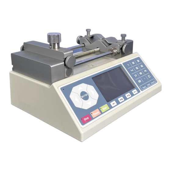
Chemyx Fusion 100 User Manual

Chemyx Fusion 100 User Manual

Fusion series
Hide thumbs Also See for Fusion 100:

Advertisement

ChEmyx
Fusion Series User Manual
Chemyx Inc.
10905 Cash Road
Stafford, TX 77477 USA
www.chemyx.com
Intellectual Property
which is otherwise the property of Chemyx Inc. or its suppliers relating to the Chemyx
syringe pumps, including but not limited to, accessories, parts or software relating thereto
(Chemyx Syringe pumps), are proprietary to federal and state laws, and international treaty
provisions. Intellectual Property includes but is not limited to, inventions (patentable or
unpatentable), patents, trade secrets, copyrights, software, firmware, computer programs,
and related documentation and other works of authorship. Moreover, you agree that you
will not, and will not attempt to, modify, prepare derivative works of, reverse engineer,
disassemble the Chemyx syringe pumps, decompile or otherwise attempt to create source
code from the related software/firmware. No title to or ownership in Intellectual Property is
transferred to you. All applicable rights of the Intellectual Property shall remain with
Chemyx and its suppliers.
All Intellectual Properties, as defined below, owned by or
1

Advertisement

Table of Contents
loading
Need help?

Need help?

Do you have a question about the Fusion 100 and is the answer not in the manual?

Questions and answers

Subscribe to Our Youtube Channel

Summary of Contents for Chemyx Fusion 100

  • Page 1 Intellectual Property All Intellectual Properties, as defined below, owned by or which is otherwise the property of Chemyx Inc. or its suppliers relating to the Chemyx syringe pumps, including but not limited to, accessories, parts or software relating thereto (Chemyx Syringe pumps), are proprietary to federal and state laws, and international treaty provisions.
  • Page 3 Signature on behalf of manufacturer: ________________________ Authority: Jeff Wu, Senior Engineer, Chemyx, Inc. Date: January 1, 2016 Attention! The attention of the specifier, purchaser, installer, or user is drawn to special measures and limitations to use which must be observed when these products are taken into service to maintain compliance with the above directives.
  • Page 4: Table Of Contents

    Operating Instructions Syringe Loading Running the Pump Interface Pump Maintenance Computer Control (RS232 Operation) Cable Requirements RS232 Port Settings RS232 Communication Protocols Testing Communication in HyperTerminal 19 USB to RS232 Dongle Converters TTL, Daisy Chaining, Chemyx Software Appendices Fuse Replacement...
  • Page 5: Manual Description

    Chemyx will issue a Return Authorization (RA) number to you. Repairs Chemyx can repair any syringe pump without major damage. You must contact either by e- mail or phone Chemyx Inc. before returning a product. Chemyx will issue a Return Authorization (RA) number to you.
  • Page 6: Dead Pixel Policy

    Removal of the serial number label voids your warranty. Calibration Chemyx Pumps are pre-calibrated upon arrival to your site. All calibrated parameters are within stated accuracy and precision specifications of the pump. Although the pump might be highly accurate different syringes have much greater error from Glass at 1% to Plastic at...
  • Page 7: Operational Safety

    Please read the following safety precautions to ensure personal safety and operational longevity of the Chemyx syringe pump. Chemyx, Inc. is not responsible for the equipment if used in a manner not specified by the manufacturer; warranty coverage provided by the equipment may be dropped as a result.
  • Page 8: Technical Specifications

    Technical Specifications Note: The step resolution stated is the minimum step resolution achieved by a pump. Fusion 100 Syringe size 0.5 microliter to 60 milliliter Voltage operating range 115V~240V, 0.25 A, 55-60 Hz Drive mechanism Stepper motor Step resolution (advance per microstep) 0.198 microns...
  • Page 9: Principle Of Operation

    Principle of Operation All Chemyx Fusion series syringe pumps are driven via a stepping motor that drives a lead screw and Pusher Block. The resulting action ejects fluid from the barrel of a syringe. When withdrawing the operation is the same with only the motor reversing direction.
  • Page 10: Pump Features

    Pump Features A: Pusher block – locking mechanism varies B: Spring loaded syringe holder C: Withdraw holder (Fusion 200 only) D: Locking nut E: Safety nut F: Numeric keypad G: LCD screen H: Directional keypad I: Start button J: Pause button K: Stop button Note: Fusion 400 systems have 4 channel screw clamp holders.
  • Page 11: Power And Fuse

    Features continued A: Power switch B: Power plug C: 2 Amp fuse D: Voltage Converter E: TTL port USB – B Receptacle F: D9 RS232 serial port...
  • Page 12: Alarms

    Features continued Alarms Audible Alarms will sound in case of a stall and on power on. Stall Detection Stall detection occurs when an optical detector used in verifying expected movement of the motor detects jamming or excessive pressure. In the case of severe stalls from corroded guide rods, the mechanical locking nut will decouple and unlock the pusher block Modes of Operation Infuse:...
  • Page 13: Keypad Interface

    Keypad Interface The green circles represent depressible buttons on the membrane surface. A) Navigation controls The navigation key pad is for tabbing between inputs on the interface. Once you select an input the enter button is used to confirm the input to memory. B) Pump controls The pump controls are used for starting pausing and stopping the pump.
  • Page 14: Operating Instructions

    Operating Instructions Syringe Loading Place the syringe into one of the V shaped slots by lifting the spring clamp (part A). Depress the locking nut (Part C) to release the pusher block (Part B). The pusher block should be pressed firm against the plunger of the syringe before initiating pumping.
  • Page 15 2) After the startup screen a unit selection screen will appear. Ml/Min is the default setting for the Fusion 100 and 200 series. ul/min is the default setting for Fusion 400 series pump. Use the arrow keys to tab your selection up and down and press enter to accept your selection.
  • Page 16: Pump Maintenance

    Pump Maintenance Chemyx pumps require limited maintenance that can be performed with minimal downtime and effort. Proper maintenance of your pump will ensure the system’s operating life to over 5 years. On a routine basis, the following procedures should be...
  • Page 17: Computer Control (Rs232 Operation)

    Computer Control (RS232 Operation) Cable Requirements In order to interface to a PC you need the following hardware cable pictured below: DB9 Serial Cable Male to Female – Straight through configuration. Do not purchase a “Null Modem,” “crossover,” or “crossed over” cables. RS232 Port Settings Before interfacing with a PC, make sure a RS232 port exists on your PC.
  • Page 18: Rs232 Port Settings

    RS232 Port Settings (continued) Baud Rate - 9600, Data Bits - 8, Parity - none, Stop bits - 1, Flow control – none. Most programming packages like LabView, LabWindows and Visual Studio will allow you to program comport settings dynamically in program. RS232 Communication Protocols Protocols: Resulting Action by Pump...
  • Page 19: Rs232 Communication Protocols

    Due to the large numbers of computers made without RS232 ports, USB to RS232 dongles have been popular to “emulate” a RS232 port. Most but not all USB to RS232 dongles work with chemyx pumps due to driver conflict issues.
  • Page 20: Ttl, Daisy Chaining, Chemyx Software

    TTL is a holdover from classical syringe pumps built in the 1970s before RS232 ports existed. However Chemyx does have a TTL port grandfathered in for triggering starts and stops. The TTL port has a USB-B receiver configuration. TTL works with Chemyx’s foot switch, hand switch or parallel switches.
  • Page 21: Appendices

    If the fuse breaks, no power will be supplied to the pump. Chemyx syringe pumps come with a complimentary backup fuse inside the pump. Please follow the instructions below on how to access the fuse holder and replace a broken fuse.
  • Page 22 Step 2: Remove the fuse holder from the power plug. There is a small indentation on the bottom edge of the power plug. A small coin or screwdriver may be needed to remove the fuse holder from the pump. There are 2 fuses in the fuse holder. The exposed fuse in the back is the fuse that is being currently used.
  • Page 23 Step 4: Remove the broken fuse from the active slot in the holder. Most of the time and broken fuse will be visible to the naked eye. Remove the back-up fuse from the plastic casing represented below by the check mark.
  • Page 24 Chemyx www.chemyx.com Inc. Parts List Part Compatible Number Item Description Options Pump systems ▲▲▲ 10010 Fusion 100 ▲▲▲▲▲ 10020 Fusion 200 ▲▲▲ 10040 Fusion 400 ▲ 10050 NanoJet Options and accessories ▲ 10002 10 channel infuse/withdraw holder ▲ 10003 In-pump multi-step automation program ▲...

Table of Contents