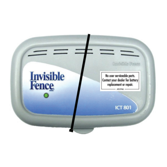
Summary of Contents for INVISIBLE FENCE ICT 801
- Page 1 ICT 801 & ICT 802 Transmitters R21/R22 v4 Computer Collar Units ® Installation Manual ICT 801 www.invisiblefence.com...
- Page 2 14 AWG Jacket PE .045” The ICT 801 and ICT 802 are programmable to transmit a digital signal either at 7KHz or at 10KHz. The ICT 801 and ICT 802 Transmitters are only compatible with the R21/R22 v4 Computer Collar unit.
- Page 3 1. Strip approximately ¼ inch (6.3mm) of insulation from each end of the signal field wires (in-ground containment loop). Using your finger, depress the tab of one red connector (marked LOOP) on the Lightning Protector. Insert one stripped end of the signal field wire into the red connector hole.
- Page 4 ® Ground Fault Circuit Interrupter (GFCI) outlet. In rare cases, lightning strikes or overload fault conditions may cause the GFCI to trip. You must instruct the homeowner to reset the tripped GFCI outlet for the Invisible Fence ® Brand pet containment system to function properly.
- Page 5 User Settings and Functions for ICT 801 Transmitter: Loop 1: Loop 1 is always functioning on the ICT 801. (No indicator light on the circuit board.) L1 Freq.: Select either 7K or 10K signal for Loop 1. The default setting is 7K.
- Page 6 User Settings and Functions for ICT 802 Transmitter: Loop 1: Used to turn Loop 1 LED circuitry ON or OFF. If OFF is selected, all LEDs for Loop 1 will not light. L1 Freq.: Select either 7K or 10K signal for Loop 1. The default setting is 7K.
- Page 7 Typical ICT 801 Installation The following requirement applies to installations within the European community: When using the ICT-801 or the ICT-802 transmitter in the 10KHz transmission mode, the maximum loop area must be no greater than 1,697 square meters. If larger loop size installations are required, the installer is required to use the 7KHz transmission mode in order to comply with the R&TTE regulations.
- Page 8 1. Press and hold the S1 button for approximately 4 seconds until a. For ICT 801: The L1 Freq. LED begins to blink. b. For ICT 802: The Loop 1 LED begins to blink. 2. Release the S1 button.
-
Page 9: Primary Power
ICT 802 Transmitter: AC Adapter Model 04-100-0018-01 (Large transformer) Backup Battery Power The ICT 801 and ICT 802 Transmitters continue to function in the event of a power outage when connected to a fully charged backup battery system. A fully charged 12VDC battery with a 5.0Ah (Amp hours) rating provides enough power to the system for approximately 10 hours with the signal field set to the maximum width. - Page 10 There is one signal field adjustment knob on the ICT 801 transmitter and two signal field adjustment knobs on the ICT 802 transmitter. See page 5 or 6 as appropriate for location of signal field adjustment knobs.
- Page 11 Setting the Break-Alert Detection Level: ® The Break Alert alarm can be set to activate when the signal field width is reduced by 25% or more of the set signal field width. Read the entire procedure before performing. Only the loops turned on will be programmed. Option #1: To set the Break Alert to activate when a 25% reduction in set signal field width occurs: 1.
- Page 12 ® pet’s coat, weight, and age change. The pet’s coat may change from season to season. 5. Allow the pet to become accustomed to its new Invisible Fence Brand Computer Collar unit. ®...
- Page 13 • YELLOW (4.1 & 4.2 only) = The Power Cap unit is low. Replace as soon as possible. ® • RED = The Power Cap unit is dead. Replace immediately. Do not rely on the Invisible Fence Brand ® ®...
- Page 14 ® of times the pet challenges the system boundary, and improper collar fit can all reduce Power Cap ® unit life. Warning: The use of any power source other than an Invisible Fence Brand Power Cap unit will ® ®...
-
Page 15: Important Warnings
Please see page 14 of your manual for instructions on how to remove the battery pack ® for separate disposal. Transmitter: At the end of product life of the Transmitter, please contact your Invisible Fence Brand Dealer ® to receive instructions on proper disposal of the backup battery (if installed). Please do not dispose of the unit in household or municipal waste. - Page 16 Compliance US and Canada FCC ID: KZ3-050261 IC: 2430A-050261 This device complies with Industry Canada rules. This device complies with part 15 of the FCC Rules. Operation is subject to the following two conditions: (1) This device may not cause harmful interference, and (2) this device must accept any interference received, including interference that may cause undesired operation.


Need help?
Do you have a question about the ICT 801 and is the answer not in the manual?
Questions and answers
Beeping sound every 4 minutes
If the INVISIBLE FENCE ICT 801 beeps every 4 minutes, it likely indicates a failure condition such as a loop wire break, AC power failure, or a defective/low backup battery, depending on the status LED color and pattern. Refer to the LED color and alarm pattern for exact diagnosis.
This answer is automatically generated
Red light on when plugged in and beeps constantly
A red light and constant beeping on the INVISIBLE FENCE ICT 801 indicate either a loop wire break or a decrease in the signal field. This issue can be silenced by pressing the S1 or S2 button.
This answer is automatically generated