
Related Manuals for DragonWave Horizon COMPACT


Summary of Contents for DragonWave Horizon COMPACT
- Page 1 Horizon COMPACT Wireless Ethernet Release 1.01.01 Product Manual - Volume 1 Version 1.4...
- Page 3 NOTICE This document contains confidential information, which is proprietary to DragonWave. No part of its contents can be used, copied, disclosed, or conveyed to any party in any manner whatsoever without prior written permission from DragonWave Inc. Copyright © 2001-2008 DragonWave Inc.
-
Page 4: Table Of Contents
IP A ..............23 ECOVERY OF DDRESS AND ERIAL UMBERS ............... 23 HANGING AND DDING AMES AND ASSWORDS 6.5.1 ............23 HANGING THE UPER AME AND ASSWORD Horizon Compact Release 1.01.01 Wireless Ethernet Product User Manual – Volume 1... - Page 5 11.10 (SNTP) ................49 ONFIGURING THE OURCE 11.11 (AAM) ................50 UTOMATIC DAPTIVE ODULATION 11.12 ................. 51 ORIZON OMPACT HROUGHPUT OUBLING 11.13 ....................... 51 ORIZON EDUNDANCY Horizon Compact Release 1.01.01 Wireless Ethernet Product User Manual – Volume 1...
- Page 6 A – L CLI C ..............69 PPENDIX IST OF OMMANDS B – S ............... 71 PPENDIX AFETY NFORMATION C - R ..........75 PPENDIX EGULATORY OMPLIANCE NFORMATION Horizon Compact Release 1.01.01 Wireless Ethernet Product User Manual – Volume 1...
- Page 7 – S – ......55 IGURE EDUNDANCY ONNECTIONS INGLE WIRE OPTION OPTICAL INTERFACE 11-1 W ..................59 IGURE NTER FACE CREEN 11-2 R ......................62 IGURE ADIO OOPBACK Horizon Compact Release 1.01.01 Wireless Ethernet Product User Manual – Volume 1...
- Page 8 NTENNA AINS AND IDTHS ELECTED REQUENCIES 10-1 B (50 M H )..46 ABLE ANDWIDTH PERATING ODE AND ODULATION CHEME HANNEL BANDWIDTH 10-2 T ......................... 50 ABLE OURCES Horizon Compact Release 1.01.01 Wireless Ethernet Product User Manual – Volume 1...
-
Page 9: User Manual Structure
Volume 1 • Volume 3 – contains a complete list of the frequency tables associated with the radio bands supported by the Horizon Compact Horizon Compact Release 1.01.01 Wireless Ethernet Product User Manual – Volume 1... - Page 10 DragonWave Inc. This page left blank intentionally Horizon Compact Release 1.01.01 Wireless Ethernet Product User Manual – Volume 1...
-
Page 11: Introduction To Horizon Compact
High Capacity Native Ethernet Wireless Gigabit Ethernet Designed as an Ethernet platform from the ground up, the DragonWave Horizon Compact meet s the critical needs demanded by carrier class customers delivering a wireless GigE/100bT connection of up to 800 Mbps full duplex over licensed or unlicensed frequency allocations. -
Page 12: Applications
Horizon Compact enables rapid network expansion with remote scalability from 10 Mbps to 800 Mbps. With Horizon Compact the radio and modem are integrated into a single all-outdoor element attached directly to the antenna, allowing simple integration and eliminating any impact on the WiMAX base station footprint. -
Page 13: Technical Specifications
Introduction to Horizon Compact Technical Specifications Frequencies Power 6 GHz FCC/IC/ETSI/ITU/AUS/NZ/ RUS Input -36 VDC to -60 VDC 7 GHz ETSI/ITU/NZ/MEX Optional Adapter 110/240 VAC 8 GHz IC/ETSI/ITU/UK/NZ/RUS 11 GHz FCC/IC/ETSI/ITU Consumption (per link end) 20 Watts (LP) 47 Watts (HP) - Page 14 DragonWave Inc. This page left blank intentionally Horizon Compact Release 1.01.01 Wireless Ethernet Product User Manual – Volume 1...
-
Page 15: Physical Description
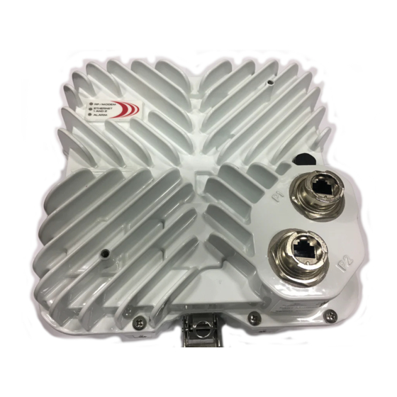
3.0 Physical Description Horizon Compact is an integrated Ethernet modem and microwave radio transceiver, housed in a rugged weatherproof housing. It is provided with two weatherproof connectors, Port 1 and Port 2. Port 1, copper 10/100/1000 Base-t, or optional optical interface, carries data and optional in-band management traffic. -
Page 16: Cabling
One connector (GigE – Port 1) is for data traffic and optional in- band management. Power (-36 to -60 V DC) is provided by an optional mains power adaptor and supplied to the Horizon Compact using Power on Ethernet ( PonE) techniques, which incorporates both power and network transient suppression (See Section 8.1). -
Page 17: Lightning Protection
The DPRM system allows two Horizon Compact units to be assembled to a single antenna. The antenna used is no different to that used for a single unit. One Horizon Compact unit is mounted for horizontal polarity and the other for vertical polarity. Both units can transmit and receive simultaneously. This allows a link to carry up to 800 Mbps of Ethernet traffic. -
Page 18: Power Switch Radio Mount (Psrm)
Disadvantages include a 4 dB loss in signal when operating on the primary systems at each end of the link and an 8.5 dB loss in signal when a secondary radio is activated (one end running on Primary and other end operating on secondary). Horizon Compact Release 1.01.01 Wireless Ethernet Product User Manual – Volume 1... -
Page 19: Installation Requirements
A -INK-HCC-AC-NA -R1 Horizon Compact, Copper Connectors AC Install Kit , 4 Glands and 8 Connectors A -INK-HCC-AD-NA -R1 Horizon Compact, Copper Connectors Half AC, Half DC Install Kit , 4 Glands and 8 Connectors A -INK-HCI-AC-NA -R1 Horizon Compact, Inband MGMT Copper Connectors AC Install Kit , 2 Glands and 4... -
Page 20: Hoisting Lug
Hoisting Lug A hoisting lug is shipped with each Horizon Compact (two per link). Th i s can be bolted onto the horizon with the supplied bolt, using any of the available threaded holes, and used for attaching a line for hoisting or carrying the unit into position on a tower or pole. -
Page 21: Ethernet Cabling From Horizon To Ethernet Switch
Note: Straight through Ethernet cables must be used between the PonE adapter and the Horizon. The use of a cross-over type will result in damage to the Horizon Compact unit. The PonE unit contains surge arrestors and must be grounded according to local or regional Electrical Codes. -
Page 22: Assembling The Rj-45 Connector
Weatherproof RJ-45 connector shells are used for connecting the CAT5E cable, leading from the power- on- Ethernet power supply and network connections, to the Horizon Compact. Cables and connectors may be purchased from DragonWave or may be constructed or supplied by the customer. -
Page 23: Push Fit" Style
Horizon connector to the Horizon Compact. Only use straight Compact BEFORE through cable connections. applying power to the system at the PonE/surge unit. See 8.1 for more details. Horizon Compact Release 1.01.01 Wireless Ethernet Product User Manual – Volume 1... - Page 24 DragonWave Inc. This page left blank intentionally Horizon Compact Release 1.01.01 Wireless Ethernet Product User Manual – Volume 1...
-
Page 25: Powering The Horizon Compact
CAUTION Connect the Horizon Compact unit to the PonE adapter correctly BEFORE turning on power. Connect Port 1 of the Horizon Compact to the correct socket on the PonE adapter using a straight through Ethernet cable (see caution above). Connect the Ethernet port on the PC to the network input socket on the PonE/surge unit, using a straight through Ethernet cable. -
Page 26: Optical Interface
CAT5) at the Transtector end is terminated as shown in Figure 5- 3. The same Transtector type used in an AirPair ODU installation may also be used. Figure 5-2 Connecting Power to the Horizon Compact – optical interface Horizon Compact Release 1.01.01... - Page 27 Pin Signal Color TP0+ White/Green TP0- Green TP1 + White/Orange TP2+ Blue TP2- White/ Blue TP1- Orange TP3+ White/Brown TP3- Brown Figure 5-3 RJ-45 connector pinout – Port 2 management Horizon Compact Release 1.01.01 Wireless Ethernet Product User Manual – Volume 1...
- Page 28 DragonWave Inc. This page left blank intentionally Horizon Compact Release 1.01.01 Wireless Ethernet Product User Manual – Volume 1...
-
Page 29: Initial Configuration
Note: If the management interface type happens to be set to “out-of -band”, management through Port 1 (GigE port) will not be possible. In this case connect your laptop or PC to the Horizon Compact via Port 2. In both copper and optical Horizon variants , Port 2 has a copper interface. -
Page 30: Using The Web Interface
Configuring Radio Band and Frequency Channels Both Horizon Compact units in a system (near and far end) have to be configured with the same radio band. Volume 3 of this manual lists all the radio bands supported by the Horizon Compact system. The radio band selected must match that for which the Horizon Compact units have been manufactured. - Page 31 Note 2: You will also need to click on the “Reset system” button to make these entries effective. Optionally, this can be left until all the initial configuration parameters have been entered before issuing the command (See 6.3.2 step 5). Horizon Compact Release 1.01.01 Wireless Ethernet Product User Manual – Volume 1...
-
Page 32: Using Telnet
(192.168.10.100) and subnet mask (255.255.0.0). The default address is used to communicate with the Horizon Compact for initial configuration purposes, such as entering the IP address that the unit will have in the network to which it is to be connected. IP address information is entered in the following manner: 6.3.1... -
Page 33: Recovery Of Ip Address And Serial Numbers
Horizon Compact system but have some restrictions for changes to configuration No default noc or admin user accounts are configured when the Horizon Compact leaves the factory. Account names and passwords are case sensitive. There can be no duplication of names or passwords across all user levels. -
Page 34: Adding Or Changing Noc
The system responds: Index: Enter the <index #> where <index #> is from 1 to 5 and represents one of the 5 available accounts. The system responds: UserName: Horizon Compact Release 1.01.01 Wireless Ethernet Product User Manual – Volume 1... - Page 35 Note: the new account settings must be saved, otherwise they will be lost after the next system reset. The user must perform the save mib command in order to save the changes. Horizon Compact Release 1.01.01 Wireless Ethernet Product User Manual – Volume 1...
-
Page 36: Adding Or Changinga
Enter the <index #> where <index #> is from 1 to 50 and represents one of the 50 available accounts. The system responds: UserName: Enter the desired username for this account. The system responds: Verify UserName: Horizon Compact Release 1.01.01 Wireless Ethernet Product User Manual – Volume 1... -
Page 37: Logging Out
When accessing using the Web browser, closing the browser will log you out of the system. 6.6.1 Session Time Out After 10 minutes of inactivity, Horizon Compact units will automatically terminate the login session. Horizon Compact Release 1.01.01 Wireless Ethernet Product User Manual – Volume 1... - Page 38 DragonWave Inc. This page left blank intentionally Horizon Compact Release 1.01.01 Wireless Ethernet Product User Manual – Volume 1...
-
Page 39: Antenna Mounting And 7.1 Polarity
7.0 Antenna Mounting and Tower Specifications The Horizon Compact unit clip mounts onto a range of antennas, providing a variety of gain and range options. The same mounting system is used for all sizes of antenna. The Horizon Compact has four, integral, spring loaded, mounting clips. The antennas are provided with four mounting lugs, onto which the mounting clips attach. -
Page 40: Unlicensed Radio Bands
The radio frequency polarity is indicated by an arrow molded into the Horizon Compact housing. Attach the Horizon Compact to the antenna so that the arrow points either vertically or horizontally, as required, when the assembly is attached to the mounting post or tower. With the arrow horizontal (pointing to the left) –... -
Page 41: Antenna Location
Volume 2 of this manual. >45° 2.5 m 30 cm up to and greater than >30 cm 12.5 m Roof Roof Roof Line Line Line Figure 7-3 Recommended Antenna Placement Horizon Compact Release 1.01.01 Wireless Ethernet Product User Manual – Volume 1... -
Page 42: Pole And Tower Specifications
Pole and Tower Specifications It is important that mounting posts or towers used meet the DragonWave specifications for rigidity to minimize the effects of t w ist and sway on the alignment of the link. Note that the maximum twist and sway angle allowable is equal to half of the antenna beam width. - Page 43 Installation Requirements Horizon Compact Release 1.01.01 Wireless Ethernet Product User Manual – Volume 1...
-
Page 44: Grounding , Power And 8.1 Power On Ethernet (Pon E)
Use 6 AWG or larger copper wire to connect from Horizon case grounding point to ground. There are two grounding points on each of the four sides of the Horizon case. Figure 8-1 Horizon Compact case grounding point Horizon Compact Release 1.01.01... - Page 45 Horizon consumes a nominal 20 Watts (standard power), or 40 Watts (high power variant) from the -48 VDC supply. All eight of the wires in the Ethernet cable are used to carry power to the Horizon Compact unit. The Power on Ethernet surge arrestor unit is rated at 2 amps.
- Page 46 Additional cable security can be added by applying cable clips to the cables, as close to the clamp bar as possible, as shown in Figure 8-3. Cable clip Figure 8-3 Ethernet cable clip Horizon Compact Release 1.01.01 Wireless Ethernet Product User Manual – Volume 1...
- Page 47 Grounding, Power and Surge Arrestors This page left blank intentionally Horizon Compact Release 1.01.01 Wireless Ethernet Product User Manual – Volume 1...
-
Page 48: Preparing For Alignment
9.0 Preparing for Alignment The Horizon Compact and antenna assembly is attached to the mounting post, or tower, with a specialized mounting bracket that allows fine orientation adjustment of the Horizon/antenna assembly. The same mounting bracket is used for all antenna sizes. -
Page 49: Received Signal Level (Rsl) M
Preparing for Alignment Received Signal Level (RSL) Measurements To accurately align the Horizon Compact to its far end peer, you need to monitor the received signal level (RSL). There are two recommended methods for monitoring RSL. These are: Use the CLI command set alignment on to activate the alignment feature at the BNC connector located on the side of the unit. -
Page 50: Three Important Factors
Clear Line of Sight (LoS) The DragonWave Horizon Compact requires a clear LoS between the units at each end of the link. You must be able to see an unobstructed view of the antennas from each end. Avoid obstacles that are close to the LoS mid-way between antennas, but not blocking it, as this can have a negative impact on signal quality (Fresnel zone clearance). -
Page 51: Lignment
Preparing for Alignment This page left blank intentionally Horizon Compact Release 1.01.01 Wireless Ethernet Product User Manual – Volume 1... -
Page 52: Aligning The Antennas
– one end horizontal and the other vertical • path issues - obstructions such as trees, hills, or buildings within the beamwidth • path clearance issues such as diffraction, partial obstruction, Fresnel zone issues Horizon Compact Release 1.01.01 Wireless Ethernet Product User Manual – Volume 1... -
Page 53: Signs Of A Healthy Link
Unchanneli z ed power reading should be within 6 dB of the RSL reading. If the Unchannelized power drops below -75 dB, then it is likely that there is no signal being presented at the radio portion of Horizon Compact. Check alarms. •... -
Page 54: Advanced Configuration
Horizon Compact memory, so once a user is verif ied by the RADIUS server the access level is assigned by the Horizon Compact (provided that that user is a valid user on that unit). Any user that is validated by the RADIUS server, but is not found in the Horizon Compact user authentication list, can gain access to the unit but only at an admin user level. -
Page 55: 802.1P Priority Queuing
Horizon Compact supports the eight Classes of Service (CoS ) levels (0-7) defined within 802.1P. There are four CoS Queues within Horizon Compact, numbered 1 to 4. Any of the eight CoS levels can be assigned to any of the four Horizon Compact CoS Queues. Horizon can also be configured to use the priority bits found in the DSCP field of IP headers. - Page 56 Queue 1. Horizon Compact is also able to manage Q- in-Q or Super VLAN traffic. The system can be configured to use either an encapsulated frame’s priority tag or the encapsulating frame’s priority tag, in determining priority handling.
- Page 57 11.5 Horizon Compact Throughput Speed When you purchase a Horizon Compact system you receive a unit capable of giving a throughput speed of up to 400 Mbps. However, the actual throughput speed achievable for any given system depends on the specific throughput speed key that you purchased with the system You can upgrade your system to a higher licensed throughput speed (up to 400 Mbps) by purchasing an upgrade key and reprogramming your system.
- Page 58 -50 dB during fade conditions. RSL threshold levels that trigger power changes, the maximum power change allowed, and a hysteresis factor are preset at values which optimize the operation of the Horizon Compact system. A fade factor of 5dB/second can be handled.
-
Page 59: Lignment
11.7 Horizon Compact Authentication This feature is only necessary if you wish to restrict communication from a Horizon Compact unit to a specific peer or to a group of Horizon Compact units. Authenticat ion is generally used as a security measure. - Page 60 Date and time information can be entered into the system using CLI command set date time [dd/dd/yyyy hh:mm:ss:ms] press Enter. The date and time settings in Horizon Compact are not maintained if a power outage is experienced. To ensure that set system date and time are always accurate, the system can poll known time sources and update time information on an ongoing basis.
- Page 61 (a number of system modes, which includes the modulation scheme, are available for any given radio band, see Section 6.2), if the Horizon Compact units detect errored, but corrected, frames (caused by reduced RSL levels) . The original modulation scheme will be restored once preset parameters indicate that conditions are suitable for returning to the original modulation scheme (and return to the original bandwidth).
-
Page 62: Bnc Connector
11.13.1 BNC Connector The BNC connector on the side of the Horizon Compact serves a dual purpose. It can be configured as a source for field strength measurements during antenna alignment, or configured to provide a redundancy switch signal to a second Horizon Compact sy stem mounted close by. For redundancy, t h e BNC connectors on both units are interconnected with a coaxial cable. -
Page 63: Two Wire Option
NOTE: For clarity, the PonE power adapter and surge arrestor have been omitted from the diagram. Both the Port 1 and Port 2 Ethernet connections and the power feed via Port 1 must be protected from transients. Horizon Compact Release 1.01.01 Wireless Ethernet Product User Manual – Volume 1... - Page 64 NOTE: For clarity, the Transtector surge arrestor has been omitted from the diagram. Both the Ethernet management feed to Port 2 and the power feed, via Port 2, must be protected from transients. Horizon Compact Release 1.01.01 Wireless Ethernet Product User Manual – Volume 1...
-
Page 65: Single Wire Option With The Psrm
NOTE: For clarity, the PonE power adapter and surge arrestor have been omitted from the diagrams. Both Port 1 Ethernet connections and the power feed via Port 1 must be protected from transients. Horizon Compact Release 1.01.01 Wireless Ethernet Product User Manual – Volume 1... - Page 66 Figure 11-5 Redundancy Connections – Single wire option – optical interface NOTE: For clarity, the Transtector surge arrestor has been omitted from the diagram. The power feed must be protected from transients. Horizon Compact Release 1.01.01 Wireless Ethernet Product User Manual – Volume 1...
- Page 67 Advanced Configuration Features This page left blank intentionally Horizon Compact Release 1.01.01 Wireless Ethernet Product User Manual – Volume 1...
-
Page 68: Horizon Management
When the network management interface is set to "port1" all management traffic must arrive on Port 1, or it will be ignored by the syste m. Configuration and management of the Horizon Compact system can be accomplished through a Telnet, or SSH, session, and although the Telnet session is intermixed with user traffic, the Telnet session occupies very little bandwidth (in the order of kbps) and therefore has almost no effect on user traffic throughput. -
Page 69: Management Through Port 2 (Out-Of-Band)
Telnet session. A secure shell (SSH) protocol can be enabled in the Horizon Compact system to ensure that access to the units is restricted to authorized clients. Horizon Compact uses the Secure Shell SSH2 server programme to create the secure environment for Telnet ses sions. -
Page 70: Web Interface
Formatted: Font: 8 pt, Bold Formatted: Font: 8 pt, Bold 12.5 Web Interface Formatted: Font: 8 pt, Bold The Horizon Compact Web interface runs in a standard browser. To log on see Section 6.1.3. Formatted: Font: 8 pt, Bold Deleted: ¶ 12.5.1 Home Screen ¶... -
Page 71: Performance Screen
Ethernet Quality of Service SNMP Traps Configuration 12.5.4 Diagnostics Screen The diagnostics screen has a link that directs you to the DragonWave support Web page, where you can download diagnostics programmes. Horizon Compact Release 1.01.01 Wireless Ethernet Product User Manual – Volume 1... -
Page 72: Alarms Screen
In order to be able to generate an SSL link, a Web server requires an SSL Certificate. In order to invoke SSL on the Horizon Compact W eb server, an SSL certificate must be generated on the Horizon Compact. -
Page 73: Event And Performance Logs
12.7 Event and Performance Logs The Horizon Compact system supports two logs, the Events Log and the Performance Log. Each can be used to trace the behaviour of the system over time. The Events Log is invoked or disabled by issuing the CLI command set logging [on/off] . This log records alarm and reset events. -
Page 74: Alarms List
• Modem equalizer stress above threshold Frequency File invalid • • Radio RSL Below Threshold AAM running on QPSK modula tion • • SNTP Servers Unreachable Synthesizer Unlock Horizon Compact Release 1.01.01 Wireless Ethernet Product User Manual – Volume 1... - Page 75 Horizon Management This page left blank intentionally Horizon Compact Release 1.01.01 Wireless Ethernet Product User Manual – Volume 1...
-
Page 76: Configuration Backup And Restore
Use the CLI command: copy ftp: <filename> press Enter where <filename> is the name of the file to restore to the Horizon Compact . Follow the prompts. Note that the above command will retrieve the file from the root directory of the ftp server. Adding the path information to the file name will allow you to retrieve it from a specific directory on the ftp server. - Page 77 Horizon Management This page left blank intentionally Horizon Compact Release 1.01.01 Wireless Ethernet Product User Manual – Volume 1...
-
Page 78: Software Upgrades
Horizon Compact system, or use DragonWave’s FTP server site available through the Internet. The Horizon Compact can interact with the most popular FTP servers on a variety of operating systems. Anonymous FTP, as well as a user–supplied username and password are supported. - Page 79 Horizon Management This page left blank intentionally Horizon Compact Release 1.01.01 Wireless Ethernet Product User Manual – Volume 1...
-
Page 80: Appendixa - List Of Cli Commands
Horizon Compact Release 1.01.01 Wireless Ethernet Product User Manual – Volume 1... -
Page 81: Wireless Ethernet Product User Manual – Volume
[on|off] set pause state [on|off] upgrade system licensed speed [speed] [key] set performance logging [on|off] set performance log interval [hr:min:sec] set programmed frequency [index] set qos [on|off] Horizon Compact Release 1.01.01 Wireless Ethernet Product User Manual – Volume 1... -
Page 82: Appendixb - Safety Information
ANSI C95.1, 1991. Proper operation of this radio according to the instructions found in this manual or any other product manuals or user guides for the DragonWave family of products or equipment will result in user exposure that is substantially below the FCC recommended limits. - Page 83 Article 810 of the United States National Electrical Code. Installations Professionel Les appareils Horizon Compact de DragonWave doivent être installés par un personnel professionnel. Le personnel responsable doit s’assurer que l’installation est bien achevée, et qu’elle répond aux exigences de tous les codes de sécurité.
- Page 84 Risque d’électrocution Cet appareil est raccordée à une source de tension de –36 a -60V CD (adapteur fourni par DragonWave), qui doit être isolée de toute autre source de tension et raccordée à une mise à terre isolée. Les produits de DragonWave ne doivent pas être installés près de ligne à...
- Page 85 Appendix C This page left blank intentionally Horizon Compact Release 1.01.01 Wireless Ethernet Product User Manual – Volume 1...
-
Page 86: Appendixc - Regulatory Compliance Information
The Part 15 radio device operates on a non-interference basis with the other devices operating at this frequency. Any changes or modification to said product not expressly approved by DragonWave Inc. could void the user’s authority to operate this device. Horizon Compact Release 1.01.01... - Page 87 If the equipment is not installed and used in accordance with the instruction manual, it can cause harmful interference to radio communications. Horizon Compact Release 1.01.01 Wireless Ethernet Product User Manual – Volume 1...
- Page 88 DragonWave Inc. This page left blank inte ntionally Horizon Compact Release 1.01.01 Wireless Ethernet Product User Manual – Volume 1...
- Page 89 Appendix D Copyright © 2000-2007 DragonWave Inc. Printed in Canada. All rights reserved. Horizon Compact™ Product Manual, 83- 000027-01-01-0 4 Visit us on the Internet at: http://www.dragonwaveinc.com/ Horizon Compact Release 1.01.01 Wireless Ethernet Product User Manual – Volume 1...
Need help?
Do you have a question about the Horizon COMPACT and is the answer not in the manual?
Questions and answers