Table of Contents
Advertisement
Quick Links
Download this manual
See also:
Product Manual
Advertisement
Table of Contents

Related Manuals for DragonWave Horizon COMPACT


Summary of Contents for DragonWave Horizon COMPACT
- Page 1 Horizon COMPACT Wireless Ethernet Release 1.04.07 Product Manual - Volume 1 Version 1.13...
- Page 3 NOTICE This document contains confidential information, which is proprietary to DragonWave. No part of its contents can be used, copied, disclosed, or conveyed to any party in any manner whatsoever without prior written permission from DragonWave Inc. Copyright © 2000 - 2012 DragonWave Inc.
-
Page 4: Table Of Contents
NDOOR IGHTNING RRESTOR ............... 31 OWERING THE ORIZON OMPACT ....................... 31 ROUNDED OWER EEDS – O 1 ....................... 32 OPPER NTERFACE PTION 5.2.1 .................... 32 SING THE UTDOOR Horizon Compact Release 1.04.07 Wireless Ethernet Product User Manual – Volume 1... - Page 5 ....................60 OLE AND OWER PECIFICATIONS ............... 61 OCATING ORIZON OMPACT YSTEMS ........................61 IELD FFECTS S) ......................63 LEAR INE OF IGHT ................. 65 REPARING FOR LIGNMENT Horizon Compact Release 1.04.07 Wireless Ethernet Product User Manual – Volume 1...
- Page 6 ........................86 ULTIPLE YSTEMS A – CLI C ................... 87 PPENDIX OMMAND B – S ................93 PPENDIX AFETY NFORMATION C - R ........... 97 PPENDIX EGULATORY OMPLIANCE NFORMATION Horizon Compact Release 1.04.07 Wireless Ethernet Product User Manual – Volume 1...
- Page 7 OWER PTICAL NTERFACE NDOOR IGHTNING RRESTOR 5-9 O ....... 38 IGURE PTIONAL XTERNAL OWER UTDOOR IGHTNING RRESTOR 7-1 H ..............55 IGURE ORIZON OMPACT SHOWING CLIP MOUNT FEATURES Horizon Compact Release 1.04.07 Wireless Ethernet Product User Manual – Volume 1...
- Page 8 AIN LOBE AND SIDE LOBES DISTANCE OF APPROXIMATELY 10-1 A ................. 74 IGURE LIGNING YSTEMS SING OCAL ANDMARKS 10-2 U ............74 IGURE SING OMPASS EARINGS TO LIGN YSTEMS Horizon Compact Release 1.04.07 Wireless Ethernet Product User Manual – Volume 1...
- Page 9 PPROXIMATE SIZE OF BEAM AT DESTINATION 9-4 D ................72 ABLE EGREES PER EVOLUTION OF DJUSTMENT 10-1 T ................... 73 ABLE ORQUE PECIFICATIONS FOR NTENNAS 14-1 S ....................... 85 ABLE OFTWARE PGRADE Horizon Compact Release 1.04.07 Wireless Ethernet Product User Manual – Volume 1...
-
Page 11: User Manuals
Volume 1 • Volume 3 – contains a complete list of the frequency tables associated with the radio bands supported, and soon to be supported, by the Horizon Compact • This user manual is divided into three volumes:... - Page 12 DragonWave Inc. This page left blank intentionally Horizon Compact Release 1.04.07 Wireless Ethernet Product User Manual – Volume 1...
-
Page 13: Introduction Toh
Dual Polarization Radio Mount (DPRM) to provide up to 800 Mbps of capacity in a single link. Zero-Footprint Option The Horizon Compact is a single, outdoor, compact, weatherproof unit requiring no indoor space and is available with optical and electrical GigE interface options. Enhanced Network Management Horizon Compact fully supports remote management via in-band or out-of-band management, using SNMP (v3, V2c or V1), CLI and Web GUI. -
Page 14: Applications
Horizon Compact enables rapid network expansion with remote scalability from 10 Mbps to 800 Mbps. With Horizon Compact the radio and modem are integrated into a single all-outdoor element attached directly to the antenna, allowing simple integration and eliminating any impact on the WiMAX base station footprint. -
Page 15: Technical Specifications
256 QAM 9.5/19.5 9.5/19.5 9.5/19.5 SP/HP shown for Tx Power Not all modes may be available in all channel sizes. Subject to Throughput based on random frame size change Horizon Compact Release 1.04.07 Wireless Ethernet Product User Manual – Volume 1... - Page 16 DragonWave Inc. This page left blank intentionally Horizon Compact Release 1.04.07 Wireless Ethernet Product User Manual – Volume 1...
-
Page 17: Physical Description
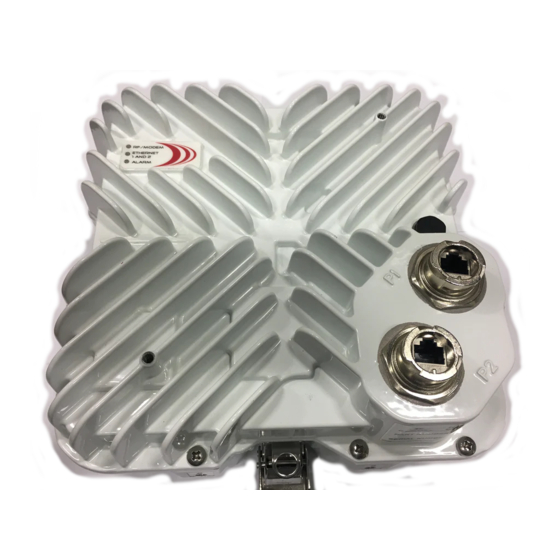
3.0 Physical Description Horizon Compact is an integrated Ethernet modem and microwave radio transceiver, housed in a rugged weatherproof housing. It is provided with two weatherproof connectors, Port 1 and Port 2. Port 1, copper 10/100/1000 Base-t, or optional optical interface, carries data and optional in-band management traffic. -
Page 18: Hoisting Lug
RF/Modem LED = OFF Hoisting Lug A hoisting lug is shipped with each Horizon Compact (two per link). This can be bolted onto the horizon with the supplied bolt, using any of the threaded grounding points, and used for attaching a line for hoisting or carrying the unit into position on a tower or pole. -
Page 19: Ethernet And Power
One connector (GigE – Port 1) is for data traffic and optional in-band management. Power (-36 to -60 V DC) is provided by an optional isolated mains power adaptor and supplied to the Horizon Compact using Power on Ethernet (PonE) techniques via a PonE Power Adapter, which incorporates both power and network Lightning Arrestor. -
Page 20: Lightning Protection
Arrestor Arrestor For the Horizon Compact, optical interface variant, or where PonE is not used to power the Horizon, protection of the power feed and the Ethernet connections is provided by a Lightning Arrestor unit of similar physical design to those described above. For correct installation procedures see Section 4.0. -
Page 21: Adio Mount (Dprm)
The DPRM system allows two Horizon Compact units to be assembled to a single antenna. The antenna used is no different to that used for a single unit. One Horizon Compact unit is mounted for horizontal polarization and the other for vertical polarization. Both units can transmit and receive simultaneously. - Page 22 DragonWave Inc. This page left blank intentionally Horizon Compact Release 1.04.07 Wireless Ethernet Product User Manual – Volume 1...
-
Page 23: Equirements
Horizon Compact, Copper Connectors AC Install Kit (Europe ) - Includes 4 Glands and 8 A-INK-HCC-AC-EU-R1 Connectors Horizon Compact, Copper Connectors Half AC, Half DC Install Kit (N. America) - Includes 4 Glands A-INK-HCC-AD-NA-R1 and 8 Connectors Horizon Compact, Copper Connectors Half AC, Half DC Install Kit (Europe ) - Includes 4 Glands... - Page 24 Horizon Compact, Inband MGMT Copper Connectors AC Install Kit (Europe )- Includes 2 Glands A-INK-HCI-AC-EU-R1 and 4 Connectors Horizon Compact, Inband MGMT Copper Connectors Half AC, Half DC Install Kit (N. America) - A-INK-HCI-AD-NA-R1 Includes 2 Glands and 4 Connectors...
-
Page 25: Installation R 4.1 System Grounding
Before Ethernet cables enter buildings, voltages shall be clamped down to SELV by approved type primary protectors. For the copper interface option, proper use of the DragonWave Horizon PonE unit provides lightning and surge protection for the connected network. The PonE unit shall be installed according to local Electrical Safety Codes. -
Page 26: Outdoor Equipment
This section outlines the indoor and outdoor grounding scheme recommended in the installation of the complete Horizon Compact IDU/ODU system. The primary aim of the grounding scheme considered is electrical safety from lightning strikes, induced current surges and ground-potential differences, as well as safety of the ac primary supply at the customer interface. -
Page 27: Figure 4-2 Grounding Of Non
Weatherproof all connections using a potting compound or other gas-tight material, to prevent corrosion. Ground radio to post To Modem Figure 4-2 Grounding of Non-Penetrating Roof Mount Horizon Compact Release 1.04.07 Wireless Ethernet Product User Manual – Volume 1... -
Page 28: Figure 4-3 Grounding Ofe
DragonWave Inc. Figure 4-3 Grounding of Equipment in Cabinet Figure 4-4 Grounding of Tower Mount – Horizon Compact System Horizon Compact Release 1.04.07 Wireless Ethernet Product User Manual – Volume 1... -
Page 29: On E)
Horizon consumes a nominal 20 Watts (standard power), or 40 Watts (high power variant) from the -48 VDC supply. All eight of the wires in the Ethernet cable are used to carry power to the Horizon Compact unit. The Power on Ethernet Lightning Arrestor unit is rated at 2 amps. -
Page 30: Figure 4-5 Outdoor Lightning
Section 4.4.2). Cables with sheath diameters of between 0.35” and 0.62” can be accommodated when the special grommet is removed. Figure 4-6 Indoor Lightning Arrestor and Power injector Horizon Compact Release 1.04.07 Wireless Ethernet Product User Manual – Volume 1... -
Page 31: Nits
The importance of protecting network and power systems from damaging voltage transients, induced by lightning and other sources, cannot be over emphasized. DragonWave supplies four types of Lightning Arrestor Units. • Outdoor rated Lightning Arrestor with integrated power on Ethernet (PonE) •... -
Page 32: Figure 4-9 Two Indoor Units In
(screw slots will accommodate 6mm (1/4”) diameter screws on 7.2” centres, horizontally). Figure 4-9 Two Indoor Units in Rack Mount Adapter Wall mounting brackets are removable Figure 4-10 Indoor Unit with Wall Mount Brackets Horizon Compact Release 1.04.07 Wireless Ethernet Product User Manual – Volume 1... -
Page 33: Figure 4-11 Horizon Compact
Installation Requirements BEP- connect tower ground to shack ground Power feed to shack Figure 4-11 Horizon Compact Installation Horizon Compact Release 1.04.07 Wireless Ethernet Product User Manual – Volume 1... -
Page 34: Figure 4-12 Outdoor Unit Pon
Horizon. The use of a cross-over type, or incorrectly wired CAT5E cables, will cause the PonE power injector to go into an alarm condition and not power up the Horizon Compact. A Status LED indicates the status of the PonE power injector (see Section 5.2.4) The PonE unit contains Lightning Arrestors and must be grounded according to local or regional Electrical Codes. -
Page 35: Seals
PonE unit housing Figure 4-13 Weatherproof Grommet Seals 4.4.3 Using Indoor PonE Unit Figure 4-14 Indoor Unit PonE and RJ45 Connections for Horizon Horizon Compact Release 1.04.07 Wireless Ethernet Product User Manual – Volume 1... -
Page 36: Rj45 Connector
The connector shell must be assembled in a specific manner for it to correctly connect to the Horizon Compact unit. The CAT5E cable is terminated as a straight through connection with a shielded RJ45 connector. This RJ45 connector has to be assembled into the weatherproof connector shell oriented as shown in Figure 4-15. -
Page 37: E Unit
Ensure that shield foil and drain wire of CAT5E outdoor cables are positively connected to the metal head shells of the RJ45 connectors at BOTH ends of the cable! Horizon Compact Release 1.04.07 Wireless Ethernet Product User Manual – Volume 1... -
Page 38: Opper Interface - Option 2
The composite cable provided with this option has an overall shielding and contains two shielded CAT5E cables, a power feed cable and a drain wire/shield connection. All are terminated at the Horizon Compact end in a single MIL specification, multi-pin, connector. This is connected to Port 1, with the vacant Port 2 location fitted with a weatherproof blanking plate. -
Page 39: Ightning Arrestor Unit
Installation Requirements 4.5.2 Using Indoor Lightning Arrestor Unit Figure 4-18 Indoor Lightning Arrestor Unit Ethernet Cabling – Option 2 Figure 4-19 RJ45 connector pinout – Port 2 management. Horizon Compact Release 1.04.07 Wireless Ethernet Product User Manual – Volume 1... - Page 40 DragonWave Inc. This page is left blank intentionally Horizon Compact Release 1.04.07 Wireless Ethernet Product User Manual – Volume 1...
-
Page 41: Orizon Compact
5.0 Powering the Horizon Compact Before an active management session can be started on the Horizon Compact, power needs to be provided to the unit. Read this section completely before applying power to the Horizon Compact. Caution Ensure correct voltage polarity before connecting external DC supply to Horizon Compact Unit. -
Page 42: Ption 1
DragonWave Power on Ethernet (PonE) power injector/Lightning Arrestor. There are two versions of this unit – an outdoor rated unit and an indoor rated unit. Both DragonWave PonE units also include transient and surge suppression components to protect the power supply and network from lightning induced surges and transients. -
Page 43: Figure 5-4 Connecting Power
5.2.3 Steps to Connecting Power 1. Connect Port 1 of the Horizon Compact to the correct socket on the PonE/lightning arrestor using a straight through, shielded, Ethernet cable (see caution above). 2. Connect the Ethernet port on the PC to the network input socket on the PonE/lightning arrestor, using a straight through Ethernet cable, with an unshielded RJ45 connector. -
Page 44: Figure 5-5 Pone Status Led
If any such condition exists, then the PonE adapter will not apply power to the Horizon Compact. The status LED signals the condition of the PonE system if this should occur (see Table 5-1). If the fault condition clears, the system will then attempt to provide power to the Horizon Compact unit, but the LED will continue to indicate that a current/voltage problem had occurred (Alarm history). -
Page 45: Figure 5-6 Outdoor Suppression
A shielded composite cable is available, comprising two CAT5E cables and two twisted pairs power feed cables in a single sheath, terminated at the Horizon Compact connection end in a single MIL specification, multi-pin, connector. The MIL style connector plugs into Port 1 on the Horizon Compact. For network Ethernet connections see Section 4.5. -
Page 46: Using The Indoor
5.3.2 Using the Indoor Lightning Arrestor Unit The power feeds for the Horizon Compact Copper Interface - Option 2, using the indoor Lightning Arrestor unit, are shown in Figure 5-7 Figure 5-7 Indoor Suppression Unit - Power Feed Copper Interface Option 2 Horizon Compact Release 1.04.07... -
Page 47: Optical Interface
CAT5E cable (blue) does not need to be terminated. Note that the Ethernet connection (where used) and power feed to Port 2 must be fed via a DragonWave Lightning Arrestor Unit to protect the network and power systems from transients. Either the Indoor or Outdoor Lightning Arrestor unit may be used depending on the installation. -
Page 48: Alternate Power
The gland fitting on the DragonWave Lightning Arrestor unit accepts and seals a round cable with a jacket diameter between 0.35 and 0.62 inches. The power terminal block will accept up to a maximum of 14 AWG wires. -
Page 49: Initial Configuration
Note: If the management interface type happens to be set to “out-of-band”, management through Port 1 (GigE port) will not be possible. In this case connect your laptop or PC to the Horizon Compact via Port 2. In both copper and optical Horizon variants, Port 2 has a copper interface. -
Page 50: Enhanced Security
With the Enhanced Security option, an initial Super User name and password are provided by DragonWave to the customer. This can be changed by the customer (Super User), once logged on. DragonWave proprietary access is also disabled, meaning that DragonWave personnel will not be able to gain access to the system using the DragonWave proprietary access code, unless the Super User specifically allows it (set dw access on/off). -
Page 51: Logging On
Configuring Radio Band and Frequency Channels Both Horizon Compact units in a system (near and far end) have to be configured with the same radio band. Volume 3 of this manual lists all the radio bands supported by the Horizon Compact system. The radio band selected must match that for which the Horizon Compact units have been manufactured. -
Page 52: Using Telnet
Note that when using 2 Horizon Compacts on the same data path, non-overlapping channels are required when operating above 16QAM. If, however, you must use co-channel operation, then consult DragonWave for installation guidance and installation mount enhancements that are required. -
Page 53: Eb Interface
Note 1: For unlicensed systems, you cannot configure antenna diameter using the Web interface. Note 2: You will also need to check the “Reset” box to make these entries effective. Horizon Compact Release 1.04.07 Wireless Ethernet Product User Manual – Volume 1... -
Page 54: Using Telnet
(192.168.10.100) and subnet mask (255.255.0.0). The default address is used to communicate with the Horizon Compact for initial configuration purposes, such as entering the IP address that the unit will have in the network to which it is to be connected. IP address information is entered in the following manner: 6.4.1... -
Page 55: Recovery Of Ip A
Horizon Compact system but have some restrictions for changes to configuration No default noc or admin user accounts are configured when the Horizon Compact leaves the factory. Account names and passwords are case sensitive. There can be no duplication of names or passwords across all user levels. -
Page 56: P Assword
Note: When you change the Super User name and/or password, record the new values in a safe place. If you forget the new values, there is no way of retrieving them from the system. If the Horizon Compact is supplied with the DragonWave default access option, you will have to contact DragonWave to arrange a Super User reset (24 hour support number 613-271-7010, or support@dragonwaveinc.com). -
Page 57: Adding Or Changing
6.6.2 Adding or Changing noc User Accounts Up to five noc user accounts can be configured. The process is slightly different depending on if you have the DragonWave Default Access option or the Enhanced Security Access option. Required Action Steps DragonWave Default Access Option Five noc (network operations center) accounts are available. - Page 58 Note: the new account settings must be saved, otherwise they will be lost after the next system reset. The user must perform the save mib command in order to save the changes. Horizon Compact Release 1.04.07 Wireless Ethernet Product User Manual – Volume 1...
- Page 59 Only five noc entries will be allowed. There is no need to save the settings. This is done automatically. Save the settings Horizon Compact Release 1.04.07 Wireless Ethernet Product User Manual – Volume 1...
- Page 60 6.6.3 Adding or Changing Admin User Accounts Up to 50 admin accounts can be configured. The process is slightly different depending on if you have the DragonWave Default Access option or the Enhanced Security Access option. Required Action Steps DragonWave Default Access Option Log in as the Super User 50 Administrator accounts are available.
- Page 61 Note: the new account settings must be saved, otherwise they will be lost after the next system reset. The user must perform the save mib command in order to save the changes. Horizon Compact Release 1.04.07 Wireless Ethernet Product User Manual – Volume 1...
- Page 62 Fifty admin entries are allowed. There is no need to save the settings. This is done automatically. Save the settings Horizon Compact Release 1.04.07 Wireless Ethernet Product User Manual – Volume 1...
-
Page 63: Changing Noc And 6.7 Logging Out
6.6.4 Changing Noc and Admin User Passwords For the DragonWave Default Access option, the Super User may change a noc or admin user’s password, by over-writing or re-entering the user’s name and password using the same process for adding a new user. - Page 64 DragonWave Inc. This page left blank intentionally Horizon Compact Release 1.04.07 Wireless Ethernet Product User Manual – Volume 1...
-
Page 65: Antenna Mounting And 7.1 Polarization
7.0 Antenna Mounting and Tower Specifications The Horizon Compact unit clip mounts onto a range of antennas, providing a variety of gain and range options. The same mounting system is used for all sizes of antenna. With the exception of the Flat Mini antenna (see Section 7.1.2), all antennas are polarization neutral, allowing them to be mounted on the... - Page 66 HORIZONTAL polarization. Similarly, if the polarization indicator is in the horizontal plane, then the Horizon Compact is in VERTICAL polarization. Ensure that you install the Horizon Compact on the pole mount such that the unit has the desired polarization.
- Page 67 Whereas the standard antennas are polarization neutral and can be mounted onto the Horizon Compact in any orientation, the Flat Mini antenna must be mounted to the Horizon Compact in a specific way. The Flat Mini also introduces a 90 degree polarization rotation which must be taken into consideration when mounting the Horizon Compact and Flat Mini antenna assembly on a mast or tower.
- Page 68 Figure 7-4 shows the correct orientation of the Flat Mini antenna and the Horizon Compact unit. The Horizon Compact must be clipped to the Flat Mini antenna with its polarization marker aligned with the “H” mark on the Flat Mini antenna body. The antenna introduces a 90 degree polarization rotation. The diagram shows the Flat Mini and Horizon Compact correctly assembled.
-
Page 69: Lmds Andu
For 24 GHz unlicensed band It does not matter at which end either radio is installed. Attach the Horizon Compact to the dish/reflector mount so that the arrow points either vertically or horizontally, as required, when the assembly is attached to the mounting post or tower. With the arrow horizontal (pointing to the left) –... -
Page 70: Pole And Towers
Pole and Tower Specifications It is important that mounting posts or towers used meet the DragonWave specifications for rigidity to minimize the effects of twist and sway on the alignment of the link. Note that the maximum twist and sway angle allowable is equal to half of the antenna beam width. -
Page 71: Locating Horizon
8.0 Locating Horizon Compact Systems For both licensed and unlicensed systems, their location, relative to nearby obstacles, is an important factor to consider when planning an installation. For systems mounted on buildings, roof edges and parapets, the roof surface itself, air conditioning plant, other antenna systems, walls and overhead objects are all considered potential obstacles. - Page 72 Figure 8-1 Correct & Incorrect System Location Near field effects are also experienced above and on each side of the front of a system. Ensure that these areas are also free of obstructions. Horizon Compact Release 1.04.07 Wireless Ethernet Product User Manual – Volume 1...
- Page 73 Clear Line of Sight (LoS) The DragonWave Horizon Compact requires a clear LoS between the units at each end of the link. You must be able to see an unobstructed view of the antennas from each end. Avoid obstacles that are close to the LoS mid-way between antennas, but not blocking it, as this can have a negative impact on signal quality (Fresnel zone clearance).
- Page 74 DragonWave Inc. This page is left blank intentionally Horizon Compact Release 1.04.07 Wireless Ethernet Product User Manual – Volume 1...
-
Page 75: Determine Link Budget
RSL monitoring. See Section 0. Adjustments are made until the RSL value is at a maximum, which should be within ± 3 dB of the expected value (link budget figure). Horizon Compact Release 1.04.07 Wireless Ethernet Product User Manual – Volume 1... -
Page 76: Flat Mini Antenna
Flat Mini Antenna If the Horizon Compact radio is the high power variant, then a sun shield must be fitted. If an antenna shroud is required to be fitted, then the sun shield cannot be installed. The shroud will also act as a sun shield. - Page 77 Item 1. Position the shroud spacers as shown in Figure 9-2 and secure the spacers and the bracket to the Horizon Compact housing using quantity 6 of Item 7 (6mm x 14mm long Hex Bolt), Item 5 (6mm Flat Washer), and Item 6 (6mm Lock Washer). Ensure lock washer is between flat washer and the head of the bolt.
-
Page 78: Table 9-1 Radio /Flat Minim
Torque Fastener Value Size (inch/lbs) 6-32 10.0 – 12.0 ¼-20 77.0 – 92.0 6 mm 77.0 – 92.0 Table 9-1 Radio/Flat Mini Mounting Bracket Bolt Torque Requirements Horizon Compact Release 1.04.07 Wireless Ethernet Product User Manual – Volume 1... -
Page 79: Received Signal Level (Rsl) Measurements
Preparing for Alignment Received Signal Level (RSL) Measurements To accurately align the Horizon Compact to its far end peer, you need to monitor the received signal level (RSL). There are two recommended methods for monitoring RSL. These are: 1. Use the CLI command set alignment on to activate the alignment feature at the BNC connector located on the side of the unit. -
Page 80: Three Important Factors
The main lobe will always be the strongest. The size of the beamwidth for the Horizon Compact systems is approximately 2 degrees. Two degrees is approximately equivalent to a thumb's width when one’s arm is fully extended. Align as closely to the centre of the 2-degree beamwidth as possible. - Page 81 1 km 3 km 5 km 8 km 10 km 2˚ (18/24” antenna) 105m 175m 280m 350m 1.3˚ (36” antenna) 114m 182m 227m 1˚ (48” antenna) 144m 175m Horizon Compact Release 1.04.07 Wireless Ethernet Product User Manual – Volume 1...
-
Page 82: Clear Line Of Sight (Los)
The Flat Mini antenna, because of its wider beam width, does not have fine adjustment features. Rotating the Radio/Flat Mini assembly on the mounting pole provides the pan adjustment. The tilt adjustment is integral to the special mount provided for this radio/antenna installation. Horizon Compact Release 1.04.07 Wireless Ethernet Product User Manual – Volume 1... -
Page 83: Aligning The Antennas
Procedure 10-1 Align the antennas visually Before attempting to visually align the Horizon Compact systems, make sure that the aiming adjustment mechanisms pan and tilt) on the mounting assembly are set to their mid positions. This ensures that there is adequate to and fro movement available from the adjustment mechanism for fine adjustment later. - Page 84 Figure 10-2 Using GPS and Compass Bearings to Align Systems This concludes the steps to align the radios visually. Horizon Compact Release 1.04.07 Wireless Ethernet Product User Manual – Volume 1...
-
Page 85: Visual Alignment - Flat Mini Antenna
This section describes how to perform the RF alignment of the Horizon Compact systems antennas. Note: The Horizon Compact BNC Field Strength connector serves two purposes. It is used for RF alignment and for system redundancy purposes. When used for RF alignment it provides an output voltage of 1 mV DC per dB of signal strength. - Page 86 - horizontal vs vertical • path issues - obstructions such as trees, hills, or buildings within the beamwidth • path clearance issues such as diffraction, partial obstruction, Fresnel zone issues Horizon Compact Release 1.04.07 Wireless Ethernet Product User Manual – Volume 1...
-
Page 87: Signs Of A Healthy Link
6 dB of the RSL reading. If the Unchannelized power drops below -75 dB, then it is likely that there is no signal being presented at the radio portion of Horizon Compact. Check alarms. • Eb/No of 19 dB or higher – use the CLI command get modem statistics and press Enter to display the Eb/No value •... - Page 88 DragonWave Inc. This page is left blank intentionally Horizon Compact Release 1.04.07 Wireless Ethernet Product User Manual – Volume 1...
-
Page 89: Advanced Configuration Features
DragonWave Horizon Compact has a number of optional advanced configuration features that may be applied if desired. It is recommended that they only be applied once the Horizon Compact is satisfactorily aligned and successfully carrying traffic. More detailed node and network management features are also available. - Page 90 DragonWave Inc. This page is left blank intentionally Horizon Compact Release 1.04.07 Wireless Ethernet Product User Manual – Volume 1...
-
Page 91: Horizon Compact Management
12.0 Horizon Compact Management The Horizon Compact system can be fully managed locally or remotely. Horizon Compact supports Telnet access, SNMP management and a Web interface accessible through the IP network. The entire Command Line Interface (CLI) command set is available through Telnet. - Page 92 DragonWave Inc. This page left blank intentionally Horizon Compact Release 1.04.07 Wireless Ethernet Product User Manual – Volume 1...
-
Page 93: Configuration Backup And Restore
13.2 System Configuration Restore The Horizon Compact system configuration can be retrieved from the FTP server on which it was backed up. All system configuration parameters are restored, allowing the exact configuration to be replicated. - Page 94 DragonWave Inc. This page left blank intentionally Horizon Compact Release 1.04.07 Wireless Ethernet Product User Manual – Volume 1...
-
Page 95: Software Upgrades
Use the Command Line Interface (CLI) via Telnet and invoke the FTP with either a local FTP server that is on the same network as the Horizon Compact system, or use the DragonWave FTP server site available through the Internet. The Horizon Compact can interact with the most popular FTP servers on a variety of operating systems. -
Page 96: Single System
DragonWave Merlin software can be used to upgrade several systems in a network simultaneously using FTP. If the Horizon Compact system has the Enhanced Security Access option, the CLI command set ap access on must be invoked before multiple upgrades using Merlin will work. -
Page 97: Appendixa - Cli Command List
<seconds(1-172800)>] [switch <string(32)>] get cos queue cbs get cos queue cir get cos queue mapping get cos type get cos wfq weight get date time get default gateway Horizon Compact Release 1.04.07 Wireless Ethernet Product User Manual – Volume 1... - Page 98 | port2 get redundancy link switch parameters get enet speed get redundancy mode get enet status get redundancy override get eoam dwi-msg mode get redundancy partner information Horizon Compact Release 1.04.07 Wireless Ethernet Product User Manual – Volume 1...
- Page 99 [system mode name/default] set ecfm mep level [<0-7> [delete] [inward] mpid set aam time [time in mseconds] <id(1-8191)> [vlan<vlan-id(1-4094)>] [active] set admin user Horizon Compact Release 1.04.07 Wireless Ethernet Product User Manual – Volume 1...
- Page 100 [enable|disable] [communityString] set port eoam fault-management link-monitor action set snmp set request [on|off] [port <1-2>] [frame | frame-period | frame-sec- set snmp trap [trap#] [enable|disable] summary] [none | warning] Horizon Compact Release 1.04.07 Wireless Ethernet Product User Manual – Volume 1...
- Page 101 [on|off] set vlan tagging [on|off] set sntp default set web server [on|off] set sntp offset upgrade system licensed speed [speed increment] set sntp server [key] set ssh server Horizon Compact Release 1.04.07 Wireless Ethernet Product User Manual – Volume 1...
- Page 102 DragonWave Inc. This page left blank intentionally Horizon Compact Release 1.04.07 Wireless Ethernet Product User Manual – Volume 1...
-
Page 103: Appendixb - Safety Information
ANSI C95.1, 1991 and Health Canada Safety Code 6. Proper operation of this radio according to the instructions found in this manual or any other product manuals or user guides for the DragonWave family of products or equipment will result in user exposure that is substantially below the FCC/IC recommended limits. - Page 104 Article 810 of the United States National Electrical Code. Installations Professionel Les appareils Horizon Compact de DragonWave doivent être installés par un personnel professionnel. Le personnel responsable doit s’assurer que l’installation est bien achevée, et qu’elle répond aux exigences de tous les codes de sécurité.
- Page 105 Risque d’électrocution Cet appareil est raccordée à une source de tension de –36 a -60V CD (adapteur fourni par DragonWave), qui doit être isolée de toute autre source de tension et raccordée à une mise à terre isolée. Les produits de DragonWave ne doivent pas être installés près de ligne à...
- Page 106 DragonWave Inc. This page left blank intentionally Horizon Compact Release 1.04.07 Wireless Ethernet Product User Manual – Volume 1...
-
Page 107: Appendixc - Regulatory Compliance Information
The Part 15 radio device operates on a non-interference basis with the other devices operating at this frequency. Any changes or modification to said product not expressly approved by DragonWave Inc. could void the user’s authority to operate this device. Horizon Compact Release 1.04.07... - Page 108 If the equipment is not installed and used in accordance with the instruction manual, it can cause harmful interference to radio communications. Horizon Compact Release 1.04.07 Wireless Ethernet Product User Manual – Volume 1...
- Page 109 Appendix C This page left blank intentionally Horizon Compact Release 1.04.07 Wireless Ethernet Product User Manual – Volume 1...
- Page 110 DragonWave Inc. Copyright © 2000-2012 DragonWave Inc. Printed in Canada. All rights reserved. Horizon Compact™ Product Manual, 83-000027-01-01-13 Visit us on the Internet at: http://www.dragonwaveinc.com/ Horizon Compact Release 1.04.07 Wireless Ethernet Product User Manual – Volume 1...
Need help?
Do you have a question about the Horizon COMPACT and is the answer not in the manual?
Questions and answers