Advertisement
Confidential
Overview
INNCOM's e4 Smart Digital Thermostat is a powerful, multi-purpose Direct Digital Control (DDC) device that
can control virtually any HVAC system found in hotel guestrooms.
The three e4 models meet different application requirements. The e528 and e527 are
wired and are typically used for new installation. The e529 is battery-powered and is
designed to meet the needs of existing properties where rewiring is not practicable.
This document describes Model e528; information on the e529 and e527 can be found
in their respective product guides.
Application
In its most basic form, the e528 functions as a programmable DDC thermostat,
automatically adjusting fan speeds and valves to achieve set temperature (Note:
Guests can manually select heat or cool by pressing the OFF/AUTO button and
cycling through OFF, AUTO, HEAT and COOL). The e528 is also an "intelligent"
device capable of linking ancillary sensors and serving as an information gateway.
For example, coupled with a magnetic door switch (wired or wireless), motion detectors, and other devices, the
e528 becomes the brain of a highly effective Energy Management System (EMS) application, communicating EMS
information requirements to central servers. It comes standard with five relays and can be equipped with an on-
board Infrared (IR) or radio frequency (RF) transceiver and Passive Infrared (PIR) motion detector.
The e528 interfaces with all common HVAC unit voltage configurations (24 volt to 277 volt). The e528 can be
installed in a wired or wireless INNCOM guestroom control system, which makes installation feasible and
affordable in either new construction or retrofit installations.
Through interfaces with other devices and sensors, the e528 supports the following functions:
Remote HVAC control
•
Guestroom HVAC diagnostics
•
Remote room occupancy indication
•
Automatic lighting control
•
Remote mini-bar access reporting
•
Remote smoke detector annunciation
•
Central Electronic Lock control
•
Humidity control
•
Remote drape control
•
Outside temperature display
•
Peak demand load shedding
•
Property/Building Management System (PMS/BMS) interface
•
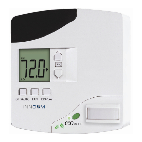
e528 Smart Digital Thermostat
Product Guide
Global Leader in Integrated Room Automation Systems
Copyright © 2010 INNCOM
Figure 1 e528 Digital Thermostat
Advertisement
Table of Contents

Related Manuals for Inncom e528

Summary of Contents for Inncom e528
- Page 1 Infrared (IR) or radio frequency (RF) transceiver and Passive Infrared (PIR) motion detector. The e528 interfaces with all common HVAC unit voltage configurations (24 volt to 277 volt). The e528 can be installed in a wired or wireless INNCOM guestroom control system, which makes installation feasible and affordable in either new construction or retrofit installations.
-
Page 2: Wireless Communication
TCT (an Ethernet gateway device). RF networking is possible with radio equipped models. The e528 features a guest-friendly graphic interface with intuitive controls (Figure 2). A user guide for the e528, written primarily for installers and facility management personnel, is available (see References below). -
Page 3: Installation Requirements
Installation Requirements Location: The e528 must be located on a partitioning interior wall, approximately 1.5 m (5 ft) above the floor, in a site of average temperature. It is important to ensure that the thermostat is located away from direct sunlight or radiant heat, air discharge grills, stairwells, outside doors, steam or water pipes, warm air stacks, unheated/uncooled areas, or sources of electrical or radio interference. - Page 4 Mounting: The e528 is usually mounted on a standard double-gang (4 x 4) junction box. If mounted on a single- gang box, the left side (display side) of the e528 overlaps the wall area to the left of the junction box. A low- voltage mounting plate, mud ring, or low-voltage caddy may be used for mounting 24 volt applications.
- Page 5 E 5 2 8 P r o d u c t G u i d e P a g e 5 o f 1 8 Figure 5 Back View Showing Headers and Sockets...
- Page 6 External temperature control sensor: This header accepts the wiring harness from an external temperature probe that can be used to supply the e528 with remote temperature measurements. The e528 uses a 10K 1% thermistor for external temperature measurement. This external temperature sensor can be used to monitor room temperature at a different location from where the e528 is mounted or to monitor pipe water temperature.
- Page 7 E 5 2 8 P r o d u c t G u i d e P a g e 7 o f 1 8 Connect the harness H2 (black) of 203-251 to the RS485 header of the e528.4G •...
- Page 8 P a g e 8 o f 1 8 E528.4G Retrofit Installation The e528.4G can be used to retrofit an application where a legacy e528 was used. Follow the procedure below: 4G to 2G Standalone application: with/without door switch input (no backhaul network) Using the adapter (P/N 203-013) connect the harness from the wall box (P/N 62-1462) previously •...
- Page 9 Plug the pre-wired 10-pin connector into the female receptacle at the back of the e528. Hook the tabs at the top rear of the e528 housing into the matching depressions at the top of the mounting plate and rotate the bottom of the housing toward the wall until it snaps into place on the mounting plate.
- Page 10 INNCOM ES-1 Flash Memory Module. The ES-1 provides the ability to copy HVAC related parameter settings from a “golden” e528 that has previously been installed in a room and had its HVAC related parameters set correctly and verified operationally with the HVAC equipment. Once these settings are copied to the ES-1 module, plugging the ES-1 into a new thermostat automatically uploads the settings.
-
Page 11: Load Specifications
The following load specification table (Table 6) describes the submitted load characteristics for testing and UL certification of UL 873. The device complies with the requirements of CAN/CSA C22.2 No. 24-93. Table 6. Load Specifications MODEL e528-A2L2-I0P0- e528-A3L2-I0P0- e528-A1L2- e528-B0L2-... -
Page 12: Technical Specifications
P a g e 1 2 o f 1 8 Technical Specifications Table 7. Technical Specifications Power Requirements 24 VAC at 50/60 Hz, 24 VDC nominal, 2.4 VA (e528-3xx/7xx and e528-4xx) 100 to 277 VAC at 50/60 Hz, 2.4 VA (e528-8xx) Relay Contact Rating See Table 4. -
Page 13: Ordering Specifications
Figure 9 IR Only E528.2G OPN Scheme The “X” number is the first of the three digits and designates the power supply type Table 8. IR only e528 Power Supply Ordering Power Supply Type 12VDC S5BUS (Power Supply removed, powered by external X06 or X05... - Page 14 For the RF capable thermostats, the complexity engendered by the multiplicity of power supplies, logic boards, and communications and other option call for a larger OPN incorporating a more granular scheme (Figure 13, below). Table 9 lists the options available for the RF E528: Figure 10 e528 3G OPN Figure 11 RF Capable e528 OPN Table 9.
- Page 15 E 5 2 8 P r o d u c t G u i d e P a g e 1 5 o f 1 8 Power Supply This character set defines the power supply options available for the e528. OP/N Code Power Supply Type...
- Page 16 E 5 2 8 P r o d u c t G u i d e P a g e 1 6 o f 1 8 OP/N Code Motion Detection/Output Type Part Number Flat PIR 02-9499 DND/MUR only 53-0448 Manual heat/cool selection only ecoMODE only 53-9209 Standard PIR with DND/MUR...
- Page 17 Custom Ordering Example: e528-A1-L2-I5-P2-1-O-WH = An e528 with a 24VAC 50/60Hz power supply (300 series), 64K logic board, IR5 auxiliary communication device, flat PIR motion detector, humidity sensor, no logo, manufactured in white. Figure 14 indicates the area of the thermostat that has options VISIBLE to the guest.
-
Page 18: Document Revision History
P a g e 1 8 o f 1 8 Figure 12 Area of Thermostat with Options Visible to the Guest References e528 Operation Manual, INNCOM Document 3000, Version 2.0, Dated April 29, 2005 Document Revision History REVISION DATE ISSUED...
Need help?
Do you have a question about the e528 and is the answer not in the manual?
Questions and answers