Table of Contents
Advertisement
Advertisement
Table of Contents

Related Manuals for Voltech ISC3020


Summary of Contents for Voltech ISC3020
- Page 1 Installation and Operating Instructions Solar System Controller ISC3020...
- Page 3 And pass then on to any future owner or user of this product. This manual describes the installation, function, operation and maintenance of the solar system controller ISC3020. These operating instructions are intended for end customers. A technical expert must be consulted in cases of uncertainty.
- Page 4 Caution Users should seek advice if any of the following situations occur: The solar charge controller does not appear to function at all. The solar charge controller or connected cables are visibly damaged. Emission of smoke or fluid penetration. ...
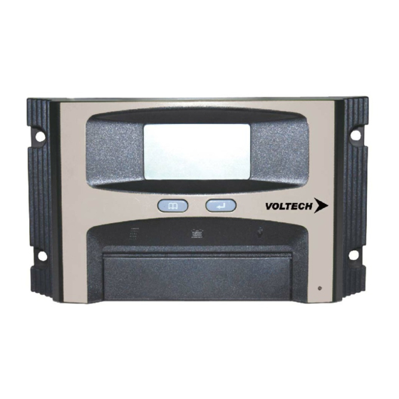
- Page 5 2. Display window Change the display windows with the “Menu” button; (e.g. for 12V battery) 1. The default window will show like below, battery voltage/capacity volume of the battery. Press “menu” button once to check charging current. 3. Press” menu” button again to display the load current. 4.
- Page 6 The set points of the deep discharging protection are predefined and cannot be reset. 3. Temperature Compensation ISC3020 has an internal ambient temperature sensor that compensates during the float mode. INSTALLATION Install the controller in a ventilated area away from flammable materials and gases.
- Page 7 WARNING ISC3020 can work with input voltage up to 45 Vdc maximum; when installing at this voltage, particularly with regard to module open circuit voltage (Voc), the entire solar energy system must be installed with protection class II. Cover solar modules during installation and use only insulated tools.
- Page 8 Battery over voltage shutdown GROUNDING Grounding ISC3020 is not technically required when installing a stand alone solar system. However, if required, Common grounding of the negative Battery and Load control output is OK (for negative earth electrical systems such as a caravan or motor-home).
- Page 9 MAINTENANCE The controller is maintenance-free. We strong suggest that all components of the PV system must be checked at least annually, Ensure adequate ventilation of the unit Check the cable strain relief Check that all cable connections are secure Tighten screws if necessary Terminal corrosion ERROR MESSAGES Caution! Please do not open the controller or attempt to replace components when troubleshooting.
- Page 10 Meaning: Over current at the load output. Remedy: 1) Reduce load current to <30Amps.. 2) If reducing load current does not work; Press “Enter” button. If LCD shows E4 with NO load connected or, LCD shows current as 0.00A. WITH a load of more than 50Watts running, Then follow the Reset Procedure as follows;...
- Page 11 The Leading Edge in Solar Technology Waste electrical products should not be disposed of with household waste Please recycle where facilities exist Check with your local authority or retailer for recycling advice Specifications are subject to change without prior notice Copyright reserved by Electro Parts Australia Pty Ltd Instruction manual Ver.
Need help?
Do you have a question about the ISC3020 and is the answer not in the manual?
Questions and answers