
Subscribe to Our Youtube Channel
Related Manuals for Phabrix PHABRIX Rx


Summary of Contents for Phabrix PHABRIX Rx
- Page 1 ® PHABRIX® broadcast excellence PHABRIX Rx Operation Manual Software Release 0.03.0015 Manual Revision 2 PHRX2000-200 2 Copyright © PHABRIX Ltd 2012...
-
Page 2: About This Manual
About this Manual Notice The information in this document has been produced by PHABRIX Ltd with care and is believed to be accurate. PHABRIX Ltd does not assume responsibility for loss or damage resulting from errors, omissions or inaccuracies herein. This document is subject to change and revisions may be made and issued to include such changes. -
Page 3: Getting Started
100 and 240VAC at 50-60Hz. Only the supplied power adaptor should be used with the unit. Do not use a damaged AC cable with the unit as it may cause a shock or fire hazard. Replacement AC cables are available from your local PHABRIX agent. PHRX2000-200 2... - Page 4 Installation Environment Operating Temperature The unit should only be operated between 0 and 40 °Centigrade. If the unit is operated at a higher temperature there is a possibility of a fire hazard. If the temperature is changed rapidly from a cold environment to a hot environment, moisture can be created internally which can cause malfunction or damage the unit.
- Page 5 3G-SDI and advanced formats upgrade for Rx chassis ........... 1–11 HD/SD-SDI Data Analyzer and Ancillary Packet analyzer ........1–11 Dolby - E analysis ....................1–12 Dual analyzer for SDI input modules ..............1–12 Advanced physical layer analysis ................1–12 PHRX2000-200 2 PHABRIX Rx Operation Manual...
-
Page 6: Table Of Contents
Front Panel Control 1–13 1–13 Rx2000 ........................Turning on and off the instrument ................1–13 Main Menu ......................1–13 Instrument Status ....................1–14 Using the Menus ....................1–14 Multiple Analyzers ....................1–15 Rx1000 & Rx500 ....................... 1–16 Turning on and off the instrument ................1–16 Navigation ...................... - Page 7 Setup Button Dialogue ................... 2–19 Vectorscope ......................... 2–20 Eye ..........................2–21 Eye Display ......................2–22 Jitter Filters ......................2–23 Jitter Meter Ranges ....................2–23 Setup ........................2–24 Advanced Jitter Analysis (Option)................2–25 Jitter ........................... 2–26 PHRX2000-200 2 PHABRIX Rx Operation Manual...
- Page 8 Signal Information Menu 2–27 Overview ........................2–27 Video Status ........................ 2–27 EDH/CRC ERRORS ....................2–27 EDH DATA ......................2–27 Cable Length ......................2–28 Active Picture CRC ....................2–28 MISC Status ........................ 2–29 Payload ID – SMPTE 352 ..................2–29 Video Format ......................2–29 Video Timing .......................
- Page 9 Log Time Limit ......................2–55 Log Eye Jitter ......................2–56 Jitter Thresholds ....................2–56 Eye Timings ......................2–56 Eye Amplitude ......................2–56 Log ANC Status ......................2–57 Speaker Menu 2–59 Overview ........................2–59 Glossary Glossary of Terms A–3 PHRX2000-200 2 PHABRIX Rx Operation Manual...
- Page 10 Specification Rx Platform B–3 Overview ........................B–3 Rx2000 B–5 Description .........................B–5 Description ......................B–5 Environmental Requirements ..................B–5 Dimensions .........................B–6 Front Panel Dimensions ..................B–6 Back Panel Dimensions ..................B–6 Top Panel Dimensions .....................B–6 Side Panel Dimensions ...................B–6 Front Panel .........................B–7 Front Panel Display ....................B–7 Loud Speakers .......................B–7 Headphone Output ....................B–7 Rear Panel...
- Page 11 Analyzer Optical Input ....................B–29 Generator Optical Output ..................B–29 Generator Functionality ..................B–30 Analyzer Functionality ....................B–30 Single/Dual Analyzer, Dual Input, Physical Layer Measurement ........B–31 Analyzer SDI Inputs ....................B–31 Analyzer SDI Outputs .....................B–31 Analyzer Optical Inputs ..................B–31 Analyzer Functionality ....................B–32 PHRX2000-200 2 PHABRIX Rx Operation Manual...
- Page 12 Dual Output Generator Module ..................B–33 Generator Optical Outputs ..................B–33 Generator Functionality ..................B–33 Supported Video Formats B–35 SD 270 Mb/s ......................B–35 HD 1.485 Gb/s (SMPTE 292M) ..................B–35 Dual Link 1.485 Gb/s (SMPTE 327M) .................B–36 3G Level-A 2.97 Gb/s (SMPTE 425M-A) ..............B–38 3G Level-B 2.97 Gb/s (SMPTE 425-B) .................B–39 Built-in Generator Formats (CPU Module)
- Page 13 ® Description PHABRIX® broadcast excellence PHRX2000-200 2 PHABRIX Rx Operation Manual 1–1...
- Page 14 1–2 Description 08/12 PHRX2000-200 2...
-
Page 15: Rx Platform
The ‘Rx platform’ has been designed to serve the varied test and measurement needs of the broadcast industry. PHABRIX has developed not a single product in the traditional sense but a modular system from which specific broadcast client requirements can be satisfied. -
Page 16: Rx2000
Rx2000 Description The Rx2000 is a 2U rack mounted instrument that provides the following: Two front panel TFT screens, one to display the selected input image and the other to display the generator and analyzer menus and selected analyzer instrument panels such as Waveform monitor, Vectorscope and Eye Pattern display. -
Page 17: Rx1000 Rasteriser
The power for the Rx instrument is provided by a separate PSU unit that connects to the 4-pin male XLR connector at the left of the instrument. Specifications See Appendix B for specifications PHRX2000-200 2 PHABRIX Rx Operation Manual 1–5... -
Page 18: Rx500 Rasteriser
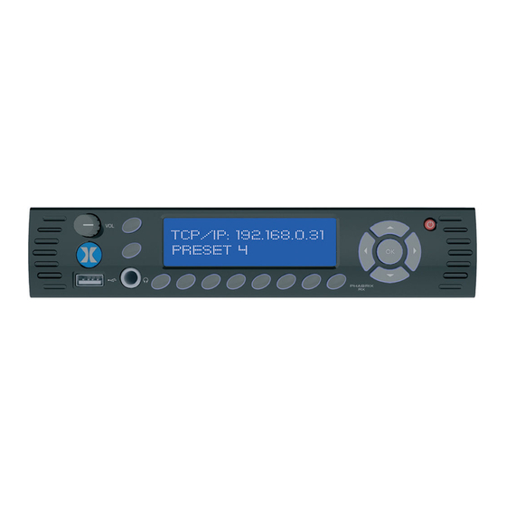
Rx500 Rasteriser Description The Rx500 is a 1U, half rack width instrument (available with optional rack mount kit) that provides the following: OLED display to allow the monitoring inputs and the selection of Monitor display, Analyzer and Generator presets. Rasterised HDMI/SDI outputs to allow up to 16 individual instrument panels (windows) to be displayed on a single DVI 1920 x 1080 resolution monitor. -
Page 19: Rx Modules
‘competitive tender’ requirements. Dual USB ports are provided for mouse and keyboard control. Ethernet provides remote access via web browser and is also the method for updating firmware and software from PHABRIX’s dedicated server. -
Page 20: Single Analyzer, Dual Input
Longitudinal Timecode (LTC) - Receive (RX) P (RS-422 compatible) Longitudinal Timecode (LTC) - Receive (RX) N (RS-422 compatible) Audio Line Out - Right (1V peak-to-peak analogue audio, full scale 0dBFS) Audio Line Out - Left (1V peak-to-peak analogue audio, full scale 0dBFS) 5 Volt, current-limted GPIO supply for ‘open drain’... -
Page 21: Single Analyzer, Single Generator
Only single transmitter, single reciever modules that are compliant to SMPTE 424M, SMPTE 292M, and SMPTE 259M are supported. GEN - provides a test signal generated by the PHRXM-AG module. ANA - allows the Rx instrument to analyse the connected input. PHRX2000-200 2 PHABRIX Rx Operation Manual 1–9... -
Page 22: Dual Output Generator Module
Dual Output Generator Module The PHRXM-GG module allows the OPTICAL OPTICAL generation of a two independent SDI or Optical video test signals with the same video format, colour space and frame rate GEN-B GEN-A GEN-B GEN-A GEN-B GEN-A GEN-B GEN-A for Dual link use. -
Page 23: Rx Software Options
‘user defined’ selections with the appropriate DID or SDID code. Access to the SDI analysis functionality is via the Analyzer - Signal Data menu. See the “Analyzer - Signal Data” section in chapter 2 for full details. PHRX2000-200 2 PHABRIX Rx Operation Manual 1–11... -
Page 24: Dolby - E Analysis
PHRXM-AG and PHRXM-AGE modules. Advanced physical layer analysis The analysis option (PHRXO-EA) for the PHABRIX Rx range adds an additional jitter screen, plus enhancements to the eye display. The extra features added to the eye and jitter module are focussed toward broadcast manufacturers who have a need for high end analysis tools. -
Page 25: Front Panel Control
Front Panel Control Rx2000 Turning on and off the instrument To turn on your PHABRIX Rx2000 press the red button at the top right hand corner of the front panel. Volume Power Confidence Display Input Selection Buttons Menu Selection Buttons... -
Page 26: Instrument Status
Instrument Status The top line of the menus shows the instrument status and includes the Input Video status, Genlock status and current time. A red “Log” is shown on the status line if there are any events in the event log. If a 3G video standard is selected the video standard display will be shown as 3GA if it is a 3G-Level A standard, 3GB if it is a 3G-Level B dual link standard, 3G2 if it is a 3G-level B dual stream (two patterns) standard or DL if it is a dual link output. -
Page 27: Multiple Analyzers
Fld 1 Fld 1 YCbCr Blue Zoom 100% All of the different Instrument displays (Picture, Waveform Monitor, Vectorscope, etc) will use Analyzer 1. The front panel buttons will just switch the instrument being displayed. PHRX2000-200 2 PHABRIX Rx Operation Manual 1–15... -
Page 28: Rx1000 & Rx500
Rx1000 & Rx500 Turning on and off the instrument To turn on your PHABRIX Rx1000 or Rx500 instrument, press the button at the top right hand corner of the front panel. Once the system has started, pressing the button again will turn it off. If for some reason the instrument stops responding, pressing and holding the button for a few seconds will turn it off. - Page 29 Rx500 instrument. Remote Control allows the Rx remote control to be turned on or off. The six buttons below the LED display control the selection of the options within the currently selected menu. PHRX2000-200 2 PHABRIX Rx Operation Manual 1–17...
- Page 30 1–18 Description 08/12 PHRX2000-200 2...
-
Page 31: Monitor Output
The instrument panels that are display can be selected from pre-configured, already saved and/or New instrument panels (or windows) created by right-clicking using the mouse. PHRX2000-200 2 PHABRIX Rx Operation Manual 1–19... -
Page 32: Window Panel Types
Window Panel Types The types of instrument panels that are available include: New Picture Selecting New Picture will A : 1 SDI1 Picture create a new Picture panel for the selected input. Line Sample Fld 1 Blue Note that black “A : 1” in the top left corner is used to select the Analyzer to use, the black “SDI#”... -
Page 33: New Vectorscope
Jitter monitor panel for the selected input. This allows the jitter of the selected input video signal to be monitored against time. See the “Analyzer” - “Jitter” section in chapter 2 for details. PHRX2000-200 2 PHABRIX Rx Operation Manual 1–21... -
Page 34: New Sdi Errors
New SDI Errors Selecting New SDI Errors will display the EDH or CRC status of the analyzer input as appropriate for the video standard being monitored. The status of each EDH/ CRC count is displayed as the number of seconds since an error occurred. -
Page 35: New Data View
RP165 – EDH, S272 – SD Audio Group 1, S272 – SD Audio Group 2, etc) for the selected SDI input. See the “Sys Info” -“Ancillary Inspector” section in chapter 2 for information. PHRX2000-200 2 PHABRIX Rx Operation Manual 1–23... -
Page 36: New Audio Meters
New Audio Meters Selecting New Audio Meters will create a new panel displaying the audio metering for the selected audio input. This page shows up to 16 audio channels. The source for each block of 8 meters may be independently set to allow simultaneous metering of 8 inputs and 8 outputs or all 16 channels... -
Page 37: New Generator
Audio 5-8 will create a new Generator Audio panel to allow a test signal to be setup for Audio Groups 3 and 4. See the “Generator” - “Audio Group 3/4” section in chapter 2 for details. PHRX2000-200 2 PHABRIX Rx Operation Manual 1–25... -
Page 38: New Generator Reference
New Generator Reference Selecting New Generator Reference will create a new Generator Reference panel to allow the Audio reference mode to be setup. See the “Generator” - “Gen Lock” section in chapter 2 for details. New Event Log Selecting New Event Log will create a new panel displaying the log results for any events (that have... -
Page 39: New Eye Log Setup
IP address displayed in the bottom right of the Monitor Output display. See the System - Network section in chapter 2 for details. PHRX2000-200 2 PHABRIX Rx Operation Manual 1–27... -
Page 40: System Info
System Info Selecting System Info will display the system software status and options that are installed. Note also that this menu can also be displayed by clicking on the software version displayed in the bottom right of the Monitor Output display. See the System - Misc section in chapter 2 for details. -
Page 41: Hdmi/Cpu Sdi Setup
“Set User Login Information” menu in a new window. This can be used to manage user access to the Rx instrument. See the “System”-”Engineer” section in chapter 2 for details. PHRX2000-200 2 PHABRIX Rx Operation Manual 1–29... -
Page 42: Managing The Monitor Output
Managing the Monitor Output Closing Open Panels (Windows) Any open panels can be closed using the “X” button in the top right corner of each panel. The currently selected panel (the one with the blue bar) can be closed by right-clicking the mouse in the display area above the “Input Status Bar”... -
Page 43: Working With Multiple Generators
The “System Presets” panel then allows “HDMI Layout” check box to be chosen, a name given to the preset before it is saved. Stored presets can then be recalled at a later time. See the “Presets” section for details. PHRX2000-200 2 PHABRIX Rx Operation Manual 1–31... - Page 44 1–32 Description 08/12 PHRX2000-200 2...
-
Page 45: Browser Control
The “Downloads” link displays a further page allowing screen dumps and report files (Command script option) to be viewed. PHRX2000-200 2 PHABRIX Rx Operation Manual 1–33... -
Page 46: Using The Menus
Using the Menus The Menu buttons select which instrument is in use as well as selecting the options for the instrument. The bottom of the LCD display shows the function of each Menu button. When in a specific function eg Generator, Analyzer etc, the cursor controls () on the right hand of the instrument select a field to edit. -
Page 47: Phrx2000-200 2
® PHABRIX® Menu Reference broadcast excellence PHRX2000-200 2 PHABRIX Rx Operation Manual 2–1... - Page 48 2–2 Menu Reference 08/12 PHRX2000-200 2...
-
Page 49: Generator Menu
Option may be purchased to enable other colour formats. The following colour modes may be selected dependent on line standard selected: YCbCr 422 10bit YCbCr 444 12bit YCbCr 444 10bit YCbCrA 4444 10bit YCbCr 422 12bit RGB 444 10bit RGBA 4444 10bit RGB 444 12bit PHRX2000-200 2 PHABRIX Rx Operation Manual 2–3... -
Page 50: Pattern
Zone plate vertical Bars – 3 variants Black, Red, Green, Downloadable files Blue, Yellow, Cyan, in bitmap(.bmp), Magenta, White, 10bit DPX/YUV (.dpx, Custom .yuv), Targa (.tga) and Phabrix .pat/.rgb/.yc4 Colour Field compressed files User File 2–4 Menu Reference 08/12 PHRX2000-200 2... - Page 51 It is specified in degrees per frame. Angle - changes the angle of the zone plate and thus can change a horizontal sweep into a vertical sweep or rotate an elliptical zone plate pattern. PHRX2000-200 2 PHABRIX Rx Operation Manual 2–5...
-
Page 52: Edh
XScale/Start Freq - sets the horizontal scale of grating patterns or the start value of the zone plate sweep frequency. YScale/End Freq - sets the vertical scale of grating patterns or the end value of the zone plate sweep frequency. If the output signal is SD (PAL-625 or NTSC-525) the insertion of EDH information may be turned on or off. -
Page 53: Genlock Menu
The generator may be locked to an input reference which may be either the reference input which is a Bi-Level/Tri-Level sync or may be locked to the video input. Alternatively, the generator may free run. PHRX2000-200 2 PHABRIX Rx Operation Manual 2–7... -
Page 54: Audio Group Menu
Audio Group Menu The Rx instrument can embed an audio signal on all 16 embedded audio outputs. The Audio Group menu controls which audio channels, pairs or groups have test tones applied and the type of tone. Group n Each of the four groups may be separately enabled. When enabled, the source and level of each channel in a pair can be selected. -
Page 55: Dolby
The most elaborate mode in common use is Dolby 7.1 which uses all eight channels to provide surround sound. PHRX2000-200 2 PHABRIX Rx Operation Manual 2–9... -
Page 56: Dolby Synchronisation - Generator Reference
Dolby Synchronisation - Generator Reference The Dolby audio test signal produced by the Rx instrument is affected by the use of a reference signal connected to the Rx instrument and by the following settings: Free Run - If the generator is not locked to reference, the Dolby signal will be generated synchronous to the generator. -
Page 57: Program Meta Data Editing
Dolby 7.1 Dependent Substream. LR CtrDnMix (left/right/centre down-mix) is a weighting value used in the encoding and decoding of surround sound mixes for a Dolby 5.1 Independent Substream. PHRX2000-200 2 PHABRIX Rx Operation Manual 2–11... - Page 58 LR SurDnMix (left/right/surround down-mix) is a weighting value used in the encoding and decoding of surround sound mixes for a Dolby 5.1 Independent Substream. Chan Mode defines the channel configuration for Program 1 (ie mono, stereo, 5.1 channels). Line Mode this is an Operational Mode / Dynamic Compression Mode that is used by consumer and professional decoder products that simplifies the implementation of Dialogue Normalization, Dynamic Range Control, and...
-
Page 59: Default Program Meta Data
To embed Dolby signals on the AES output, the Audio source for the AES output should be set to ‘Dolby’ . This selection is found on the right hand side of the Generator – Audio Group 1,2,3,4 pages. PHRX2000-200 2 PHABRIX Rx Operation Manual 2–13... - Page 60 2–14 Menu Reference 08/12 PHRX2000-200 2...
-
Page 61: Analyzer Menu
Signal Data page, the cursor will show where that is on the ‘Full Picture’ page. The different types of analyzer can be displayed on the front panel of the Rx2000 instrument and as window panels on the HDMI monitor output. PHRX2000-200 2 PHABRIX Rx Operation Manual 2–15... -
Page 62: Picture
Picture With Picture selected, the video picture is displayed in a window as a down- converted display. The picture will automatically view the horizontal or vertical blanking areas if the line or sample values are in the blanking area. From the Rx2000 front panel, if the focus cursor is moved to the picture window and OK pressed, the cursor may be used to scroll around the window. -
Page 63: Signal Data
YCbCr values are packed into 10 bit values across the different streams and thus will give unfamiliar values. When the ‘UnPack’ check box is checked the values in the active picture are unpacked to RGB or YCbCr values. PHRX2000-200 2 PHABRIX Rx Operation Manual 2–17... -
Page 64: Waveform Monitor
Waveform Monitor The Waveform menu displays the selected input in the form of a waveform monitor. The display may be restricted to a single line or all lines may be displayed at the same time. The display can be formatted as all streams (Luma and Chroma) or just a single stream. -
Page 65: Cursors
The axes and measurements for the waveform monitor can be displayed either in percentages or in hex or decimal values as required. Horizontal Scale: The timing measurements may be set in either pixels or micro-seconds (us) PHRX2000-200 2 PHABRIX Rx Operation Manual 2–19... -
Page 66: Vectorscope
Vectorscope The Vectorscope menu displays the selected input in the form of a vectorscope. This may be set to show either the 100% bar positions or 75% positions. The colour bar position boxes will change according to the colour space for the current input video standard. -
Page 67: Eye
Alignment Jitter which cause decoding errors due to incorrect sampling of the data stream because the SDI Clock transition occurs on the edge of the data sample instead of in the centre of the data sample. PHRX2000-200 2 PHABRIX Rx Operation Manual 2–21... -
Page 68: Eye Display
Wander refers to a long-term time interval error, ie artefacts below 10 Hz. Typically all video equipment has the tendency to cause wander over a long period, the display of these artefacts are not easily displayed in a meaningful way but are better logged as errors that exceed tolerances over a long period. -
Page 69: Jitter Filters
0.52UI 0.34UI 0.34UI Full-Scale Alignment 0.3UI 0.2UI 0.2UI (Red Threshold) Alignment 0.2UI 0.14UI 0.14UI (Yellow Threshold) Timing 3.4 UI 1.7UI 0.34UI Full Scale Timing 0.2UI (Red Threshold) Timing 1.4UI 0.7UI 0.14UI (Yellow Threshold) PHRX2000-200 2 PHABRIX Rx Operation Manual 2–23... -
Page 70: Setup
Setup The Setup button shows a dialogue box that allows the eye colour and cable type to be specified. Cable Type Selects the cable type used which affects the cable measurements. B8281 Belden 8281 B1505 Belden 1505 B1694A Belden 1694A B1855A Belden 1855A CL5CSB... -
Page 71: Advanced Jitter Analysis (Option)
Adjusts the number of eyes visible on the eye display. The 10 and 20 modes are useful for observing serial-parallel conversion jitter, the H, 2H, V, and 2V are useful for observing the effects of power supply born video synchronous noise in SDI signals. (H/2H/V/2V not yet implemented) PHRX2000-200 2 PHABRIX Rx Operation Manual 2–25... -
Page 72: Jitter
Jitter The Advanced Analysis package provides a jitter display. This screen shows a trace of jitter amplitude versus time along with two jitter thermometers and has the following controls: Jitter-1: Timing/Align/10Hz/100Hz/1KHz/10KHz/100KHz. This filter operates on both the left hand jitter thermometer and the jitter trace. Jitter-2: Timing/Align/10Hz/100Hz/1KHz/10KHz/100KHz. -
Page 73: Signal Information Menu
Eda: Error Detected Already - This is set to 1 if a SDI error was detected in the signal received by the previous device. Idh: Internal error Detected Here - This is set to 1 if a hardware error was detected in the previous device. PHRX2000-200 2 PHABRIX Rx Operation Manual 2–27... -
Page 74: Cable Length
Ida: Internal error Detected Already - This is set to 1 if an idh flag was received by the previous device. Ues: unknown error status: This is set to 1 if the previous device received an SDI signal from a device not supporting EDH. -
Page 75: Misc Status
“Invalid” but the values in this section will be updated every few seconds. The Re-sync counter displays the number of times the SDI data has been re-synchronised and can help detect intermittent SDI signal problems. PHRX2000-200 2 PHABRIX Rx Operation Manual 2–29... -
Page 76: Video Timing
Video Timing The Video Timing menu displays the relationship between the selected video input with respect to the locking reference input. The timing of SDI input signals is displayed relative to the external reference. If no reference is present then an error message is displayed. If the signal is timed to within +/- 2 samples the values are displayed in black in lines and samples (spl) If mis-timed, then they will be displayed in red. -
Page 77: Anc Status (Anc Option)
The packet name, data ID (DID) and SDID may be specified for up to 3 user-defined ancillary packets. The stream field specifies whether the packet should be on the chroma stream, the luminance stream or both. PHRX2000-200 2 PHABRIX Rx Operation Manual 2–31... -
Page 78: Anc Inspector (Sdi Data Option)
ANC Inspector (SDI Data Option) The SDI Data Option allows Ancillary data packets to be detected and checked for errors. The ANC Inspector menu displays details of the ANC packets. The packet type can be selected using either the drop down list of known packets or the DID/ SDID number fields. -
Page 79: Anc Inspector Setup
The Setup dialogue also shows when an ANC packet has been detected and where it was found. This makes changing a filter simpler as the effect of the filter can be determined without closing the dialogue. This dialogue also allows the user defined ANC packets to be configured. PHRX2000-200 2 PHABRIX Rx Operation Manual 2–33... - Page 80 2–34 Menu Reference 08/12 PHRX2000-200 2...
-
Page 81: Audio Menu
Dolby levels for the specified audio pair or AES input. Note that Dolby audio cannot be heard on the speaker as a Dolby decoder is not present. PHRX2000-200 2 PHABRIX Rx Operation Manual 2–35... -
Page 82: Audio Status
Audio Status The Audio Status menu shows the Channel Status for the selected audio channel is displayed in decoded form as well as a hexadecimal dump of the bytes. The source may either come from the input signal or from the generator for comparison purposes. -
Page 83: Dolby-E Status (Dolby-E Analyzer Option)
The most elaborate mode in common use is Dolby 7.1 which uses all eight channels to provide surround sound. PHRX2000-200 2 PHABRIX Rx Operation Manual 2–37... -
Page 84: Analyser Reference
Analyser Reference In order for the Dolby-E data to be decoded correctly, the internal audio circuitry requires a reference that is synchronized to the input signal. The Generator Reference MUST therefore NOT be set to Free-Run or Dolby-E errors may be detected. The description field will display “Invalid Reference”... -
Page 85: Programme Configuration
Program selection: Selects which set of program meta-data is shown. Up to 8 programs can be encoded in the Dolby-E packet dependent on the Program Configuration. User defined description for the selected program. Program description PHRX2000-200 2 PHABRIX Rx Operation Manual 2–39... -
Page 86: Programme Metadata
Programme Metadata The “Audio” – “Dolby” menu allows the metadata for a Dolby E data stream to viewed. For any programme this metadata would be created as part of Dolby E authoring process. The following metadata can be viewed for Program 1: Dialogue Norm is the normal audio level for dialogue. -
Page 87: Peak Metering
NOT be able to listen to the Dolby-E signal. Note also that the LFE channel audio levels do not seem to be metered by current Dolby encoding modules. See the logging section for details on which changes of Dolby-E status may be logged. PHRX2000-200 2 PHABRIX Rx Operation Manual 2–41... - Page 88 2–42 Menu Reference 08/12 PHRX2000-200 2...
-
Page 89: System Menu
‘Back Space’ key will delete the key to the left of the cursor. The ‘Cancel’ key will cancel edit mode and restore the original text. Once you have finished editing the name, press ‘OK’ to rename the memory. PHRX2000-200 2 PHABRIX Rx Operation Manual 2–43... -
Page 90: Adding Additional Memories
Adding Additional Memories To add a new memory, press the ADD button. This will use the current memory name and settings. Clearing Memories Select the memory to be cleared by moving the cursor to the ‘Select Memory’ list and pressing ‘OK’... -
Page 91: Network
Network PHABRIX Rx is fully network compatible and has a complete network interface to allow control of any Rx instrument from any other unit. The Network menu allows the Rx instrument to be configured as part of a network. On all Rx instruments the network addressing can be setup using the HDMI monitor output. -
Page 92: Misc
Misc The Misc menu shows serial numbers, Rx instrument MAC address, version information and battery state. It also allows the date and time to be set and factory default settings to be recalled. The options security code is entered on this page if options are purchased. -
Page 93: Utils
If the error count is greater than 0, contact you local dealer for advice. System Temperature This section of the menu displays the current Rx instrument temperature. This information is provided for diagnostics purposes only. PHRX2000-200 2 PHABRIX Rx Operation Manual 2–47... -
Page 94: Voltages
Voltages This section of the menu displays the current voltages for the currently selected board in the “Board” section of the menu. This information is provided for diagnostics purposes only. This section of the menu displays the type of SFP (Small Form Factor Package) module is installed in the board currently selected board in the “Board”... -
Page 95: Engineer
Once the password is 6 characters or longer, the “Add User” button will become enabled and may be pressed. Make sure that your password is memorable. If all passwords to an Rx instrument are forgotten, you can contact Phabrix for an over-ride password. Users with administrator permission may add/delete users. -
Page 96: Editing The Prompt Text
Pressing the Download button will cause the current release of software to be downloaded from the Phabrix Web Site. This will take a short time dependent on the connection to the Internet. Once the download has completed, the software will be checked for errors before being stored on the Rx instrument for future installation. - Page 97 They can be restored from the System-Memories page using the Restore button and selecting the ‘_Before_Upgrade’ archive. The software release notes can be viewed by selecting the Changes button. PHRX2000-200 2 PHABRIX Rx Operation Manual 2–51...
-
Page 98: Hdmi/Sdi Output
HDMI/SDI Output The HDMI/SDI Outputs menu controls the use of the HDMI monitor output and the SDI output on the CPU module. The Rx range of products provide a Monitor output in the form of an HDMI output that can display up to 16 instrument windows at 1920 x 1080 resolution. -
Page 99: Logging Menu
Note that the event log only shows changes in status, so if the input is always in error and never good, an event will not be shown. To get the full state of the instrument will require looking at the current status as well as the event log. PHRX2000-200 2 PHABRIX Rx Operation Manual 2–53... -
Page 100: Log Setup
Log Setup The Log Setup menu allows specific events to be tracked by the Rx instrument. The events to be logged are set up on this page by checking the appropriate ‘Log’ check boxes. Audio Thresholds This section allows the thresholds for audio events to be set. If the audio level for a channel is higher than that specified for the Clip or High fields for the number seconds specified then an event will be added to the event log. -
Page 101: Aes Status
Event Log if they happen. If you are having problems with your Rx instrument, checking this box can add events that can help PHABRIX determine the nature of the problem. Save saves the current event log to a text file in the currently specified language. -
Page 102: Log Eye Jitter
Log Eye Jitter This menu allows Eye Jitter events to be logged. The events to be logged are set up on this page by checking the appropriate ‘Log’ check boxes. Jitter Thresholds The jitter level at which an event is added may be set independently for each meter. (Only one meter provided as standard) This allows you to set the maximum allowed jitter level and then test for invalid values over a period of time. -
Page 103: Log Anc Status
This allows the user to define and name their own DID/SDID values for an ANC packet type. Reset Clears the state for all packet types and thus a packet that was displayed as previously in error is shown as OK. PHRX2000-200 2 PHABRIX Rx Operation Manual 2–57... - Page 104 2–58 Menu Reference 08/12 PHRX2000-200 2...
-
Page 105: Speaker Menu
Rx Generator. If this is NOT the case, ‘clicks’ will be heard on the speaker. Either connect the Rx instrument reference to the same reference as the SDI input source and set the Generator-GenLock source to Ref or set the genlock source to Input-1. PHRX2000-200 2 PHABRIX Rx Operation Manual 2–59... - Page 106 2–60 Menu Reference 08/12 PHRX2000-200 2...
- Page 107 ® PHABRIX® Glossary broadcast excellence PHRX2000-200 2 PHABRIX Rx Operation Manual A–1...
-
Page 108: Glossary
A–2 Glossary 08/12 PHRX2000-200 2... -
Page 109: Glossary Of Terms
Function Buttons these are the set of 8 buttons below the Instrument Display on the Sx and Rx Ranges that are used to select the Instrument Display menu options. General Purpose Input) PHRX2000-200 2 PHABRIX Rx Operation Manual A–3... - Page 110 Graticule this is the scale displayed on an oscilloscope, vector scope or waveform monitor that provides a visual indication of the signal amplitude, time base and phase relationship. HDMI (High-Definition Multimedia Interface) is a compact audio/video interface for transferring uncompressed digital audio/video data from a HDMI-compliant device (“the source”...
- Page 111 (Society of Motion Picture & Television Engineers) SMPTE RP211 Implementation of 24P, 25P and 30P Segmented Frames for 1920 x 1080 Production Format SMPTE 259M Implement a SMPTE 259M Serial Digital Interface Using SMPTE HOTLink™ and CY7C9235/9335 PHRX2000-200 2 PHABRIX Rx Operation Manual A–5...
- Page 112 SMPTE 260M Television - 1125/60 High-Definition Production System - Digital Representation and Bit-Parallel Interface SMPTE 274M High Definition (HD) Image Formats for Television Production SMPTE-276M Television - Transmission of AES-EBU Digital Audio Signals Over Coaxial Cable SMPTE 292M Bit-Serial Digital Interface for High-Definition Television Systems SMPTE 296M 1280 ×...
- Page 113 ® PHABRIX® Specification broadcast excellence PHRX2000-200 2 PHABRIX Rx Operation Manual B–1...
- Page 114 B–2 Specification 08/12 PHRX2000-200 2...
-
Page 115: Rx Platform
The ‘Rx platform’ has been designed to serve the varied test and measurement needs of the broadcast industry. PHABRIX has developed not a single product in the traditional sense but a modular system from which specific broadcast client requirements can be satisfied. - Page 116 B–4 Specification 08/12 PHRX2000-200 2...
-
Page 117: Rx2000
4 Module slots allowing the installation of Analyzer and Generator modules. Environmental Requirements Operating Temperature 0-40 °C Operating Humidity <85% RH (no condensation) Power Requirements AC 90-250V 50/60Hz 16W max Height 2U, 3.5inch, 8.8cm Width 19inch, 48.2cm Depth 5.9inch, 15cm Weight 4.19Ibs, 1.9kg PHRX2000-200 2 PHABRIX Rx Operation Manual B–5... -
Page 118: Dimensions
Dimensions Front Panel Dimensions 485mm Back Panel Dimensions ???mm Top Panel Dimensions Side Panel Dimensions 130 mm B–6 Specification 08/12 PHRX2000-200 2... -
Page 119: Front Panel
The rear panel provides the Rx instrument’s connections via the CPU module and the installed Analyzer or Generator modules. See the “Modules” section for details of the different modules. Power Connection Connector 4-pin XLR, Male Voltage 12V +/- 5% AC. DC Power adapter provided PHRX2000-200 2 PHABRIX Rx Operation Manual B–7... -
Page 120: External Locking Reference
External Locking Reference Label Input Signal Tri-level or Bi-Level (black burst) syncs 50/59.94/60Hz Connector Input Impedance 75 ohm terminated Input Return Loss >40dB to 6MHz (typical) Maximum Input voltage +/- 2V Specification Tri-level syncs (SMPTE274M and SMPTE296M) 600 mV pk-pk PAL Black Burst (ITU624-4/SMPTE318) 1V pk-pk, Composite NTSC (SMPTE 170M) 1V pk-pk AES Input... -
Page 121: Gpio - Terminal
19 (GPIO - 0), 20 (GPIO - 1), 21 (GPIO - 2), 22 (GPIO - 3), 23 (GPIO - 4), 24 (GPIO - 5), 25 (GPIO - 6), 26 (GPIO - 7) Purpose Not currently implemented. PHRX2000-200 2 PHABRIX Rx Operation Manual B–9... - Page 122 B–10 Specification 08/12 PHRX2000-200 2...
-
Page 123: Rx1000 Rasteriser
4 Module slots allowing the installation of Analyzer and Generator modules. Environmental Requirements Operating Temperature 0-40 °C Operating Humidity <85% RH (no condensation) Power Requirements AC 90-250V 50/60Hz 16W max Height 1U, 1.75inch, 4.4cm Width 19inch, 48.2cm Depth 6.7inch, 17cm Weight 3.75Ibs, 1.7kg PHRX2000-200 2 PHABRIX Rx Operation Manual B–11... -
Page 124: Dimensions
Dimensions Front Panel Dimensions 483mm Top Panel Dimensions Side Panel Dimensions 130 mm B–12 Specification 08/12 PHRX2000-200 2... -
Page 125: Front Panel
Input Return Loss >40dB to 6MHz (typical) Maximum Input voltage +/- 2V Specification Tri-level syncs (SMPTE274M and SMPTE296M) 600 mV pk-pk PAL Black Burst (ITU624-4/SMPTE318) 1V pk-pk, Composite NTSC (SMPTE 170M) 1V pk-pk PHRX2000-200 2 PHABRIX Rx Operation Manual B–13... -
Page 126: Aes Input
AES Input Label AES IN Connector Input Impedance 75 ohm terminated Maximum Input Voltage +/- 2V Sample Rates The input has a sample rate converter and so will accept any sample rate from 32kHz to 192kHz. Specification Conforming to AES3-2003 and SMPTE-276M SDI Out Label SDI OUT... -
Page 127: Gpio - Longitudinal Timecode (Ltc)
19 (GPIO - 0), 20 (GPIO - 1), 21 (GPIO - 2), 22 (GPIO - 3), 23 (GPIO - 4), 24 (GPIO - 5), 25 (GPIO - 6), 26 (GPIO - 7) Purpose Not currently implemented PHRX2000-200 2 PHABRIX Rx Operation Manual B–15... - Page 128 B–16 Specification 08/12 PHRX2000-200 2...
-
Page 129: Rx500 Rasteriser
Environmental Requirements Operating Temperature 0-40 °C Operating Humidity <85% RH (no condensation) Power Requirements AC 90-250V 50/60Hz 16W max Height 1U, 1.75inch, 4.4cm Width 8.5 inch, 24.1cm Depth 6.7inch, 17cm Weight 1.65Ibs, 0.75kg PHRX2000-200 2 PHABRIX Rx Operation Manual B–17... -
Page 130: Dimensions
Dimensions Front Panel Dimensions 223mm Top Panel Dimensions Side Panel Dimensions 164 mm B–18 Specification 08/12 PHRX2000-200 2... -
Page 131: Front Panel
Purpose allows the Rx instrument to be locked to a studio reference. Specification Tri-level syncs (SMPTE274M and SMPTE296M) 600 mV pk-pk PAL Black Burst (ITU624-4/SMPTE318) 1V pk-pk, Composite NTSC (SMPTE 170M) 1V pk-pk PHRX2000-200 2 PHABRIX Rx Operation Manual B–19... -
Page 132: Aes Input
AES Input Label AES IN Connector Input Impedance 75 ohm terminated Maximum Input Voltage +/- 2V Sample Rates The input has a sample rate converter and so will accept any sample rate from 32kHz to 192kHz. Specification Conforming to AES3-2003 and SMPTE-276M SDI Out Label SDI OUT... -
Page 133: Gpio - Longitudinal Timecode (Ltc)
19 (GPIO - 0), 20 (GPIO - 1), 21 (GPIO - 2), 22 (GPIO - 3), 23 (GPIO - 4), 24 (GPIO - 5), 25 (GPIO - 6), 26 (GPIO - 7) Purpose Not currently implemented PHRX2000-200 2 PHABRIX Rx Operation Manual B–21... - Page 134 B–22 Specification 08/12 PHRX2000-200 2...
-
Page 135: Rx Modules
Loop through of IN1 and IN2 Analyzer Optical Inputs Label OPTICAL A and B Type SFP Optical Dual Receiver Module (option PHRXM-OPTAA) Specifications SMPTE 424M, SMPTE 292M, and SMPTE 259M Purpose To provide 2 optical video/audio inputs PHRX2000-200 2 PHABRIX Rx Operation Manual B–23... -
Page 136: Analyzer Functionality
Analyzer Functionality The PHRXM-A module provides analyzer functionality for two concurrently connected SD-SDI, HD-SDI or Optical inputs. With the module installed the Analyzer menu (see chapter 2 for details) allows the follow monitoring to be displayed: The Picture viewer is provided to allow you to monitor the selected input to give confidence that the signal is present, is the correct subject (or feed), it is moving and looks OK. -
Page 137: Single Analyzer, Dual Input, Physical Layer Measurement
Loop through of IN1 and IN2 Analyzer Optical Inputs Label OPTICAL A and B Type SFP Optical Dual Reciever Module (option PHRXM-OPTAA) Specifications SMPTE 424M, SMPTE 292M, and SMPTE 259M Purpose To provide 2 optical video/audio inputs PHRX2000-200 2 PHABRIX Rx Operation Manual B–25... -
Page 138: Analyzer Functionality
Analyzer Functionality The PHRXM-AE module provides analyzer functionality for two concurrently connected SD- SDI, HD-SDI or Optical inputs. With the module installed the Analyzer menu (see chapter 2 for details) allows the follow monitoring to be displayed: The Picture viewer is provided to allow you to monitor the selected input to give confidence that the signal is present, is the correct subject (or feed), it is moving and looks OK. -
Page 139: Single Analyzer, Single Generator
Purpose Generator Output Generator Optical Ouput Label OPTICAL GEN Type SFP Optical Single Receiver Module/Single Transmitter (option PHRXM-OPTAG) Specifications SMPTE 424M, SMPTE 292M, and SMPTE 259M Purpose To provide 1 optical video/audio output PHRX2000-200 2 PHABRIX Rx Operation Manual B–27... -
Page 140: Analyzer Functionality
Analyzer Functionality The PHRXM-AG module provides analyzer functionality for two concurrently connected SD- SDI, HD-SDI or Optical inputs. With the module installed the Analyzer menu (see chapter 2 for details) allows the follow monitoring to be displayed: The Picture viewer is provided to allow you to monitor the selected input to give confidence that the signal is present, is the correct subject (or feed), it is moving and looks OK. -
Page 141: Single Analyzer, Single Generator, Physical Layer Measurement
Purpose Generator Output Generator Optical Output Label OPTICAL GEN Type SFP Optical Single Receiver Module/Single Transmitter (option PHRXM-OPTAG) Specifications SMPTE 424M, SMPTE 292M, and SMPTE 259M Purpose To provide 1 optical video/audio output PHRX2000-200 2 PHABRIX Rx Operation Manual B–29... -
Page 142: Generator Functionality
Generator Functionality The PHRXM-AGE module provides a single video/audio signal generator functionality. The Generator menu (see chapter 2 for full details) allows the following test signals to be generated. The Generator provides: 32, 10-bit Line-based video test patterns such as colour bars, ramp, colour plate, multiburst and user defined (DPX, YUV, TGA, BMP ) that can be used to check video levels, linearity, saturation, hue, colour phase and frequency response. -
Page 143: Single/Dual Analyzer, Dual Input, Physical Layer Measurement
Loop through of IN1 and IN2 Analyzer Optical Inputs Label OPTICAL A and B Type SFP Optical Dual Receiver Module (option PHRXM-OPTAA) Specifications SMPTE 424M, SMPTE 292M, and SMPTE 259M Purpose To provide 2 optical video/audio inputs PHRX2000-200 2 PHABRIX Rx Operation Manual B–31... -
Page 144: Analyzer Functionality
Analyzer Functionality The PHRXM-AEE module provides analyzer functionality for two concurrently connected SD- SDI, HD-SDI or Optical inputs. With the module installed the Analyzer menu (see chapter 2 for details) allows the follow monitoring to be displayed: The Picture viewer is provided to allow you to monitor the selected input to give confidence that the signal is present, is the correct subject (or feed), it is moving and looks OK. -
Page 145: Dual Output Generator Module
17 fixed Audio test tones (fixed 100Hz to 20kHz ), variable tones (1Hz- 24Khz in 1Hz steps), intermittent tone, white noise or silence on audio pairs and audio groups. Audio level variable (0 to -100dB in 1dB steps). PHRX2000-200 2 PHABRIX Rx Operation Manual B–33... - Page 146 B–34 Specification 08/12 PHRX2000-200 2...
-
Page 147: Supported Video Formats
1920 x 1080 4:2:2 (Y’C’BC’R’)/10 bit P 23.98 P 24.00 P 25.00 P 29.97 P 30.00 SMPTE RP211 1920 x 1080 4:2:2 (Y’C’BC’R’)/10 bit sF 23.98 sF 24.00 sF 25.00 sF 29.97 sF 30.00 PHRX2000-200 2 PHABRIX Rx Operation Manual B–35... -
Page 148: Dual Link 1.485 Gb/S (Smpte 327M)
Dual Link 1.485 Gb/s (SMPTE 327M) Standard Resolution Colour Space Rate SMPTE 274M 1920 x 1080 4:2:2 (Y’C’BC’R’)/10 bit P 50.00 P 59.94 P 60.00 1920 x 1080 4:4:4 (R’G’B’), 4:4:4:4 P or sF (R’G’B’+A)/10-bit 23.00 P or sF 24.00 P or sF 25.00 P or sF... - Page 149 P or sF 25.00 P or sF 29.97 P or sF 30.00 I 50.00 I 59.94 I 60.00 SMPTE 428-9 2048 x 1080 4:4:4 (X’Y’Z’)/12 bit P or sF 23.98 P or sF 24.00 PHRX2000-200 2 PHABRIX Rx Operation Manual B–37...
-
Page 150: G Level-A 2.97 Gb/S (Smpte 425M-A)
3G Level-A 2.97 Gb/s (SMPTE 425M-A) Standard Resolution Colour Space Rate SMPTE 274M 1920 x 1080 4:2:2 (Y’C’BC’R’)/10 bit P 50.00 P 59.94 P 60.00 SMPTE 296M 1280 x 720 4:4:4 (R’G’B’), 4:4:4:4 P 23.00 (R’G’B’+A)/10-bit P 24.00 P 25.00 P 29.97 P 30.00 P 50.00... -
Page 151: G Level-B 2.97 Gb/S (Smpte 425-B)
* Advance Format Option required 3G Level-B 2.97 Gb/s (SMPTE 425-B) Payload type 1 x SMPTE 372M dual-link payload 2 x SMPTE 292M HD 720 payloads 2 x SMPTE 292M HD 1080 payloads PHRX2000-200 2 PHABRIX Rx Operation Manual B–39... -
Page 152: Built-In Generator Formats (Cpu Module)
Built-in Generator Formats (CPU Module) The following test patterns are available: 100% Colour Bars 75% Colour Bars Check Field Standard Resolution Colour Space Rate EBU Tech. 3267-E 720 x 576 4:2:2 (Y’C’BC’R’)/10-bit I 50.00 SMPTE 259M 720 x 483 4:2:2 (Y’C’BC’R’)/10-bit I 59.94 SMPTE 296M 1280 x 720... - Page 153 ® PHABRIX® Maintenance broadcast excellence PHRX2000-200 2 PHABRIX Rx Operation Manual C–1...
- Page 154 C–2 Maintenance 08/12 PHRX2000-200 2...
-
Page 155: Warranty
The product has been designed and manufactured to be of the highest quality. However, should the instrument develop a fault during the warranty period, please return to your local PHABRIX agent for repair. - Page 156 C–4 Maintenance 08/12 PHRX2000-200 2...
-
Page 157: Maintenance
60°Centigrade a warning dialog will be given. If the temperature rises above 65°Centigrade the instrument will be turned OFF. Under both conditions, an event will be added to the event log to show what happened. PHRX2000-200 2 PHABRIX Rx Operation Manual C–5... - Page 158 C–6 Maintenance 08/12 PHRX2000-200 2...
-
Page 159: Software Maintenance
USB pen drive and then simply plug the pen drive into the front of the Rx instrument: 1. Download the latest Rx software version from the PHABRIX website and un-zip the software file in the root directory of a USB pen drive. -
Page 160: Software Download From Internet
Pressing the Download button will cause the current release of software to be downloaded from the PHABRIX Web Site. This will take a short time dependent on the connection to the Internet. Once the download has completed, the software will be checked for errors before being stored on the instrument for future installation. -
Page 161: Ftp Transfer From A Connected Pc
Internet access or you cannot physically access the Rx instrument, you can transfer the software files directly to the Rx instrument’s Setup folder: 1. Download the latest Rx software version from the PHABRIX website and un-zip the software file into a folder that can be accessed by the FTP client. -
Page 162: Ftp Connection
FTP Connection Files may be uploaded or downloaded from/to the PHABRIX Sx by a remote PC using the Ethernet connection. To connect to the instrument you will need to use a FTP client which may be a GUI based one such as FileZilla or that built into windows. Other FTP applications are available for other computer platforms. -
Page 163: Setup
Fonts The fonts available for use by the generator to add text idents may be enhanced by downloading new True Type fonts (.ttf) into this directory. PHRX2000-200 2 PHABRIX Rx Operation Manual C–11... - Page 164 C–12 Maintenance 08/12 PHRX2000-200 2...
Need help?
Do you have a question about the PHABRIX Rx and is the answer not in the manual?
Questions and answers