
Related Manuals for Phabrix Rx 2000


Summary of Contents for Phabrix Rx 2000
- Page 1 ® PHABRIX ® broadcast excellence Rx 2000 Operation Manual Software Release 9.05 Manual Revision 8 PHRX2000-201 8 Copyright © PHABRIX Ltd 2017...
-
Page 2: Acknowledgements
About this Manual Notice The information in this document has been produced by PHABRIX Ltd with care and is believed to be accurate. PHABRIX Ltd does not assume responsibility for loss or damage resulting from errors, omissions or inaccuracies herein. This document is subject to change and revisions may be made and issued to include such changes. -
Page 3: Getting Started
100 and 240VAC at 50-60Hz. Only the supplied power adaptor should be used with the unit. Do not use a damaged AC cable with the unit as it may cause a shock or fire hazard. Replacement AC cables are available from your local PHABRIX agent. PHRX2000-201 8... -
Page 4: Installation Environment
RoHS Compliance PHABRIX products are designed and manufactured using only RoHS compliant components and materials. Therefore based on information provided by our suppliers, PHABRIX certifies that ALL products that it manufactures are “RoHS-5” compliant and that they do not exceed... -
Page 5: Table Of Contents
HD/SD-SDI Data Analyzer and Ancillary Packet analyzer ........1–8 Advanced physical layer analysis ................1–9 Enhanced remote control..................1–9 Dolby Metadata Generator ..................1–10 Dolby analysis ....................... 1–10 SDI-2K Formats ...................... 1–11 4 Channel Loudness ....................1–11 4 Channel Closed Caption..................1–11 PHRX2000-201 8 Rx 2000 Operation Manual... - Page 6 Front Panel Front Panel Control 2–3 2–3 Turning on and off the instrument ................2–3 Dual Instrument Display ....................Front Panel Versus HDMI® Monitor Output Control ............ 2–3 2–4 Confidence Display ...................... 2–5 Main Menu ......................... Instrument Status ....................2–5 Using the Menus ....................
- Page 7 Video Format ......................2–43 2–44 Video Timing ....................... 2–45 ANC Status (SDI Analysis Option) ................ANC Inspector (SDI Analysis Option) ................2–48 ANC Inspector Setup ....................2–49 Error Triggers ......................2–49 2–50 SFP Info ........................PHRX2000-201 8 Rx 2000 Operation Manual...
- Page 8 Audio Menus 2–51 2–51 Audio Meters ......................Meter Setup ......................2–51 Audio Mix Mode ....................2–52 4AES Module ......................2–52 Dolby Metadata Analysis ..................2–52 Dolby Decoder module ................... 2–52 Audio Status ....................... 2–53 2–54 Dolby Status (Dolby Analyzer Option) ................. Overview ........................
- Page 9 Log Time Limit ......................2–79 2–80 Log Eye Jitter ......................Jitter Thresholds ....................2–80 Eye Timings ......................2–80 Eye Amplitude ......................2–80 2–81 Log ANC Status ......................Admin Menus 2–83 2–83 USB Disk Connected Window ..................PHRX2000-201 8 Rx 2000 Operation Manual...
- Page 10 Monitor Output Overview 3–3 3–3 HDMI Output ......................Display Area........................ 3–3 3–4 Locking Reference VITC and LTC .................. 3–4 Instrument Panel Re-sizing ..................3–5 Managing the Monitor Output ..................Closing Open Panels (Windows) ................3–5 Working with Multiple Analyzers ................3–5 Working with Multiple Generators ................
- Page 11 Source selection ..................... 3–54 Dolby Framing Values .................... 3–54 Dolby E Programme configuration ................3–55 Dolby Digital Programme configuration ..............3–56 Dolby Digital Plus Programme configuration ............3–56 Programme Metadata .................... 3–56 Peak Metering ......................3–58 PHRX2000-201 8 Rx 2000 Operation Manual...
- Page 12 System Panels 3–59 3–59 Overview ........................3–60 Network ........................Network Setup ....................... 3–60 Remote Control of Rx Instrument ................3–61 3–62 Engineer........................Clear Memories ...................... 3–62 Default Settings ...................... 3–62 Rear Audio Calibration ................... 3–62 Software Upgrade ....................3–62 3–64 HDMI/CPU SDI Setup / HDMI/SDI Output ..............
- Page 13 Browser Control Browser Control 4–3 4–3 Overview ........................4–3 Using the Menus ......................Log Link ........................4–4 4–4 Status Link ........................4–4 Downloads Link ......................HDMI Link ........................4–4 Glossary Glossary of Terms A–3 PHRX2000-201 8 Rx 2000 Operation Manual xiii...
- Page 14 Specification Rx Platform B–3 Overview ........................B–3 Rx2000 B–5 Description .........................B–5 Description ......................B–5 Environmental Requirements ..................B–5 Dimensions .........................B–6 Front Panel Dimensions ..................B–6 Back Panel Dimensions ..................B–6 Top Panel Dimensions .....................B–6 Side Panel Dimensions ...................B–6 Front Panel .........................B–7 Front Panel Display ....................B–7 Loud Speakers .......................B–7 Headphone Output ....................B–7 Rear Panel...
- Page 15 Software Download from Internet ................C–9 Reverting to a Earlier Version of Software ..............C–9 FTP Connection ......................C–10 Rx File Structure ......................C–10 Backups .........................C–10 Patterns .........................C–10 Scripts ........................C–11 Setup ........................C–11 Idents ........................C–11 Fonts ........................C–11 Loudness ........................C–11 FCAP ........................C–11 PHRX2000-201 8 Rx 2000 Operation Manual...
- Page 16 Applications Audio Configuration D–3 Overview ........................D–3 Audio Channel Selection for Measurement and Analysis ..........D–3 Embedded Audio Input ...................D–3 AES Audio Input .....................D–4 Decoded Dolby Audio (Dolby Decoder module) ............D–5 Audio Monitoring ......................D–6 Speaker / Headphone Audio monitoring ..............D–6 Rear Panel monitoring ....................D–7 HDMI output monitoring ..................D–7 HDMI over SDI monitoring ..................D–7 Audio Routing...
-
Page 17: Description
® Description PHABRIX® broadcast excellence 1–1 PHRX2000-201 8 Rx 2000 Operation Manual... - Page 18 1–2 Description 07/17 PHRX2000-201 8...
-
Page 19: Rx Platform
The ‘Rx platform’ has been designed to serve the varied test and measurement needs of the broadcast industry. PHABRIX has developed not a single product in the traditional sense but a modular system from which specific broadcast client requirements can be satisfied. -
Page 20: Rx2000
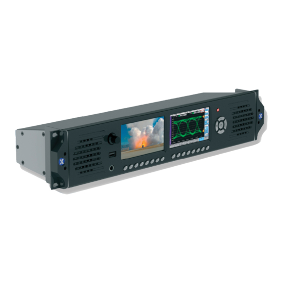
Rx2000 Description The Rx2000 is a 2U rack mounted instrument that provides the following: Two front panel TFT screens, one with a full range of generator, analyzer and system control menus, and selected analyzer instrument panels such as Waveform monitor, Vectorscope and Eye Pattern display;... -
Page 21: Rx Modules
Dual USB ports are provided for mouse and keyboard control. Ethernet provides remote access via web browser and is also the method for updating firmware and software from PHABRIX’s dedicated server. Bi/Tri level looping reference that allows the Rx instrument to be locked to a studio reference. -
Page 22: Single Analyzer, Dual Input
Single Analyzer, Dual Input The PHRXM-A module allows 2 connected OPTICAL SDI or Optical video signals to be present continuously and switched for analysis or display by the single analyzer channel as required. IN1 - LP1 SD-SDI or HD-SDI signal, high impedance loop through that allows the Rx instrument to analyse the connected input. -
Page 23: Aes Digital Audio Input / Output
2 signal is produced on the module’s “GEN B” output. Likewise if a Fibre connection is being used the Link 1 signal is produced on “OPTICAL GEN A” and the Link 2 signal is produced on “OPTICAL GEN B”. PHRX2000-201 8 Rx 2000 Operation Manual 1–7... -
Page 24: Rx Software Options
Rx Software Options Overview The Rx range has a range of software options that can enhance the Rx functionality for specific applications. 3G-SDI and advanced formats upgrade for Rx chassis This option (PHRXO-3G) provides advanced formats include 4:2:2 YUV, 4:4:4 RGB and 3G-A YCbCr-422-10 YCbCr-444-10... -
Page 25: Advanced Physical Layer Analysis
IP Sockets to allow any aspect of the unit to be modified or queried. This allows complex applications to be created to perform test and measurement functions such as automated testing of routers or other broadcast equipment. PHRX2000-201 8 Rx 2000 Operation Manual 1–9... -
Page 26: Dolby Metadata Generator
Messages may be sent to ‘set’ or ‘get’ data from a command ie if you ‘set’ a value the unit will be configured accordingly and a reply returned and if you ‘get’ a value from the PHABRIX unit it will reply with that value. All messages are acknowledged to increase the security of the interface ie closed loop communication. -
Page 27: Sdi-2K Formats
This option (PHRXO-4CAP) allows up to 4 channels of closed caption to be displayed. This is allocated as 1 channel per analyser module. This supports WTS/OP42/OP47, EIA 608 and EIA 708 closed caption / subtitle formats. PHRX2000-201 8 Rx 2000 Operation Manual 1–11... - Page 28 1–12 Description 07/17 PHRX2000-201 8...
- Page 29 ® PHABRIX® Front Panel broadcast excellence 2–1 PHRX2000-201 8 Rx 2000 Operation Manual...
- Page 30 2–2 Front Panel 07/17 PHRX2000-201 8...
-
Page 31: Front Panel Control
Front Panel Control Turning on and off the instrument To turn on your PHABRIX Rx2000 press the red button at the top right hand corner of the front panel. Volume Power Confidence Display Input/Preset Selection Buttons Menu Selection Buttons Navigation Buttons Once the system has started, pressing the button again will turn it off. -
Page 32: Confidence Display
Confidence Display The left-hand TFT screen is controlled by the 8 buttons beneath it that allow the inputs to all analyser modules to be selected. Top - (First Button) takes you to the top level of the simple menu. Input Bank 1 (Second Button) gives access to “SDI1a”, “FIB1a”, “SDI1b”, “FIB1b”, “SDI2a”, “FIB2a”, “SDI2b”, “FIB2b”. -
Page 33: Main Menu
OFF if the generator output is Off. The Jitter values will be shown in red if the jitter values are greater than the values specified on the Log Setup page for the relevant jitter meter. PHRX2000-201 8 Rx 2000 Operation Manual 2–5... -
Page 34: Using The Menus
Using the Menus The Menu buttons select which instrument is in use as well as selecting the options for the instrument. The bottom of the LCD display shows the function of each Menu button. When in a specific function eg Generator, Analyzer etc, the cursor controls () on the right hand of the instrument select a field to edit. -
Page 35: Multiple Analyzers
Link 2 signal must be connected to “IN2” BNC connector on the same Anayzer module. Likewise if Fibre is being used Link 1 should connect to “OPTICAL A” and Link 2 should connect to “OPTICAL B” PHRX2000-201 8 Rx 2000 Operation Manual 2–7... - Page 36 2–8 Front Panel 07/17 PHRX2000-201 8...
-
Page 37: Generator Menus
3G-level B in some formats. Which mode is selected determines which formats are available. Only valid frame rates for the output standard may be selected. PHRX2000-201 8 Rx 2000 Operation Manual 2–9... -
Page 38: Colour Format
Colour Format Currently only YCbCr 4:2:2 10 bit picture formats are supported by the standard product but an Option may be purchased to enable other colour formats. The following colour modes may be selected dependent on line standard selected: YCbCr 422 10bit YCbCr 444 12bit YCbCr 444 10bit YCbCrA 4444 10bit... - Page 39 The “Valid Ramp” test pattern is used to check the linearity of the Y (luminance), Cr (R-Y) and Cb (B-Y) components. This test pattern exercises all of the discrete digital video levels of these components, excluding illegal values. PHRX2000-201 8 Rx 2000 Operation Manual 2–11...
- Page 40 The “Grey Bar - 5” test pattern is used to check for non linear distortion in the luminance component. The bars range from 100% white to 0% black in 20% steps. Typically non linearity will be seen as a loss of grey-scale distinction.
- Page 41 XScale/Start Freq - sets the horizontal scale of grating patterns or the start value of the zone plate sweep frequency. YScale/End Freq - sets the vertical scale of grating patterns or the end value of the zone plate sweep frequency. PHRX2000-201 8 Rx 2000 Operation Manual 2–13...
-
Page 42: Edh
The Pathological test patterns are used to check that the phase locked loop circuitry used to decode SDI data can recover/regenerate the SDI sample clock under worst case conditions. EQ Test is a pathological signal that generates long run-lengths of 1s or 0s (for example 19 samples of 0 followed by a single 1) to test the accuracy of phase lock loop circuitry that recovers/the sample clock from the SDI data. - Page 43 The Caps Lock menu key locks the keyboard in all capitals mode. The Alt Gr. key shows any language dependent alternate keys that may be pressed. Several country keyboard styles are provided. Note that not all fonts support all non-English characters. PHRX2000-201 8 Rx 2000 Operation Manual 2–15...
-
Page 44: Frame Grab Playout
Frame Grab Playout Each Generator module within the system can play-out a video clip captured and saved using the Picture Frame Grab function. This can be used to playout generated test clips as well as video clips captured when an error condition occurred. The Frame Grab playout mode can be enabled by selecting Frame Grab from... -
Page 45: Genlock Menu
The Genlock menu is used to select an external locking reference or set the instrument to free run. Using the Rx 2000 front panel, the Genlock menu can be displayed by selecting the corresponding “Generator”... - Page 46 Free Run - where the Rx system uses its own internal locking reference. Ext. Ref - where the Rx system is locked to an analogue studio reference signal connected to the “Ref” input on the CPU module. SDI1 - where the Rx system is locked to the SDI input on a single input Analyser module fitted in module slot 1.
-
Page 47: Audio Group Menu
The Audio Group 1-4 and 5-8 menus control which audio channels, pairs or groups have test tones applied and the type of tone. Using the Rx 2000 front panel, the Audio Group 1/2 menu can be displayed by selecting the corresponding “Generator”... -
Page 48: Link
Link This links the left and right channels of a pair so that changing the level on the left hand channel changes the level on the right hand channel. Master The master level sets the 0dB level for all the embedded audio channels. Thus if the Master level is set to -18dB and group 1 pair 1 output is set to -2dB, the actual level output on that pair is -20dB. -
Page 49: Dolby (Dolby Metadata Generator Option)
(Programme 1) and optional ancillary programs. These 8 channels are compressed (loss-less) into a digital stream that can be transferred between compatible devices and stored on a standard stereo pair of audio tracks. PHRX2000-201 8 Rx 2000 Operation Manual 2–21... -
Page 50: Dolby Digital
Dolby Digital Dolby Digital (AC-3) is a ‘perceptual audio’ system for digital audio that allows the reduction of data needs to deliver high-quality sound. This system was developed primarily for DTV, DVD and HDTV. This format allow up to six channels of sound (mono, stereo or 5.1) in the form of a single ‘program’... -
Page 51: Editing Program Information
720p59 or 720p60 etc. The Dolby-E signal will always be generated at the related slower rate. This is a Dolby restriction as the packets are over 1 frame in length for these video formats. PHRX2000-201 8 Rx 2000 Operation Manual 2–23... -
Page 52: Program Meta Data Editing
Program Meta Data Editing Many of the metadata fields may be edited to test downstream equipment. The Channel Mode field may be edited to invalid settings but they will be shown in RED to show that they are invalid. The settings currently being edited are for the selected program but multiple program metadata values can be modified and the settings for all programs are stored in memories. -
Page 53: Default Program Meta Data
‘Dolby’ also. As the Dolby streams are data, the volume and phase controls are disabled. Changing a channel from Dolby to another source will cause the other channel in the pair to select silence. PHRX2000-201 8 Rx 2000 Operation Manual 2–25... -
Page 54: Embedding Dolby Signals On Aes Stream
Embedding Dolby Signals on AES Stream To embed Dolby signals on the AES output, the Audio source for the AES output should be set to “DolbyGen”. This selection is found on the right hand side of the Generator – Audio Group 1,2,3,4 pages. -
Page 55: Analyzer Menu
On the Rx 2000 front panel, the source for the analyzer is set by the field at the bottom right of the page. The current line and sample are the same for all pages of the analyzer and therefore when selecting a sample on the Signal Data page, the cursor will show where that is on the ‘Full Picture’... -
Page 56: Picture
Picture The Rx Instrument with an Analyzer Module installed can display the selected input in the form of a picture monitor. Using the Rx 2000 front panel, the Picture menu can be displayed by selecting the corresponding “Anayzer” button. The picture displayed is down-converted from the video source. The picture will automatically view the horizontal or vertical blanking areas if the line or sample values are in the blanking. -
Page 57: Sample, Line And Field Selection
2. The field number will change accordingly. Cursor & Zoom From the Rx 2000 front panel, if the focus cursor is moved to the picture window and OK pressed, the cursor may be used to scroll around the window. Press OK again to cancel this mode. -
Page 58: Frame Grab
Frame Grab Each Analyser module allows a video clip to be captured for analysis and playback. The video clip contains the full SDI data frame including video data, metadata and audio data. The video clip can be recorded manually or can be triggered by a number of different events such as EDH and CRC errors. - Page 59 Delete – allows the currently selected video clip in the drop down list to be deleted. The current progress of the Save or Load operation is display in the Progress thermometer. Note that video clips can be exported and imported using the USB copy menu PHRX2000-201 8 Rx 2000 Operation Manual 2–31...
-
Page 60: Signal Data
Signal Data The Rx Instrument with an Analyzer Module installed and SDI analysis option can display the selected input in the form of a data array. Using the Rx 2000 front panel, the Signal Data menu can be displayed by selecting the corresponding “Anayzer”... -
Page 61: Waveform Monitor
Waveform Monitor The Rx Instrument with an Analyzer Module installed can display the selected input in the form of a waveform monitor. Using the Rx 2000 front panel, the Waveform Monitor menu can be displayed by selecting the corresponding “Anayzer”... -
Page 62: All, Line And Sample
All, Line and Sample The display may be restricted to a single line or all lines may be displayed at the same time. The display can be formatted as all streams (Luma and Chroma) or just a single stream. The streams may be in YCbCr or GBR formats. The line, sample and field controls all track the related controls on other pages. -
Page 63: Vectorscope
Vectorscope The Rx Instrument with an Analyzer Module installed can display the selected input in the form of a vectorscope. Using the Rx 2000 front panel, the Vectorscope menu can be displayed by selecting the corresponding “Anayzer”... -
Page 64: Eye
The Rx Instrument with an Analyzer Eye Module installed can display the selected input in the form of an Eye Pattern. This allows the jitter of the selected input video signal to be monitored using an Eye Pattern display. Using the Rx 2000 front panel, the Eye menu can be displayed by selecting the corresponding “Anayzer”... -
Page 65: Eye Display
There is no method for the Rx instrument to view the signal post- equaliser. PHRX2000-201 8 Rx 2000 Operation Manual 2–37... -
Page 66: Jitter Filters
Jitter Filters The “Jitter 1” and “Jitter 2” filter options allow the specific type of jitter to be applied to the waveform and the thermometers displays. The options are: Timing as determined by the SMPTE standard for the specific video standard (ie jitter above the 10 Hz threshold) Align as determined by the SMPTE standard for the specific video standard (ie jitter... -
Page 67: Advanced Jitter Analysis (Option)
This button clears the eye display. It is only enabled when the update mode is set to infinite update mode. Eyes: Adjusts the number of eyes visible on the eye display. The 10 and 20 modes are useful for observing serial-parallel conversion jitter. PHRX2000-201 8 Rx 2000 Operation Manual 2–39... -
Page 68: Jitter
Jitter The Rx Instrument with an Analyzer Eye Module installed and Advanced Jitter Analysis option can display the selected input in the form of an Jitter waveform. Using the Rx2000 front panel, the Jitter menu can be displayed by selecting the corresponding “Anayzer”... -
Page 69: Signal Information Menus
Under normal conditions, the EDH-AP values should be constant, the full-field values may change if audio or other ancillary data is embedded in the SDI signal. PHRX2000-201 8 Rx 2000 Operation Manual 2–41... -
Page 70: Cable Length
The EDH flags for active picture, full-field and ancillary data are also displayed for diagnostic purposes. Edh: Error Detected Here - This is set to 1 if a SDI error was detected. In the case of ancillary data, this means that one or more ANC data packets had an incorrect checksum. -
Page 71: Misc Status
“Invalid” but the values in this section will be updated every few seconds. The Re-sync counter displays the number of times the SDI data has been re-synchronised and can help detect intermittent SDI signal problems. PHRX2000-201 8 Rx 2000 Operation Manual 2–43... -
Page 72: Video Timing
Video Timing The Rx Instrument with an Analyzer Module installed can monitor the selected input and display its timing relationship with the locking reference. Using the Rx 2000 front panel, the Video Timing menu can be displayed by selecting the corresponding “Sig Info”... -
Page 73: Anc Status (Sdi Analysis Option)
The Rx Instrument with an Analyzer Module installed and SDI analysis option can monitor the selected input and display details of any Ancillary packets within the SDI data stream. Using the Rx 2000 front panel, the ANC Status menu can be displayed by selecting the corresponding “Sig Info”... - Page 74 S305-SDTI this is the SMPTE 291M defined SDTI transport data packet in active frame space. S348-HDTI this is the SMPTE 291M defined HD-SDTI transport in active frame space. S427-Lnk. Enc 1 this is the SMPTE S427 defined link encryption data packet. S427-Lnk.
- Page 75 (ie to be ignored by down-stream processes. User-1 this is a user defined data packet. User-2 this is a user defined data packet. User-3 this is a user defined data packet. PHRX2000-201 8 Rx 2000 Operation Manual 2–47...
-
Page 76: Anc Inspector (Sdi Analysis Option)
ANC Inspector (SDI Analysis Option) The Rx Instrument with an Analyzer Module installed and SDI analysis option can monitor the selected input and display the contents of selected Ancillary packets within the SDI data. Using the Rx2000 front panel, the ANC Inspector menu can be displayed by selecting the corresponding “Sig Info”... -
Page 77: Anc Inspector Setup
The Setup dialogue also shows when an ANC packet has been detected and where it was found. This makes changing a filter simpler as the effect of the filter can be determined without closing the dialogue. This dialogue also allows the user defined ANC packets to be configured. PHRX2000-201 8 Rx 2000 Operation Manual 2–49... -
Page 78: Sfp Info
SFP Info The SFP Info menu displays details of the currently installed SFP module. Along with manufacturer’s details of the SFP’s parameters, this displays the transmitted and received power which can indicate optical losses in the infrastructure (optical fibre type, distance and connection quality) 2–50 Front Panel 07/17... -
Page 79: Audio Menus
Audio Meters The Rx Instrument with an Analyzer Module installed can monitor the selected input audio and graphically display the audio level for each audio channel. Using the Rx 2000 front panel, the Audio Meters menu can be displayed by selecting the corresponding “Audio”... -
Page 80: Audio Mix Mode
Setup The Mix Mode channel mappings can be saved as an audio preset using the “Save” button and recalled using the Rx 2000 front panel preset controls. 4AES Module The Rx Instrument with an 4AES Module installed can monitor the selected AES input audio pairs and graphically display the audio level for up to 4 pairs of AES audio channels. -
Page 81: Audio Status
Audio Status The Rx Instrument with an Analyzer Module installed can monitor the selected input audio and detail its audio encoding details. Using the Rx 2000 front panel, the Audio Status menu can be displayed by selecting the corresponding “Audio” button. -
Page 82: Dolby Status (Dolby Analyzer Option)
Dolby Status (Dolby Analyzer Option) The Rx Instrument with an Analyzer Module installed and Dolby Analyzer Option can monitor the selected input audio and provide details of its Dolby E audio encoding. Using the Rx2000 front panel, the Dolby menu can be displayed by selecting the corresponding “Audio”... -
Page 83: Dolby Digital Plus
It is important for the Dolby E packet to be positioned well away from the video switching line so that Dolby E packets are not corrupted by downstream switchers. At all places in the signal PHRX2000-201 8 Rx 2000 Operation Manual 2–55... -
Page 84: Dolby E Programme Configuration
chain where audio can be delayed by a different value to the video, the Dolby E packet needs to be re-timed to make sure that this timing specification is met. The position of the Dolby E packet in the video frame is displayed in lines and micro-seconds (us). Dolby E Timing source Dolby E timing may be measured relative to the SDI input or the External reference. -
Page 85: Programme Metadata
Dolby Surround Ex channel that provides an extra audio channel for Dolby 5.1. The extra surround channel of the Dolby Surround Ex system is matrix-encoded onto the discrete left-surround and right- surround channels of the 5.1 mix. PHRX2000-201 8 Rx 2000 Operation Manual 2–57... -
Page 86: Peak Metering
The following control bits can also be viewed: the LFE Channel parameter enables or disables the Low-Frequency Effects (LFE) channel. this parameter can be used to activate the DC High pass filter for all input channels. the LFE Low pass Filter parameter can be used to activate a 120 Hz low- pass filter applied to the LFE input channel. -
Page 87: Loudness Meters
“Save Name” text box will bring-up an on-screen keyboard to allow the CSV file to be named appropriately. These logs can be copied onto a USB pen drive if it inserted in to the front panel and selected using from the loudness folder. PHRX2000-201 8 Rx 2000 Operation Manual 2–59... -
Page 88: Mode
Mode The loudness is measured simultaneously with three different time periods: M (momentary) covering the shortest timescale of 400ms S (short term) covering the intermediate timescale of 3 seconds I (integrated) covering the duration of a program or segment The M, S and I values are displayed for the selected audio pair or 5.1 surround sound audio channels. -
Page 89: Confidence Check
Dolby channels, pairs of channels or a mixed- down version can be selected. Note that the Dolby Decoder settings are stored as part of the system configuration and cannot be saved in presets. PHRX2000-201 8 Rx 2000 Operation Manual 2–61... - Page 90 2–62 Front Panel 07/17 PHRX2000-201 8...
-
Page 91: System Menus
Move the cursor to the ‘Recall’ button and press ‘OK’ . The text field under the Memory list will change to show the last Saved or Recalled memory. PHRX2000-201 8 Rx 2000 Operation Manual 2–63... -
Page 92: Renaming Preset
Renaming Preset Select the Preset to be renamed by moving the cursor to the ‘Select Memory’ list and pressing ‘OK’ . Use the up/down cursor keys to select the memory and then press ‘OK’ . The name edit field next to the memory list will be updated with the name of the selected memory. Move the cursor to the edit field and press ‘OK’... -
Page 93: Network
On all Rx instruments the network addressing can be setup using the HDMI® monitor output. On the Rx 2000 instrument the IP Address can be setup using the Front Panel menus. Note that if the Rx instrument is turned on without the network connected, you will have to select the “Re-connect”... -
Page 94: Remote Control Of Rx Instrument
The Rx instrument uses a default Port Number of 2100 for remote control access (See Remote Control SDK documentation on Download section of PHABRIX Web Site) This port number may now be changed if it conflicts with other applications in your system. -
Page 95: Info
Un-check the “Change” check box to action the Date and Time change. Setting LCD Brightness Use the LCD brightness slider to set the front panel screen brightness. PHRX2000-201 8 Rx 2000 Operation Manual 2–67... -
Page 96: Setting User Language
Setting User Language The language used to display the menus in may be changed to one of the supported languages. (Currently only English is supported) Changing Options Security Code When new options are purchased for the Rx instrument a new Security Code will be supplied. This is specific to this instrument and cannot be used on other units. -
Page 97: Utils
The current status of the hardware modules can be viewed using the Utils menu. This menu displays details of the Rx instrument’s module (board) operating status and details the system temperature and individual board voltages. Using the Rx 2000 front panel, the Utils menu can be displayed by selecting the corresponding “System”... -
Page 98: Hardware Status
Hardware Status This section of the menu shows any hardware errors that have been recorded by the Rx instrument. If the error count is greater than 0, contact you local dealer for advice. System Temperature This section of the menu displays the current Rx instrument temperature. This information is provided for diagnostics purposes only. -
Page 99: Engineer
Pressing the Download button will cause the current release of software to be downloaded from the Phabrix Web Site. This will take a short time dependent on the connection to the Internet. Once the download has completed, the software will be checked for errors before being stored on the Rx instrument for future installation. - Page 100 2. To install the downloaded software on the Rx instrument, select the release using the field with releases listed. The largest number is the latest release. Select the ‘Install’ button and a confirmation dialogue will be shown. Press “Yes” and the installation will start.
-
Page 101: Hdmi/Sdi Output
With the HDMI output enabled (always enabled on the Rx 500 and Rx 1000 instruments and configurable on the Rx 2000 instrument) then the frame rate of the SDI output is limited to be match to the HDMI output. The HDMI standard and frame rate combo-boxes will be limited to 1080p 50/59/60. -
Page 102: Using Sdi Output As Test Pattern Generator
Using SDI output as Test Pattern Generator The SDI output on the CPU module can be used as a test pattern and audio tone generator. This output is limited to specific test patterns and can only provide audio tones for Audio Group 1 Select the required video format, line rate and frame rate from the drop down menus in the “CPU SDI Output”... -
Page 103: Speaker Menu
Speaker / Headphone The Rx 2000 instrument contains stereo loud speakers and associated stereo headphone socket which can be connected to any of the audio input or output channels or pairs. The “Mute” check box allows both signals to be muted. - Page 104 2–76 Front Panel 07/17 PHRX2000-201 8...
-
Page 105: Logging Menus
“Logging” button. Pressing the OK button on the Rx 2000 front panel when the highlight is on the event log page allows the event log to be scrolled through to view all events in the list. The currently selected event is shown on the event log header. -
Page 106: Log Setup
Log Setup The Log Setup menu allows specific events to be tracked by the Rx instrument. The events to be logged are set up on this page by checking the appropriate ‘Log’ check boxes. Using the Rx2000 front panel, the Log Setup menu can be displayed by selecting the corresponding “Logging”... -
Page 107: Aes Status
Event Log if they happen. If you are having problems with your Rx instrument, checking this box can add events that can help PHABRIX determine the nature of the problem. Save saves the current event log to a text file in the currently specified language. -
Page 108: Log Eye Jitter
The Eye Log Setup menu allows specific Eye and Jitter events to be tracked by the Rx instrument. The events to be logged are set up on this page by checking the appropriate ‘Log’ check boxes. Using the Rx 2000 front panel, the Log Eye Jitter menu can be displayed by selecting the corresponding “Logging”... -
Page 109: Log Anc Status
The Log ANC Status menu allows specific ANC data events to be tracked by the Rx instrument. The events to be logged are set up on this page by checking the appropriate ‘Log’ check boxes. Using the Rx 2000 front panel, the Log ANC Status... - Page 110 2–82 Front Panel 07/17 PHRX2000-201 8...
-
Page 111: Admin Menus
Copy -> copies the currently selected/highlighted file in the USB route directory to the currently selected Rx folder. <-Copy copies the currently selected/highlighted file in the selected Rx folder to the USB route directory. PHRX2000-201 8 Rx 2000 Operation Manual 2–83... - Page 112 Before the USB pen drive is removed from the Rx unit, select the Eject button to close the session. This will prevent accidental damage or corruption of the files on the USB pen drive. 2–84 Front Panel 07/17 PHRX2000-201 8...
- Page 113 PHRX2000-201 8 Rx 2000 Operation Manual 2–85...
- Page 114 ® PHABRIX® Monitor Output broadcast excellence 3–1 PHRX2000-201 8 Rx 2000 Operation Manual...
- Page 115 3–2 Monitor Output 07/17 PHRX2000-201 8...
-
Page 116: Overview
Note that on the Rx 500 and Rx 1000 instruments, the Monitor Output is always enabled. But on the Rx 2000 instrument, however, the Monitor output can be enable/disabled in the “HDMI/ SDI Output” menu that is available from the Instrument Display on the front of the instrument. -
Page 117: Locking Reference Vitc And Ltc
Locking Reference VITC and LTC Vertical Interval Timecode (VITC) and Longitudinal Timecode (LTC) present on the analogue (625i/50 and 525i/59.94) locking reference signal connected to the “REF” connection on the rear of the Rx unit can be displayed on the Task Bar of the HDMI® monitor output. The locking reference can be selected by pressing the “Ref”... -
Page 118: Managing The Monitor Output
Link 2 signal must be connected to “IN2” BNC connector on the same Anayzer module. Likewise if Fibre is being used Link 1 should connect to “OPTICAL A” and Link 2 should connect to “OPTICAL B” PHRX2000-201 8 Rx 2000 Operation Manual 3–5... -
Page 119: Working With Multiple Generators
Working with Multiple Generators When the Rx instrument contains multiple Generator modules, the generator to be controlled can be selected from the drop-down list in the corner of the panel (GEN1, GEN2, etc). Note that the PHRXM-GG module has 2 outputs (GEN-A and GEN-B) but this is treated as a single Generator as the outputs are locked together. -
Page 120: Generator Panels
Clicking on instrument type title (Generator, Generator Audio 1-4, Generator Audio 5-8, Generator Reference) allows the generator type to be changed. Generator Audio 1-4 Generator 1 Generator Audio 5-8 Generator 2 Generator Reference PHRX2000-201 8 Rx 2000 Operation Manual 3–7... -
Page 121: Generator Video
Generator Video The Rx instrument with a Generator Module installed can create video test signals for all supported SD and HD SDI output standards including the 3GHz standards at 1080p/50/59/60. It will support Y,Cr,Cb formats as well as RGB formats. The Generator Video window is accessed by clicking on a Generator slot on the... -
Page 122: Pattern
SMPTE colour bars (developed by the Japanese Association of Radio Industry and Businesses) and standardized as SMPTE RP 219-2002 and is used to test both 4×3 standard definition and 16×9 high-definition video signals. PHRX2000-201 8 Rx 2000 Operation Manual 3–9... - Page 123 The AV Delay Test pattern and audio tone provided by the Generator module can be used to check any delay between the video and audio. This animated test pattern provides a constantly moving Clapper board and corresponding AV Delay tone when the clapper board reaches the centre of the test pattern.
- Page 124 The ‘->’ button displays a dialogue which allow the parameters of the zone plate to be adjusted for the custom zone plates. Any of the preset zone plates may be PHRX2000-201 8 Rx 2000 Operation Manual 3–11...
- Page 125 copied to the custom zone plates to act as a starting point for a new zone plate. As the zone plate settings are stored in user memories a large number of custom zone plates are available: Moving Zone-2H - A moving zone plate centred on the screen. Static Zone-2H - A static zone plate centred on the screen from DC to the nyquist frequency at left/right edges.
-
Page 126: Edh
Left-Centre, Centre-Screen, Right Centre, Bottom-Left, Bottom-Centre, Bottom-Right. When text ident is used, the font, font size and colour can be specified. Several fonts are built in to the Rx instrument, other true-type (.ttf) fonts may be downloaded as required. PHRX2000-201 8 Rx 2000 Operation Manual 3–13... -
Page 127: Frame Grab Playout
When editing text, the keyboard above is displayed to allow easy editing. Move the cursor to select the key to ‘press’ and then press ‘Ok’ to ‘press’ it. The Shift menu key causes the next keyboard to change to shift mode for the next key press. -
Page 128: Generator Reference
Bi-Level/Tri-Level sync or may be locked to the video input. Alternatively, the generator may free run. Delay The test patterns generated by the Generator module can be delayed or advanced with respect to the locking reference input using the Lines and Pixel values. PHRX2000-201 8 Rx 2000 Operation Manual 3–15... -
Page 129: Generator Output Audio Menu
Generator Output Audio Menu The Rx instrument with a Generator Module installed can embed an audio signal on all 16 embedded audio outputs. The Output Audio 1 and 2 menus control which audio channels, pairs or groups have test tones applied and the type of tone. The Output Audio 1 window is accessed by clicking on a Generator slot on the... -
Page 130: Link
If DolbyGen is selected as the Source for any AES output, the Dolby Generator in the System menu needs to be set to External reference otherwise the Dolby audio packet may not be embedded into the AES stream in the correct place. PHRX2000-201 8 Rx 2000 Operation Manual 3–17... - Page 131 3–18 Monitor Output 07/17 PHRX2000-201 8...
-
Page 132: Analyzer Panels
The 4AES module provides audio-only analysis tools and audio-only generation tools. Pressing the left-hand AES button (input) will display the analyser functions that are available and pressing on the right-hand AES button (output) will display the Output audio configuration menu. PHRX2000-201 8 Rx 2000 Operation Manual 3–19... -
Page 133: Picture
Picture The Rx Instrument with an Analyzer Module installed can display the selected input in the form of a picture monitor. The Picture window is accessed by clicking on an Analyzer slot on the monitor output task bar and selecting “Picture”. -
Page 134: Safe Area Generator
If the Cursor is used then the expanded image will be placed about the selected cursor position. Clicking and dragging on the image will move the zoomed image. PHRX2000-201 8 Rx 2000 Operation Manual 3–21... -
Page 135: Closed Caption / Subtitle Display
Closed Caption / Subtitle Display If the closed caption option is installed, the Caption Options menu allows the selection of WST/ OP42/OP47, EIA 608 and EIA 706 subtitles. Closed caption text will be displayed in the image area as defined by the closed caption formatting information relevant to the closed caption type. -
Page 136: Gamut Error Indication
Both AFD/WSS and V-Chip monitoring is displayed in the top right corner of the image to allow quality control of programme material to be performed prior and during transmission. These can be enabled by using the Picture contextual menu (mouse right click in image area). PHRX2000-201 8 Rx 2000 Operation Manual 3–23... -
Page 137: Frame Grab
Frame Grab Each Analyser module allows a video clip to be captured for analysis and playback. The video clip contains the full SDI data frame including video data, metadata and audio data. The video clip can be recorded manually or can be triggered by a number of different events such as EDH and CRC errors. - Page 138 Delete – allows the currently selected video clip in the drop down list to be deleted. The current progress of the Save or Load operation is display in the Progress thermometer. Note that video clips can be exported and imported using the USB copy menu. PHRX2000-201 8 Rx 2000 Operation Manual 3–25...
-
Page 139: Data View / Signal Data
Data View / Signal Data The Rx Instrument with an Analyzer Module installed and SDI analysis option can display the selected input in the form of a data array. The SDI Data window is accessed by clicking on an Analyzer slot on the monitor output task bar and selecting “Data View”. -
Page 140: Waveform Monitor
The vertical scale (x1 V) of the waveform (at 16th window size on the HDMI output) can be selected to view the high, middle and low areas of the waveform display. PHRX2000-201 8 Rx 2000 Operation Manual 3–27... -
Page 141: Cursors
Cursors Cursors are available on the Waveform monitor to measure amplitude and timing: Pict: The Picture cursor displays the currently selected cursor on the Picture window. If all is turned off this will automatically select the line and sample on the Waveform monitor. Time The Time cursors allow the difference between to points (Cursor A and Cursor B) to be measured. -
Page 142: All, Line And Sample
The axes and measurements for the waveform monitor can be displayed either in percentages or in hex or decimal values as required. Horizontal Scale: The timing measurements may be set in either pixels or micro-seconds (us) PHRX2000-201 8 Rx 2000 Operation Manual 3–29... -
Page 143: Vectorscope
Vectorscope The Rx Instrument with an Analyzer Module installed can display the selected input in the form of a vectorscope. The Vectorscope window is accessed by clicking on an Analyzer slot on the monitor output task bar and selecting “Waveform”. This will create a new window panel for the selected input. -
Page 144: Eye
Electromagnetic interference in Long cable lengths that may be susceptible to interference from the power grid and from power switching. Distorted waveform shape, created by equipment, by long cable runs, by poorly terminated, un-equalised cables, poor cable frequency response of or poor return-loss. PHRX2000-201 8 Rx 2000 Operation Manual 3–31... -
Page 145: Eye Display
Problems occur when these errors cause a level of jitter outside the specified acceptable parameters. The different types of jitter are classified as follows: Timing Jitter refers to a short-term time interval error above a low frequency threshold of 10 Hz (as defined in the SMPTE standards for SDI signals). Alignment Jitter refers to artefacts above the specified threshold frequencies of (1 kHz for SD-SDI signals and 100 kHz for HD-SDI signals). -
Page 146: Jitter Filters
The eye colour may be set to green or blue and may also be adjusted in gain to allow the eye display to show ‘hot spots’ where the majority of the signal data is found. PHRX2000-201 8 Rx 2000 Operation Manual 3–33... -
Page 147: Advanced Jitter Analysis (Option)
Advanced Jitter Analysis (Option) The Advanced Jitter Analysis option provides the user with additional tools on the Eye display to help determine the nature of jitter present in SDI signals. Histogram: Amp/Timing/Both. Histograms enable the operator to observe the distribution of samples in both amplitude (Amp) and time (Time). -
Page 148: Jitter
It is only enabled when the update mode is set to infinite update mode. Clear: This button clears the eye display. It is only enabled when the update mode is set to infinite update mode. PHRX2000-201 8 Rx 2000 Operation Manual 3–35... -
Page 149: Video Status
Video Status The Rx Instrument with an Analyzer Module installed can monitor the selected input and display any EDH (error detection and handling) or CRC (cyclic redundancy check) errors detected in the data stream. The Video Status window is accessed by clicking on an Analyzer slot on the monitor output task bar and selecting “SDI Errors”. -
Page 150: Cable Length
CRCs are calculated for each of the packed 10-bit virtual interfaces and will therefore generate different values from those for YCC422-10. See the “Active Picture CRC Technical Information” section at the end of the manual for details of CRC calculation. PHRX2000-201 8 Rx 2000 Operation Manual 3–37... -
Page 151: Misc Status
Misc Status The Rx Instrument with an Analyzer Module installed can monitor the selected input and display the content of any SMPTE 352 packets detected in the data stream. The Misc Status window is accessed by clicking on an Analyzer slot on the monitor output task bar and selecting “Input Status”. -
Page 152: Video Timing
1 on the reference signal. This can lead to different values to other test and measurement instruments that include an SD (PAL/NTSC) offset in their calculations. By comparing line 1 timings, the Rx instrument can be used to accurately measure time delays through up/down/cross converters. PHRX2000-201 8 Rx 2000 Operation Manual 3–39... -
Page 153: Anc Status (Sdi Analysis Option)
ANC Status (SDI Analysis Option) The Rx Instrument with an Analyzer Module installed and SDI analysis option can monitor the selected input and display details of any Ancillary packets within the SDI data stream. The Ancillary Packet Status window is accessed by clicking on an Analyzer slot on the monitor output task bar and selecting “ANC... - Page 154 ARIB defined user data 1 packet in the VANC space. ARIB-B.23-2 this is the ARIB defined user data 2 packet in the VANC space. ARIB-B.27 Capt. this is the ARIB defined caption data in the VANC space. PHRX2000-201 8 Rx 2000 Operation Manual 3–41...
- Page 155 ARIB-B.35 this is the ARIB defined trigger signal data packet for data broadcasting. ARIB-B.39 this is the ARIB defined inter-stationary control data packet in the VANC space. ARIB-B.37 this is the ARIB defined analogue signal data in the VANC space. ARIB-B.37 HD this is the ARIB defined HD data packet in the VANC space.
-
Page 156: Anc Inspector (Sdi Analysis Option)
Inspector setup dialogue below. Un-checking the freeze button will restore normal operation. The “->Cursor” button will copy the Line and Sample numbers to the SDI data view cursors to simplify navigation to the ANC packet under investigation. PHRX2000-201 8 Rx 2000 Operation Manual 3–43... -
Page 157: Anc Inspector Setup
ANC Inspector Setup If the Setup button is pressed a dialogue box is shown to allow the ANC packet trigger parameters to be set. The trigger parameters allow only selected lines to be checked or excluded when checking for the presence of packets. Line Range Filer If either of the Line Range Filter check boxes are checked then the range of lines that the ANC inspector will check is limited to that range. -
Page 158: Sfp Information
SFP module. Along with the manufacturer’s details of the SFP’s parameters, this displays the transmitted and received power which can indicate optical losses in the infrastructure (optical fibre type, distance and connection quality) PHRX2000-201 8 Rx 2000 Operation Manual 3–45... -
Page 159: Audio Meters
Audio Meters The Rx Instrument with an Analyzer Module installed can monitor the selected input audio and graphically display the audio level for each audio channel. The Audio Metering window is accessed by clicking on an Analyzer slot on the monitor output task bar and selecting “Audio Meters”. -
Page 160: Meter Setup
System - Surround Channel Setup The Mix Mode channel mappings can be saved as an audio preset using the “Save” button and recalled using the front panel preset controls. PHRX2000-201 8 Rx 2000 Operation Manual 3–47... -
Page 161: 4Aes Module
4AES Module The Rx Instrument with an 4AES Module installed can monitor the selected AES input audio pairs and graphically display the audio level for up to 4 pairs of AES audio channels. Dolby Metadata Analysis If the metadata Dolby analyzer option is installed, selecting Metadata from the drop down list on the meter window will display the encoded Dolby metadata levels for up to 8 Dolby channels within the specified embedded audio pair or AES input. -
Page 162: Sdi Audio Status
The stereo audio pair to be monitored can be selected from the drop down list. If a Dolby Decoder module is installed then a mixed-down version of the decoded Dolby digital audio channels can be displayed. PHRX2000-201 8 Rx 2000 Operation Manual 3–49... -
Page 163: Loudness Meters
Loudness Meters The tools provided in the “Loudness” window allow the loudness of the selected source stereo audio pair, 5.1 surround sound audio group or decoded Dolby program (from the Dolby Decoder module) to be monitored and measured. The Rx system provides a single Loudness meter as standard and an additional 3 Loudness meters are available as an option and allocated as 1 loudness channel per analyser module. -
Page 164: Mode
The Audio and dBFS drop downs in the Scales section allows the scales of the audio channel meters to be selected. The actual scale of the Loudness meter is defined by the loudness mode selection. PHRX2000-201 8 Rx 2000 Operation Manual 3–51... -
Page 165: Confidence Check
The “Integrated” (Infinity), “Momentary” and “Short Term” target values define the level, above which, a loudness error is logged as exceeding the defined upper limits. The errors count is displayed on the Loudness window. If Targets - Enable is selected in the “Local Options” section, cursors will be displayed on the meter bar and the loudness values will flash red when the target level is exceed. -
Page 166: Dolby Meta-Data (Dolby Analyzer Option)
‘program’ that can be delivered at different bit rates. These 6 channels are compressed (lossy) into a digital stream that can be broadcast. The most elaborate mode in common use is Dolby 5.1 with uses all six channels to provide surround sound. PHRX2000-201 8 Rx 2000 Operation Manual 3–53... -
Page 167: Dolby Digital Plus
Dolby Digital Plus Dolby Digital Plus (E-AC-3) is a more advanced version of Dolby Digital that provides a more efficient encoding algorithm that provide enough bandwidth that allows up to 20 channels of audio (mono, stereo, 5.1, 7.1 up to 13.1) that for a primary programme (Programme 1) and optional ancillary programs that can be delivered at much lower bit rates than Dolby Digital. -
Page 168: Dolby E Programme Configuration
Program selection: Selects which set of program meta-data is shown. Up to 8 programs can be encoded in the Dolby E packet dependent on the Program Configuration. User defined description for the selected program. Program description: PHRX2000-201 8 Rx 2000 Operation Manual 3–55... -
Page 169: Dolby Digital Programme Configuration
Dolby Digital Programme configuration When Dolby Digital metadata is analysed this displays channel configuration and limited metadata that is sent with Dolby Digital. Dolby Digital Plus Programme configuration When Dolby Digital Plus metadata is analysed this displays the Main, Dependent and Independent program stream configuration and limited metadata that is... - Page 170 0, it is not copyright protected. RF 0v Prot the RF Over-modulation Protection parameter determines whether or not an RF pre-emphasis filter is used in the overload protection algorithm to prevent RF over-modulation in set-top box decoders. PHRX2000-201 8 Rx 2000 Operation Manual 3–57...
-
Page 171: Peak Metering
Peak Metering The peak audio levels are included in the Dolby E metadata packet and may be displayed on the Audio - Meters page. Select the appropriate set of meters to display Dolby levels and then they will follow the selected Dolby E source. Note that audio cannot be decoded by the Rx range of products and so you will NOT be able to listen to the Dolby E signal. -
Page 172: System Panels
System Panels Overview Clicking on the System menu will allow the following window panels to be displayed. PHRX2000-201 8 Rx 2000 Operation Manual 3–59... -
Page 173: Network
Network The Rx Instrument is fully network compatible and has a complete network interface to allow control of any Rx instrument from any other unit. The Network menu allows the Rx instrument to be configured as part of a network The Network Setup window is accessed by clicking on the System menu on the monitor... -
Page 174: Remote Control Of Rx Instrument
The Rx instrument uses a default Port Number of 2100 for remote control access (See Remote Control SDK documentation on Download section of PHABRIX Web Site) This port number may now be changed if it conflicts with other applications in your system. -
Page 175: Engineer
Pressing the Download button will cause the current release of software to be downloaded from the Phabrix Web Site. This will take a short time dependent on the connection to the Internet. Once the download has completed, the software will be checked for errors before being stored on the Rx instrument for future installation. - Page 176 They can be restored from the System-Memories page using the Restore button and selecting the ‘_Before_Upgrade’ archive. The software release notes can be viewed by selecting the Changes button. PHRX2000-201 8 Rx 2000 Operation Manual 3–63...
-
Page 177: Hdmi/Cpu Sdi Setup / Hdmi/Sdi Output
With the HDMI output enabled (always enabled on the Rx 500 and Rx 1000 instruments and configurable on the Rx 2000 instrument) then the frame rate of the SDI output is limited to be match to the HDMI output. The HDMI standard and frame rate combo-boxes will be limited to 1080p 50/59/60. -
Page 178: Using Sdi Output As Test Pattern Generator
(for example a 625/50 locking reference and a 23.98 generated test pattern) then there will be a static lock between them but this will not be consistent. PHRX2000-201 8 Rx 2000 Operation Manual 3–65... -
Page 179: System Info
Pressing the Download button will cause the current release of software to be downloaded from the Phabrix Web Site. This will take a short time dependent on the connection to the Internet. Once the download has completed, the software will be checked for errors before being stored on the Rx instrument for future installation. - Page 180 They can be restored from the System-Memories page using the Restore button and selecting the ‘_Before_Upgrade’ archive. The software release notes can be viewed by selecting the Changes button PHRX2000-201 8 Rx 2000 Operation Manual 3–67...
-
Page 181: Board Status
Board Status The Board Status window displays the current status of the hardware modules on the HDMI® monitor output. This can then be used to inspect which Modules have been installed in the Rx instrument. The Board Status window is accessed by clicking on the System menu on the monitor output task bar and selecting “Board Status”. -
Page 182: Date/Time Setup
The system will check every 24 hours to ensure that the system time is synchronised. Un-check the “Change” check box to action the Date and Time change. PHRX2000-201 8 Rx 2000 Operation Manual 3–69... -
Page 183: Audio Monitoring Setup
Monitor Setup”. Speaker / Headphone The Rx 2000 instrument contains stereo loud speakers and associated stereo headphone socket which can be connected to any of the audio input or output channels or pairs. The Rx 1000 and Rx 500 instruments only have a stereo headphone socket. -
Page 184: Dolby Decoder Setup
Dolby channels, pairs of channels or a mixed- down version can be selected. Note that the Dolby Decoder settings are stored as part of the system configuration and cannot be saved in presets. PHRX2000-201 8 Rx 2000 Operation Manual 3–71... -
Page 185: Surround Channel Setup
Surround Channel Setup Throughout the Rx instrument wherever 5.1 surround sound audio is used the actual physical audio channel mapping that is used is defined in the Surround Channel Setup menu. The Surround Channel Setup window is accessed by clicking on the System menu on the monitor output task bar and selecting “Surround Channel Setup”. -
Page 186: Default Window Size
(1/16 screen size) or Quad (1/4 screen size). The default size of the Picture and Waveform windows can also be set to Large (3/4 screen size) or Full (full screen native video format display). PHRX2000-201 8 Rx 2000 Operation Manual 3–73... -
Page 187: Dolby Generator Setup (Dolby Generator Option)
Dolby Generator Setup (Dolby Generator Option) The Dolby Metadata Generator software option allows generation of Dolby-E, Dolby Digital and Dolby Digital Plus pre-encoded test signals to check that they are transferred transparently through the broadcast chain unaffected by routers/switchers, satellite links, etc. -
Page 188: Dolby Digital
1 frame long Note that for high frame rate progressive video formats being generated the Rx chassis MUST HAVE a compatible frame rate locking reference and the Dolby Generator MUST BE set to External Reference. PHRX2000-201 8 Rx 2000 Operation Manual 3–75... -
Page 189: Editing Program Information
Editing Program Information Stream type: Dolby-E, Dolby Digital and Dolby Digital Plus streams can be generated. Config, Bit Depth: The program configuration and Bit Depth can be changed to load the pre- encoded file. Stream contents: The tones generated are of a fixed predefined frequency. Four sets of pre- encoded streams are provided: Ramp Var - Each channel has a different frequency to allow checking of channels. - Page 190 DownMixMod this controls the Down Mix Mode which is used by the content creator to optimize Center and Surround channel levels for use in stereo down mix mode for any two-channel programmes. PHRX2000-201 8 Rx 2000 Operation Manual 3–77...
-
Page 191: Default Program Meta Data
D Sur Ex this controls the Dolby Surround Ex channel that provides an extra audio channel for Dolby 5.1. The extra surround channel of the Dolby Surround Ex system is matrix-encoded onto the discrete left-surround and right-surround channels of the 5.1 mix. The following control bits can also be set: the LFE Channel parameter enables or disables the Low-Frequency Effects (LFE) channel. -
Page 192: Logging Panels
Note that the event log only shows changes in status, so if the input is always in error and never good, an event will not be shown. To get the full state of the instrument will require looking at the current status as well as the event log. PHRX2000-201 8 Rx 2000 Operation Manual 3–79... -
Page 193: Log Setup
Log Setup The Log Setup menu allows specific events to be tracked by the Rx instrument. The events to be logged are set up on this page by checking the appropriate ‘Log’ check boxes. The Log Setup window is accessed by clicking on the Logging menu on the monitor output task bar and selecting “Log Setup”. -
Page 194: Aes Status
Event Log if they happen. If you are having problems with your Rx instrument, checking this box can add events that can help PHABRIX determine the nature of the problem. Save saves the current event log to a text file in the currently specified language. -
Page 195: Eye Log Setup / Log Eye Jitter
Eye Log Setup / Log Eye Jitter The Eye Log Setup menu allows specific Eye and Jitter events to be tracked by the Rx instrument. The events to be logged are set up on this page by checking the appropriate ‘Log’ check boxes. -
Page 196: Log Anc Status
This allows the user to define and name their own DID/SDID values for an ANC packet type. Reset Clears the state for all packet types and thus a packet that was displayed as previously in error is shown as OK. PHRX2000-201 8 Rx 2000 Operation Manual 3–83... - Page 197 3–84 Monitor Output 07/17 PHRX2000-201 8...
-
Page 198: Preset Memories
This also covers any Dolby metadata settings. ANC - not currently used. Ref - if this check box is selected then the Generator Genlock settings for all Generator modules will be saved as part of the preset. PHRX2000-201 8 Rx 2000 Operation Manual 3–85... -
Page 199: Analyser Section
Analyser Section The Analyser section controls the settings of all Analyser modules installed in the system: Video - if this check box is selected then the configuration of the Picture, Waveform, Vectorscope and Video Timing instruments for all modules will be saved as part of the preset. -
Page 200: Recalling Presets
Move the cursor to the ‘Clear’ button and press ‘OK’ . The memory list will show the default name for that memory. A cleared memory cannot be recalled. PHRX2000-201 8 Rx 2000 Operation Manual 3–87... -
Page 201: Exporting Presets
Exporting Presets Presets can be exported to a single file for backup purposes and re-imported into the internal format. This allows different sets of memories to be used for different tasks, such as command scripts. Exported memories are in a text format and so may be edited on a PC and downloaded to/from the backups directory on the Rx instrument via FTP or USB. -
Page 202: System Reference
System Reference should be set to external reference unless one is not available in which case the System Reference should be set to the specific SDI input where the Dolby digital audio is embedded. PHRX2000-201 8 Rx 2000 Operation Manual 3–89... - Page 203 In situations where there is no studio reference or when the SDI input is asynchronous and when decoding Dolby audio or routing embedded SDI audio channels to the AES output (4AES module) then the System Reference should be set to the SDI input containing the Dolby audio or embedded audio channels.
-
Page 204: Admin Menus
Copy -> copies the currently selected/highlighted file in the USB route directory to the currently selected Rx folder. <-Copy copies the currently selected/highlighted file in the selected Rx folder to the USB route directory. PHRX2000-201 8 Rx 2000 Operation Manual 3–91... - Page 205 Before the USB pen drive is removed from the Rx unit, select the Eject button to close the session. This will prevent accidental damage or corruption of the files on the USB pen drive. 3–92 Monitor Output 07/17 PHRX2000-201 8...
- Page 206 PHRX2000-201 8 Rx 2000 Operation Manual 3–93...
-
Page 207: Browser Control
® Browser Control PHABRIX® broadcast excellence 4–1 PHRX2000-201 8 Rx 2000 Operation Manual... - Page 208 4–2 Browser Control 07/17 PHRX2000-201 8...
-
Page 209: Overview
Analyzer allows the selected input signal to be analysed in the form of a Picture, Waveform monitor, Vectorscope and Eye Pattern display (option). PHRX2000-201 8 Rx 2000 Operation Manual 4–3... -
Page 210: Log Link
Sig Info allows detailed signal information about the video and audio status for the analyzer source to be displayed. Audio gives access to the Audio Meters and Audio Status displays. System allows the setup of system wide settings including memories, date/time and software. - Page 211 ® PHABRIX® Glossary broadcast excellence A–1 PHRX2000-201 8 Rx 2000 Operation Manual...
-
Page 212: Glossary
A–2 Glossary 07/17 PHRX2000-201 8... -
Page 213: Glossary Of Terms
¼ inch head phone socket used for local audio monitoring. Bar Data defines the extent of the image within the coded frame as part of the AFD (active format description as defined by SMPTE S2016. PHRX2000-201 8 Rx 2000 Operation Manual A–3... - Page 214 Chassis is the physical enclosure of the Rx range that is used to mount various hardware modules. Central Processor Unit (cyclic redundancy check) is an error-detecting code commonly used in digital networks and storage devices to detect accidental changes to raw data. Blocks of data entering these systems get a short check value attached, based on the remainder of a polynomial division of their contents;...
- Page 215 Free TV Operational Practice OP-47 defined distribution of Closed Caption/Subtitling data in the VANC space. PHRXKT1 is the rack mounting kit for the RX 1000 unit. PHRXKT2 s the rack mounting kit for the RX 2000 unit. PHRX2000-201 8 Rx 2000 Operation Manual A–5...
- Page 216 Pre-set Buttons These are the set of 8 buttons below the Video Confidence display on the Rx 2000 that are used to select pre-defined inputs for display. Power Supply Unit Random Jitter...
- Page 217 SMPTE S2016 defined standardized AFD (active format description) and Bar data packet (defining active area of image). S2016-4 PAN this is the SCTE S2016 standard defined pan and scan data packet. PHRX2000-201 8 Rx 2000 Operation Manual A–7...
- Page 218 S2020-Audio this is the SMPTE S2020 defined standardized data packet defining the encoding for a Dolby stereo or a multi-channel surround group of audio channels. S2031-SCTE VBI this is the SCTE S2031 standard defined VBI (vertical blanking interval) data packet for closed captioning. (Serial Digital Interface) capable of transferring SD or HD broadcast video and broadcast audio between compatible devices.
- Page 219 (Vertical Ancillary Data) is non-video data that is transmitted within the vertical blanking interval of the video data. See ANC for further information. Video Confidence Display Iis the TFT monitor available on the Rx 2000 that allows the picture to be displayed for the selected input. Wander refers to a long-term time interval error, ie artefacts below 10 Hz.
- Page 220 A–10 Glossary 07/17 PHRX2000-201 8...
- Page 221 ® PHABRIX® Specification broadcast excellence B–1 PHRX2000-201 8 Rx 2000 Operation Manual...
- Page 222 B–2 Specification 07/17 PHRX2000-201 8...
-
Page 223: Rx Platform
The ‘Rx platform’ has been designed to serve the varied test and measurement needs of the broadcast industry. PHABRIX has developed not a single product in the traditional sense but a modular system from which specific broadcast client requirements can be satisfied. - Page 224 B–4 Specification 07/17 PHRX2000-201 8...
-
Page 225: Rx2000
4 Module slots allowing the installation of Analyzer and Generator modules. Environmental Requirements Operating Temperature 0-40 °C Operating Humidity <85% RH (no condensation) Power Requirements AC 90-250V 50/60Hz 16W max Height 2U, 3.5inch, 8.8cm Width 19inch, 48.2cm Depth 5.9inch, 15cm Weight 4.19Ibs, 1.9kg PHRX2000-201 8 Rx 2000 Operation Manual B–5... -
Page 226: Dimensions
Dimensions Front Panel Dimensions 485mm Back Panel Dimensions ???mm Top Panel Dimensions Side Panel Dimensions 130 mm B–6 Specification 07/17 PHRX2000-201 8... -
Page 227: Front Panel
The rear panel provides the Rx instrument’s connections via the CPU module and the installed Analyzer or Generator modules. See the “Modules” section for details of the different modules. Power Connection Connector 4-pin XLR, Male Voltage 12V +/- 5% AC. DC Power adapter provided PHRX2000-201 8 Rx 2000 Operation Manual B–7... -
Page 228: External Locking Reference
External Locking Reference Label Input Signal Tri-level or Bi-Level (black burst) syncs 50/59.94/60Hz Connector Input Impedance 75 Ω terminated Input Return Loss >40dB to 6MHz (typical) Maximum Input voltage +/- 2V Specification Tri-level syncs (SMPTE 274M and SMPTE 296M) 600 mV pk-pk PAL Black Burst (ITU624-4/SMPTE318) 1V pk-pk, Composite NTSC (SMPTE 170M) 1V pk-pk AES Input... -
Page 229: Gpio
(4 = Analyser 1, 5 = Analyser 2, 6 = Analyser 3 and 7 = Analyser 4). GPIO 4 GPIO 5 GPIO 6 GPIO 7 high high high Analyser Slot 1 high high high Analyser Slot 2 high high high Analyser Slot 3 high high high Analyser Slot 4 PHRX2000-201 8 Rx 2000 Operation Manual B–9... - Page 230 B–10 Specification 07/17 PHRX2000-201 8...
-
Page 231: Rx Modules
SDI) 24-bit (HD-SDI)) allows you to check the audio levels of the selected input. In addition to the visual display, the selected audio channel can be monitored via the front panel loud speakers or head phone jack. PHRX2000-201 8 Rx 2000 Operation Manual B–11... -
Page 232: Analyzer Sdi Outputs
Single Analyzer, Dual Input, Physical Layer Measurement The PHRXM-AE module allows 2 connected OPTICAL OPTICAL SDI or Optical video signals to be present continuously and selected for analysis or display by the single analyzer channel as required. The PHRXM-AE module provides the following connections: Analyzer SDI Inputs Label “IN1”... -
Page 233: Analyzer Functionality
The Jitter monitor allows you to measure the amplitude of jitter present in the selected source against time. Controls are provided for scaling and filtering to isolate specific jitter types. PHRX2000-201 8 Rx 2000 Operation Manual B–13... - Page 234 Single Analyzer, Single Generator The PHRXM-AG module allows a single OPTICAL connected SDI or Optical video signal to be monitored continuously and allows the generation of a single SDI or Optical video test signal. The PHRXM-AG module provides the following connections: Analyzer SDI Input Label SDI ANA IN...
-
Page 235: Analyzer Functionality
17 fixed Audio test tones (fixed 100Hz to 20kHz ), variable tones (1Hz- 24Khz in 1Hz steps), intermittent tone, white noise or silence on audio pairs and audio groups. Audio level variable (0 to -100dB in 1dB steps). PHRX2000-201 8 Rx 2000 Operation Manual B–15... -
Page 236: Single Analyzer, Single Generator, Physical Layer Measurement
Single Analyzer, Single Generator, Physical Layer Measurement The PHRXM-AGE module allows a single OPTICAL connected SDI or Optical video signal to be monitored continuously and allows the generation of a single SDI or Optical video test signal. The PHRXM-AGE module provides the following connections: Analyzer SDI Input Label SDI ANA IN... -
Page 237: Generator Functionality
The Jitter monitor allows you to measure the amplitude of jitter present in the selected source against time. Controls are provided for scaling and filtering to isolate specific jitter types. PHRX2000-201 8 Rx 2000 Operation Manual B–17... -
Page 238: Single/Dual Analyzer, Dual Input, Physical Layer Measurement
Single/Dual Analyzer, Dual Input, Physical Layer Measurement The PHRXM-AEE module allows 2 OPTICAL OPTICAL connected SDI or Optical video signals to be monitored continuously and selected for analysis or display by the single analyzer channel as standard, but can have dual analyzers if the PHRXO-AA software option has been installed. -
Page 239: Analyzer Functionality
The Jitter monitor allows you to measure the amplitude of jitter present in the selected source against time. Controls are provided for scaling and filtering to isolate specific jitter types. PHRX2000-201 8 Rx 2000 Operation Manual B–19... -
Page 240: Dual Output Generator Module
Dual Output Generator Module The PHRXM-GDL module allows the OPTICAL OPTICAL generation of a two independent SDI or Optical video test signals with the same video format, colour space and frame rate GEN-B GEN-A GEN-B GEN-A GEN-B GEN-A GEN-B GEN-A for Dual link use. -
Page 241: Aes Digital Audio Input / Output
Maximum Input Voltage +/- 2V Input Sample Rate 32kHz to 192kHz Output Sample Rate 48kHz Input Bit Depth 20bit or 24bit Output Bit Depth 24bit Purpose AES digital audio pair Input and Output PHRX2000-201 8 Rx 2000 Operation Manual B–21... - Page 242 B–22 Specification 07/17 PHRX2000-201 8...
-
Page 243: Supported Video Formats
1920 x 1080 4:2:2 (Y’C’BC’R’)/10 bit sF 23.98 sF 24.00 sF 25.00 sF 29.97 sF 30.00 SMPTE 2048-2 2048 x 1080 4:2:2 (Y’C’BC’R’)/10 bit P 23.98 P 24.00 P 25.00 P 29.97 P 30.00 PHRX2000-201 8 Rx 2000 Operation Manual B–23... -
Page 244: Dual Link 1.485 Gb/S (Smpte 327M)
Dual Link 1.485 Gb/s (SMPTE 327M) Standard Resolution Colour Space Rate SMPTE 274M 1920 x 1080 4:2:2 (Y’C’BC’R’)/10 bit P 50.00 P 59.94 P 60.00 1920 x 1080 4:4:4 (R’G’B’), 4:4:4:4 P or sF (R’G’B’+A)/10-bit 23.00 P or sF 24.00 P or sF 25.00 P or sF... - Page 245 P or sF 25.00 P or sF 29.97 P or sF 30.00 I 50.00 I 59.94 I 60.00 SMPTE 428-9 2048 x 1080 4:4:4 (X’Y’Z’)/12 bit P or sF 23.98 P or sF 24.00 PHRX2000-201 8 Rx 2000 Operation Manual B–25...
-
Page 246: G Level-A 2.97 Gb/S (Smpte 425M-A)
3G Level-A 2.97 Gb/s (SMPTE 425M-A) Standard Resolution Colour Space Rate SMPTE 274M 1920 x 1080 4:2:2 (Y’C’BC’R’)/10 bit P 50.00 P 59.94 P 60.00 SMPTE 296M 1280 x 720 4:4:4 (R’G’B’), 4:4:4:4 P 23.00 (R’G’B’+A)/10-bit P 24.00 P 25.00 P 29.97 P 30.00 P 50.00... -
Page 247: G Level-B 2.97 Gb/S (Smpte 425-B)
* Advance Format Option required 3G Level-B 2.97 Gb/s (SMPTE 425-B) Payload type 1 x SMPTE 372M dual-link payload 2 x SMPTE 292M HD 720 payloads 2 x SMPTE 292M HD 1080 payloads PHRX2000-201 8 Rx 2000 Operation Manual B–27... -
Page 248: Built-In Generator Formats (Cpu Module)
Built-in Generator Formats (CPU Module) The following test patterns are available: 100% Colour Bars 75% Colour Bars Check Field Standard Resolution Colour Space Rate EBU Tech. 3267-E 720 x 576 4:2:2 (Y’C’BC’R’)/10-bit I 50.00 SMPTE 259M 720 x 483 4:2:2 (Y’C’BC’R’)/10-bit I 59.94 SMPTE 296M 1280 x 720... - Page 249 ® PHABRIX® Maintenance broadcast excellence C–1 PHRX2000-201 8 Rx 2000 Operation Manual...
- Page 250 C–2 Maintenance 07/17 PHRX2000-201 8...
-
Page 251: Warranty
The product has been designed and manufactured to be of the highest quality. However, should the instrument develop a fault during the warranty period, please return to your local PHABRIX agent for repair. - Page 252 C–4 Maintenance 07/17 PHRX2000-201 8...
-
Page 253: Maintenance
60°Centigrade a warning dialog will be given. If the temperature rises above 65°Centigrade the instrument will be turned OFF. Under both conditions, an event will be added to the event log to show what happened. PHRX2000-201 8 Rx 2000 Operation Manual C–5... - Page 254 C–6 Maintenance 07/17 PHRX2000-201 8...
-
Page 255: Software Maintenance
USB pen drive and then simply plug the pen drive into the front of the Rx instrument: 1. Download the latest Rx software version from the PHABRIX website and un-zip the software file in the root directory of a USB pen drive. - Page 256 During this time the software will be decompressed, files will be extracted and the hardware (FPGAs) will be reprogrammed. If an error is given during the installation, retry the installation and or download. Do NOT turn the instrument off until an installation has completed correctly.
-
Page 257: Software Download From Internet
Ethernet connection. 2. From the System Info menu, select the Download button to download the current release of software from the PHABRIX Web Site. This will take about 5 minutes dependent on the connection to the Internet. Once the download has completed, the software will be checked for errors before being stored on the instrument for future installation. -
Page 258: Ftp Connection
FTP Connection Files may be uploaded or downloaded from/to the PHABRIX Sx by a remote PC using the Ethernet connection. To connect to the instrument you will need to use a FTP client which may be a GUI based one such as FileZilla or that built into windows. Other FTP applications are available for other computer platforms. -
Page 259: Scripts
“Short Term Alarms” column. Short Term Alarm holding the integrated loudness values above the “Short Term Threshold” value. FCAP Frame Grab video clips with the .GRB extension will be saved into this directory. PHRX2000-201 8 Rx 2000 Operation Manual C–11... - Page 260 C–12 Maintenance 07/17 PHRX2000-201 8...
- Page 261 ® PHABRIX® Applications broadcast excellence D–1 PHRX2000-201 8 Rx 2000 Operation Manual...
- Page 262 D–2 Applications 07/17 PHRX2000-201 8...
-
Page 263: Audio Configuration
Dolby Decoder module to be used. The Audio Status and Dolby Meta-Data (Dolby Metadata Analysis option) windows allow the selection of an individual stereo pair from the embedded audio for analysis. PHRX2000-201 8 Rx 2000 Operation Manual D–3... -
Page 264: Aes Audio Input
AES Audio Input The 4AES module provides audio-only analysis tools and audio-only generation tools. The 4AES module provides 4 configurable input (analyser) /output (generator) pairs. The Generator - Output Audio window of the 4AES module is used to assign the connectors as inputs or outputs. -
Page 265: Decoded Dolby Audio (Dolby Decoder Module)
1 can monitor decoded audio. The Lissajous display allows the phase relationship of a selected stereo audio pair from the decoded Dolby audio channels to be viewed on the corresponding Analyser module. PHRX2000-201 8 Rx 2000 Operation Manual D–5... -
Page 266: Audio Monitoring
Speaker / Headphone Audio monitoring The Rx range provides a headphone socket on the front panel. In addition to this the Rx 2000 provides front panel loudspeakers. The audio to be monitored on the Speakers/Headphones is controlled by the Speaker/Headphone section of the Audio Monitoring window. -
Page 267: Rear Panel Monitoring
This is done using the HDMI/CPU SDI Setup window. Note that the audio level of the SDI audio output is the same level as the currently selected audio pair in the Audio Monitoring window. PHRX2000-201 8 Rx 2000 Operation Manual D–7... -
Page 268: Audio Routing
Audio Routing The Rx system allows SDI embedded audio and AES audio to be routed from input connection to output connection. AES Audio Output Individual embedded audio channels from and SDI Analyser input can be output as AES audio via the 4AES module (option) using the Output Audio window. ...
Need help?
Do you have a question about the Rx 2000 and is the answer not in the manual?
Questions and answers