Table of Contents
Advertisement
Quick Links
Advertisement
Table of Contents

Subscribe to Our Youtube Channel
Related Manuals for JPS IRIS-IMSV

Summary of Contents for JPS IRIS-IMSV
- Page 1 IRIS-IMSV DRIVER USER MANUAL Version:V5.03...
- Page 2 Trained and authorized to energize, de-energize, clear, ground and tag circuits and equipment in accordance with established safety practices. Trained in the proper care and use of protective equipment in accordance with established safety practices. www.jps.com.tw...
- Page 3 Keep these operating instructions within easy reach and give them to all users! WARNING This is a Class A product. In a domestic environment this product may cause radio interference in which case the user may be required to take adequate measures. www.jps.com.tw...
-
Page 4: Table Of Contents
8.2 RUN Command Set from Control Panel........................25 8.2.1 R-Panel operation method: ..........................25 8.2.2 C-Panel operation method: ..........................25 8.3 Change the Definition of Motor’s Direction ......................25 9.Parameter Description ........................26 9.1 IRIS-IMSV Parameter List ............................. 26 9.2 Monitor Type Parameters’ Address........................32 www.jps.com.tw... - Page 5 9.3Parameter’s Type ................................ 32 10. IRIS-IMSV Parameter Description ....................33 10.1 Driver Specification Group............................33 10.2 Digital Input Group ..............................35 10.3 Digital Output Group ..............................36 10.4 Analog Input Group ..............................37 10.4.1 Analog Input:AI1............................... 37 10.4.2 Analog Input:AI2............................... 38 10.5 Analog Output Group ..............................
- Page 6 17.1 C-Panel Operational ..............................96 17.1.1 Lock and unlock..............................96 17.1.2 Change mode............................... 96 17.1.3 Monitor mode ..............................96 17.1.4 Use the fly wheel function in the monitor mode..................97 17.1.5 Parameter mode (select, read, edit, write)..................... 98 17.1.6 RESET Function ..............................99 www.jps.com.tw...
- Page 7 17.2.1 Control Mode 【CTL MODE】 ........................100 17.2.2 Monitor Mode 【MON MODE】 ........................100 17.2.3 Parameter Editing Mode 【PAR MODE】....................101 17.2.4 ALARM MODE【ALM MODE】 ........................101 17.2.5 RD / WT【Single-Word】/【Double-Word】Parameters .................102 17.2.6 Single-Word】/【Double-Word】Negative Numbers................103 17.2.7 Alarm Mode of R-Panel【ALM Code Description】 ...................104 17.2.8【Definition of Cables】 ...........................104 www.jps.com.tw...
-
Page 8: Production Introduction
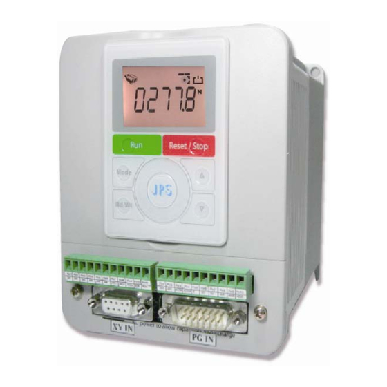
Suit for Induction motor with encoder feedback. PCMD Stndard type. Pulse Command Mode embedded. Indicates that this driver is an Advanced type. Indicates that the control panel of this driver . Description of Control Panel C-Panel R-Panel 220V Indicate the suitable power rating individually. www.jps.com.tw... -
Page 9: The Driver Rating Label
Function Factory Only Panel R Panel INPUT :AC3Ø220 / 50/60HZ Power-Type A.C. 1 or 3 Phase, 220Volt. Power Frequency 50Hz/60Hz OUTPUT : 3Ø5A 2KVA / 0~400Hz Phase / Current 3Phase/5A Capacitance (KVA) 2KVA Output Frequency Range 0 ~ 400HZ www.jps.com.tw... -
Page 10: The Specification Of Iris Series
Horse Power(HP) Rated Capacity(KVA) 0.65 Rated Power(KW) 0.75 22.5 Max Output Voltage(V) Match 3 phase Input Voltage Dimension 380V Series: 4R□ Output Current(A) Horse Power(HP) Rated Capacity(KVA) Rated Power(KW) 22.5 Max Output Voltage(V) Match 3 phase Input Voltage Dimension www.jps.com.tw... -
Page 11: The Specification Of Hardware
1 Unit Analog Input 2 Unit(12bit resolution) Analog Output 1 Unit RS485 Communication Interface 2 Units Fan Malfunction & Precaution Function Included Over Heat Protect Function Included PG Feedback Interface 1Unit Brake Discharge MOS-FET Included External Received Interface 1 Unit www.jps.com.tw... -
Page 12: Condition Of Storage Environment
Please consider the possible use of options, such as RFI suppression filters at the planning stage. WARNING To prevent electrical shock, do not open cover for at least 5 minutes after removing AC power to allow capacitors to discharge. www.jps.com.tw... -
Page 13: Outline Dimension
4.Outline Dimension P1:0.5HP~2HP Unit:mm P2:3HP~5HP Unit:mm P3:7.5 HP~10HP Unit:mm P4:15HP~30HP Unit:mm www.jps.com.tw... -
Page 14: Description Of Wiring
5.2The Control Signal Terminals WARNING! NOTE! All the input/output control signal lines, or remote panel lines and communication lines must be laid separately from the high current power/motor/brake lines. They must not be fed through the same cable conduit/trucking. www.jps.com.tw... -
Page 15: Brake Resistor Terminals
Model Resistance(ohm) Wattage (W) 2R3P5 2R11 2R17 2R24 2R33 2R46 1000 2R61 1500 2R90 2000 4R5P5 4R8P5 4R12 4R17 4R23 1000 4R31 1500 4R45 2000 The discharge duty is 10 % www.jps.com.tw... -
Page 16: The Input Reactor
Voltage (V) Model Current (A) Inductance 1.8mH 2R3P5 1.8mH 1.8mH 1.1mH 2R11 0.71mH 2R17 0.53mH 2R24 0.35mH 2R33 0.26mH 2R46 0.18mH 2R61 0.13mH 2R90 0.09mH 4R5P5 3.6mH 4R8P5 2.2mH 4R12 1.42mH 4R17 1.0mH 4R23 0.7mH 4R31 0.53mH 4R45 0.36mH www.jps.com.tw... -
Page 17: The Proper Screw Drive For Power Terminals
It is necessary to choose proper tool for wiring connection to avoid screw stripped or burst. Please refer to the list below to choose a proper screw drive for driving power terminals. A - B mm C mm D mm P mm L mm 0.6 - 3.3 C mm D mm P mm L mm www.jps.com.tw... -
Page 18: Basic Wiring Diagram For Iris Series Drive
6.Basic Wiring Diagram for IRIS Series Drive POWER SOURCE Filter MOTOR IGBT BRAKE LCD-485 0V ~ +10V RANGE POTENTIAL -10V ~ +10V RANGE METER ACOM ACOM 485-A RY3A TO PLC、 HMI、、、 485-B MAX. RATING 200V, 3A RY3B OPEN COLLECTER PHOTO ISOLATED DIGITAL INPUT PORT www.jps.com.tw... -
Page 19: I/O Interface
DB2(M):PG_IN TM1: Terminal Spec. IEC 130V,8A Digital Input:DI1 ~ DI6。 XY_IN PG_IN Digital Ouput:DO1 ~ DO3。 Signal Voltage Ground:G24。 TM2: Terminal Spec. IEC 130V,8A Voltage Output:4V。 Analog Output:AM1。 Analog Input:AI1、AI2。 Voltage Output:T5V、(ACOM)。 RS485 Communication(485-A,485-B)。 ACOM SHIELD PGND FG SHIELD www.jps.com.tw... -
Page 20: 2Hp】 Input/Output Terminal On Back Side
DB3(M):PG OUT DB3(M):PG_OUT *PG_OUT:use cable with DB9M-SC8P-0.5M。 PG_OUT *DB9M-SC8P-0.5M:Optional。 CON9 9PinD-sub(Male) Signal Pin1 Pin 1 Pin2 Pin 2 Pin3 Pin 3 Pin4 Pin 4 Pin5 Pin 5 Pin6 Pin 6 Pin 7 Pin7 Pin 8 VSS-D Pin 9 Pin8 SHIELD www.jps.com.tw... -
Page 21: 30Hp】Input/Output Terminal On Front Side
Pin5 Pin5 Pin5 N.C. Pin5 Pin5 Cout Pin6 Pin6 Pin6 N.C. Pin6 Pin6 /Cout Pin7 Pin13 Pin5 Pin7 Pin7 N.C. Pin8 Pin14/ Pin15 Pin6 Pin8 Pin7 Pin8 Pin9 Pin9 N.C. Pin9 N.C. Pin10 Pin7 shell shield Pin8 shell shield www.jps.com.tw... -
Page 22: Con6 Comm., Di/O, Ai, Am, Pg_In, Pg_Out, Xy_In Description
Digital Output Open Collector Digital input terminals. +24V (reference ground is G24) To CPU Only be used under 24V voltage DI1 ~ DI6 level to keep system stable. DI-(x) 4.7K Programmable by setting parameter value. Digital Input www.jps.com.tw... - Page 23 The input hardware structure of signal OB+-、OC+- is same as signal OA+-. The XY pulse input hardware structure is design as 5V Line Drive type input. 220,1/4W XY_IN The input hardware structure of signal Y is same as signal X. www.jps.com.tw...
-
Page 24: Xy Signal Input Description
If use 24V Open Collector signal as digital input , Just connect to terminal。 Need to connect limit resistance(2K,1W)。 2K,1W 220,1/4W 220,1/4W +24V ps:Y signal & X signal 。 ps:Y signal & X signal 。 Use 5V Line Driver signal,please refer to: Open Collector Signal,please refer to: www.jps.com.tw... -
Page 25: Quick Start
Setting Pr.003 (Motor Operation Mode) to be 2 (Close Loop Mode.) Reset the driver. Step II Start to Run Setting Pr.120 (Speed Set 0) = 100. Setting Speed Set 0 = 100 rpm. Connect FWD and G24 terminals, the motor will start and run at 100 rpm speed www.jps.com.tw... -
Page 26: Run Command Set From Control Panel
Connect the U, W, V wires to the terminals U, V, W of driver. Change the output power lines. Turn on the AC input power. Setting Pr.188 (Encoder sensor direction) to be 0. Phase A leads phase B. Setting Pr.065 = 73 Redefined the FWD terminal function. www.jps.com.tw... -
Page 27: Parameter Description
9.Parameter Description 9.1 IRIS-IMSV Parameter List Driver Specification Group <Refer to Chapter-10.1> *There is different setting for different model Name Default Min. Max. Unit Type GXX-XX 071 Unit Address FR/W;R 00-00 097 Driver system software version FFFF Version 00-01 130 AC power input voltage... - Page 28 189 ENCODER PPR 256 60000 FR/W;R 07-01 190 ENCODER A/B/Z Status 07-04 191 ENCODER COUNTER 65535 07-05 192 ENCODER DATA FILTER BUFFER FR/W;R 07-03 193 ENCODER CHECK TIME 30000 07-08 194 ENCODER TYPE FR/W;R 354 Actual Counts Per Revolution 65535 www.jps.com.tw...
- Page 29 123 Speed Set3 30000 16-03 124 Speed Set4 30000 16-04 125 Speed Set5 30000 16-05 126 Speed Set6 30000 16-06 127 Speed Set7 30000 16-07 128 Maximum RPM Limit 3000 30000 FR/W 16-08 278 Select Speed Source when SWx=000 R/W;R 16-09 www.jps.com.tw...
- Page 30 108 Torque Droop Range 15-18 110 Directional Limitation FR/W 15-19 160 2'nd Speed Loop Switch point 3000 15-09 161 2'nd speed loop P-gain 1000 15-10 162 2'nd speed loop I-gain 1000 15-11 163 2'nd speed loop filter l 15-12 www.jps.com.tw...
- Page 31 104 Up/Dn Setting Mode 64-00 105 Up/Dn Data Preset Value 3000 64-01 106 Up/Dn Rate ( Trigger active ) 1.00 0.00 300.00 Rpm/Trigger R/W 64-02 107 Up/Dn Rate ( Level active ) 30000 Rpm/Sec 64-03 117 Up/Dn Data Temperary Value 30000 www.jps.com.tw...
- Page 32 297 PID-Gain-Switch Point 0.00 0.00 100.00 DC-BUS adjust Group <Refer to Chapter-10.11> Name Default Min. Max. Unit Type GXX-XX 131 DC bus measurement adjust FR/W 82-00 132 DC bus voltage 1000 82-01 151 Over-Discharge-Protect time 10.0 82-02 159 UP Recovery www.jps.com.tw...
-
Page 33: Monitor Type Parameters' Address
The parameter is Monitor type. Only readable and no effect for writing this parameter. Factory set parameter, and should not be changed. To indicate that any change of this type of parameter have to Reset the driver to enable the change. www.jps.com.tw... -
Page 34: Iris-Imsv Parameter Description
10. IRIS-IMSV Parameter Description 10.1 Driver Specification Group Pr.071 Unit Address (for communication) This parameter can be set from 1 to 63. If there are above 2 driver connected to the communication line, the unit address should be set for individual number. - Page 35 If Pr.368=0, after reset the Pr.368=0. If Pr.368=1, Pr.368=1. Pr.369 Recover Parameters to Default If setting Pr.369 to be 1, all the R/W type parameters in EAROM will be initialized to default value. After changing the value of this parameter, must reset the driver. www.jps.com.tw...
-
Page 36: Digital Input Group
DI16 Function Select (virtual input, links to DO16) DI15 and DI16 are virtual inputs, and are directly links to DO15 and DO16 respectively. 【NOTE】 The digital input function definition can’t be repeated. Check this point after finish setting this group. www.jps.com.tw... -
Page 37: Digital Output Group
Pr.165 DO15 Function Select (virtual output, links to DI15) Pr.166 DO16 Function Select (virtual output, links to DI16) DO15 and DO16 are virtual outputs, and are directly links to DI15 and DI16 respectively. www.jps.com.tw... -
Page 38: Analog Input Group
If Pr.233 select type 0, the AI1 input in the range of Pr.232 +/- Pr.235 will be negated. 【NOTE】Only when Pr.233 select type 1, the function of Pr.235 is available. Pr.488 AI-1 Compare Set Value Setting Pr.488 to compare with Pr.234 AI-1 Command Value。Unit:% www.jps.com.tw... -
Page 39: Analog Input:ai2
If Pr.484 select type 0, the AI2 input in the range of Pr.482 +/- Pr.486 will be negated. 【NOTE】Only when Pr.484 select type 1, the function of Pr.486 is available. Pr.487 AI-2 Compare Set Value Setting Pr.487 to compare with Pr.485 AI-2 Command Value。 Unit:% www.jps.com.tw... - Page 40 If the input voltage of AI1 is in the range of 2014+/-20, the motor will not run. If the input voltage of AI1 exceeds f the range of 2014+/-20, the motor will run, and the min. start speed of motor will be about 30rpm. www.jps.com.tw...
- Page 41 Input min. voltage to AI1, read Pr.229. Write Pr.229 value into Pr.232. Setting AI1 min. value. Setting Pr.278 (Speed Command Select) =1 Select AI1 input as speed command. 10. Reset the driver. Change Pr.278, must reset driver. 485B 485A ACOM ACOM +10V ~ -10V www.jps.com.tw...
-
Page 42: Analog Output Group
Select =14 AM1 send out 12.5% volume for adjusting. The output is adjusted by Pr.377. Select =15 The output of AM1 is set by Pr.372. 【NOTE】After change this parameter, the driver should be reset to let the changes be effect. www.jps.com.tw... - Page 43 Pr.375 AM1 50% Scale Adjustment Be used for AM1 50% output scale adjustment. Pr.376 AM1 25% Scale Adjustment Be used for AM1 25% output scale adjustment. Pr.377 AM1 12.5% Scale Adjustment Be used for AM1 12.5% output scale adjustment. www.jps.com.tw...
- Page 44 Adjust the Pr.377 to let the meter point to 800x12.5%=225. 17. Pr.370=4 Set AM1 function to output motor’s actual speed. 18. Pr.371=1800 Set AM1 full scale data range to be 1800. 19. Execute RESET After reset the driver, the setting of AM1 is finished. www.jps.com.tw...
-
Page 45: Encoder Sensor Group
Pr.194 Encoder type JPS MAG-C Encoder (Recommand) Note:The Encoder type 1 and 2 uses the ABZ to deliver the UVW status within 5 or 500 ms when power on starts. After the 5 or 500ms period, the output signals of ABZ will change to present normal AB phase pulses and Z index. -
Page 46: Imsv Motor Group
Electronic Thermo protect function is disabled. (Irms /Pr.210) 150% 110% Pr.215 TIME Pr.216 RESISTANCE(between V&W, U phase open) Pr.217 INDUCTANCE(between V&W, U phase open) These two parameters should refer to the data of motor’s manufacturer, or can be auto tuned by driver. www.jps.com.tw... -
Page 47: Imsv Control Group
1'st Speed Loop Igain Pr.033 1'st Speed Loop Filter These are the 1’st PI tuning parameter for close loop control. 【NOTE】If Pr.033 set too large, the response will be low, and the system will be unstable. Pr.031 should keep larger then Pr.032. www.jps.com.tw... - Page 48 ※ If Pr.086 select 1: When the motor runs in different guardant, the driver will use different torque limit setting respectively. Q-Ⅱ +Torque Q-Ⅰ Forward Reverse Motor Motor Pr.087 Pr.088 -rpm +rpm +Pr.128 -Pr.128 Pr.089 Pr.090 Reverse Forward Generator Generator Q-Ⅲ -Torque Q-Ⅳ www.jps.com.tw...
- Page 49 The torque is set by AI1 x (Pr.087 Torque Limit-quadrant I). Q-Ⅱ +Torque Q-Ⅰ Forward Reverse Motor Motor +Pr.087 Varied by AI1 -rpm +rpm -Pr.128 +Pr.128 Varied by AI1 -Pr.087 Reverse Forward Generator Generator Q-Ⅲ -Torque Q-Ⅳ ※ If Pr.086 select 9 Torque-limit source=AI2,similar Pr.086 = 1。 www.jps.com.tw...
- Page 50 Torque Compare Level (% of Motor Rated Torque) Set the compared torque value for Over-torque-warning in this parameter. 【NOTE】About the detail, please refer to Chapter 0 12. Digital Output Function. Pr.096 Random Torque Command Setting (RAM) This parameter can set torque-limit percentage 【Note】Suitable Mode Pr.086= 4 www.jps.com.tw...
- Page 51 Permit forward and reverse direction run command. Only forward direction run command is permitted. The reverse direction run command will stop the motor. Only reverse direction run command is permitted. The forward direction run command will stop the motor. www.jps.com.tw...
- Page 52 When speed is in the range of 300 ~ 1500rpm, the driver will change the PI tuning parameters’ value from 1’st to 2’nd by linear manner. When speed exceeds 1500rpm, the driver uses 2’nd PI tuning parameters for close loop control. www.jps.com.tw...
-
Page 53: Imsv Multi-Speed Setting Group
The speed command set from Speed Up / Down Counter output. The speed command set from Pcmd Reserved 11~18 The speed command set from Rotary Switch. The speed command set from AIP (VR of then R-Panel Only) The speed command set from PID Block www.jps.com.tw... -
Page 54: Imsv Acc/Dec/S-Curve Group
Acc. Time Pr.053 = 8.00sec, Dec. Time Pr.054 = 10.00sec. The slope of rising ramp is 1000rpm/8sec; the slope of falling ramp is 1000rpm/10sec. Therefore, from 0 to 1000rpm need 8+4 = 12sec; from 1500 to 0rpm need 10+5 = 15sec. www.jps.com.tw... - Page 55 Ta (totally acc. time) = (0.5 x S-curve T1 Time) + (Acc. Time) + (0.5 x S-curveT2 Time) = 2sec. Pr.289 START OPTION SELECT Value Description Select start speed from zero speed Select start speed from current speed Pr.290 START DELAY TIME Setting START DELAY TIME www.jps.com.tw...
- Page 56 When driver decelerate to 0 speed, it will send a brake voltage to motor and hold for a period of time to make sure the motor actually stopped. This time is called Brake Hold Time. Speed Output Brake Voltage Pr.054 Pr.291 www.jps.com.tw...
-
Page 57: Dc-Bus Adjust Group
This parameter displays the temperature of the driver’s heat sink. Pr.150 Over Heat Protect Temperature (centigrade) When the heat sink temperature (displays in Pr.140) exceeds the setting of this parameter, the driver will trip and show the OH alarm message. www.jps.com.tw... -
Page 58: Fan Adjust Group
If set Pr.149 to be 2000rpm, and set DOx(11). When fan speed is lower then 2000rpm, the output terminal will have warning signal output, when fan speed is lower then 1000rpm, the driver will trip and show CF alarm message. FAN Speed FAN RPM=2000 FAN RPM=1000 DOx(11) CF Alarm www.jps.com.tw... -
Page 59: Digital Input Function
FWD + DIx(76) REV + DIx(76) Set Flip-Flop (1) Set Flip-Flop (2) Clear Flip-Flop(1) Clear Flip-Flop(2) Set T-Type Flip-Flop (1) 13.2 Set T-Type Flip-Flop (2) Set Data Flip-Flop (1) Set Data Flip-Flop (2) Set Ck Flip-Flop (1) Set Ck Flip-Flop (2) www.jps.com.tw... - Page 60 PCMD-> X/Y input simulation enable(Refer to Carrier) PCMD-> Vcmd change to Pcmd PCMD-> Pcmd change to Vcmd 14.4.2 PCMD-> Pcmd Direction Select PCMD-> Pcmd Input Clocks Enable PCMD-> Pcmd Input Clocks Enable + XYM online change Emergency Stop (will cause ES trip) www.jps.com.tw...
- Page 61 The priority of these two function is: DIx(21) > Pr.059. DIx _ Select 23, Reset If the input is active, the driver will be reset by this signal. 【NOTE】This function only can be selected only by actual terminal, for virtual terminal can not select this function. www.jps.com.tw...
- Page 62 If the input is active, the driver will drive motor to reverse direction. DIx _ Select 75, Change Running Direction If the input is active, the driver will change the motor direction. The figure below shows how to use the function of 73, 74, and 75. +rpm -rpm DIx(73) DIx(74) DIx(75) www.jps.com.tw...
- Page 63 249,Emergency Stop (will cause ES trip) If the input is active, the driver will: The driver will immediately trip and stop output to motor. Motor will have no power and free run to stop. The driver will show ES alarm message. www.jps.com.tw...
-
Page 64: Digital Output Function
Over Torque Warning ACCing DECing ABS(AI2 Command Value ) > AI2 Compare Set Value ABS(AI1 Command Value ) > AI1 Compare Set Value Timer A output “Q” Timer A output “/Q”. 13.3 Timer B output “Q” Timer B output “/Q”. www.jps.com.tw... - Page 65 97,ABS(AI2 Command Value ) > AI2 Compare Set Value When AI2 command value(Pr.485)> AI2 compare set value(Pr.487),output status will be active。 DOx_Select 98,ABS(AI1 Command Value ) > AI1 Compare Set Value When AI1 command value(Pr.234)> AI1 compare set value(Pr.488),output status will be active。 www.jps.com.tw...
-
Page 66: Flip-Flop Function Description
27,Pulse_Frequency-1 > COMPARE-Set1 Active when (Pr.243:Pulse_Frequency-1)>(Pr.246:COMPARE_SET-1)。 DOx_Select 28,Pulse_Frequency-1 > COMPARE-Set2 Active when (Pr.244:Pulse_Frequency-2)>(Pr.247:COMPARE_SET-2)。 DOx_Select 29,Pulse_Frequency-1 > COMPARE-Set3 Active when (Pr.245:Pulse_Frequency-1)>(Pr.248:COMPARE_SET-3)。 DOx_Select 31,Pulse-Counter-1 > COMPARE-Set1 Active when (Pr.240:PULSE_COUNTER-Mon1)>(Pr.246:COMPARE_SET-1)。 DOx_Select 32,Pulse-Counter-1 > COMPARE-Set2 Active when (Pr.241:PULSE_COUNTER-Mon2)>(Pr.247:COMPARE_SET-2)。 DOx_Select 33,Pulse-Counter-1 > COMPARE-Set3 Active when (Pr.242:PULSE_COUNTER-Mon3)>(Pr.248:COMPARE_SET-3)。 www.jps.com.tw... -
Page 67: Flipflop Group
88, Set Ck Flip-Flop (1) DIx _ Select 89, Set Ck Flip-Flop (2) 13.2.3 FlipFlop Group Digital-Output DOx _ Select 80, Flip-Flop(1) Output DOx _ Select 82, Flip-Flop (1)Reverse Output DOx _ Select 81, Flip-Flop(2) Output DOx _ Select 83, Flip-Flop (2)Reverse Output www.jps.com.tw... -
Page 68: General Flip-Flop
The driver contains the general Flip-Flop.In each Flip-Flop needs two input,and two output Two input set to DIx(80) and DIx(82) Two outout set to DOx(80) and DOx(82) Relationship: When trigger DIx(80),DOx(80) output ON。 When trigger DIx(82),DOx(80) output OFF。 ※ DOx(82) opposite DOx(80) output。 www.jps.com.tw... -
Page 69: D-Type Flip-Flop
Truth Table:(D Type Flip/Flop) STEP Reset ↑ ↑ X: Don’t Care DI-x(86) DI-x(88) DI-x(80) DI-x(82) DO-x(80) DO-x(82) When trigger DIx(88),show DIx(86) status to DOx(80) 。 When trigger DIx(80),then DOx(80) output ON。 When trigger DIx(82),then DOx(80) output OFF。 DOx(82) opposite DOx(80) output。 www.jps.com.tw... -
Page 70: T-Type Flip-Flop
DO-x(80) DO-x(82) When trigger DIx(80),DOx(80) output is ON。 When trigger DIx(82),DOx(80) output is OFF。 When trigger DIx(84),all status opposite and show to DOx(80) 。 When trigger DIx(80),then DOx(80) output ON。 When trigger DIx(82),then DOx(80) output OFF。 DOx(82),opposite DOx(80) output。。 www.jps.com.tw... -
Page 71: Timer Group
Define the action time of the timer; for Timer A use Pr.250 and Pr.251, for Timer B use Pr.253 and Pr.254. Define a DI to be the Enable input of timer. Define a DO to be the output of timer. www.jps.com.tw... -
Page 72: Timer Function (Delay Off Mode)
When DIx(61) ON, DOx(106) becomes OFF, and after T1 time, it becomes ON; when DIx(60) becomes OFF, T1 time, it becomes ON; when DIx(61) becomes OFF, DOx(104) becomes OFF immediately. DOx(106) becomes OFF immediately. DOx(105) is opposite to DOx(104). DOx(107) is opposite to DOx(106). www.jps.com.tw... -
Page 73: Timer Function (Auto On/Off Mode)
T1 determine the ON timing, T2 determine the OFF timing. When DIx(60) becomes OFF, the OFF timing. When DIx(61) becomes OFF, DOx(104) becomes OFF immediately. DOx(106) becomes OFF immediately. DOx(105) is opposite to DOx(104). DOx(107) is opposite to DOx(106). www.jps.com.tw... -
Page 74: Speed Compare Group
When the output terminal function selection mode, function SPNA (Speed Not Arrive: ) The terminal must start forward or reverse the state, and when the drive Pr.19: actual speed - Set the speed> = Pr.208, the terminal output ON. www.jps.com.tw... -
Page 75: Speed Up / Down Counter
This parameter defines the change volume that will be changed for Speed Up / Down Counter when every trigger happened. When trigger DIx(91), the counter will increase a volume of Pr.106. When trigger DIx(92), the counter will decrease a volume of Pr.106. www.jps.com.tw... - Page 76 When DIx(93) is ON, the counter will increase a volume of Pr.107 in every second. When DIx(94) is ON, the counter will decrease a volume of Pr.107 in every second. Pr.117 Up/Dn Data Temperary Value This parameter display Up/Dn Result value。 www.jps.com.tw...
-
Page 77: Speed Up/Down Counter Digital-Input
94,Up/Down Buffer Level- DEC Decrease the Speed Up / Down Counter by a preset value in Pr.107 every second. DIx _ Select 95,Up/Down Buffer "SAVE Buffer to Pr.105" Save Speed Up / Down Counter value into Pr.105. 13.5.3 Speed Up/Down Counter Digital-Ouput www.jps.com.tw... -
Page 78: Pulsetype-Speed Up/Down Counter
When DIx(90) is trigged, the output of counter will be cleared to 0. When DIx(92) is trigged, the output of counter will decrease a value of Pr.106. When DIx(95) is trigged, the value of counter will be stored into Pr.105. www.jps.com.tw... -
Page 79: Level Type-Speed Up/Down Counter
When DIx(90) is trigged, the output of counter will be cleared to 0. When DIx(94) is trigged, the output of counter will decrease a value of Pr.107 for every second. When DIx(95) is trigged, the value of counter will be stored into Pr.105. www.jps.com.tw... -
Page 80: Rotary Switch Group
DIx _ Select 205,Rotary Switch signal-Store input. This function defines the terminal to be the input of Rotary Switch pulse count store; when this function is active, the value in Pr.137 (RSW Data) will be stored into Pr.138 (RSW Backup Memory). www.jps.com.tw... -
Page 81: Rotary Switch Group Digital-Output
10. Start to run forward and the drive will run in the speed that set by Rotary Switch. If the Rotary Switch is see in 500, the speed will be Pr.137 / Pr.152 * Pr.128 = 1000rpm. 11. Press the Store bottom, the value in Pr.137 will be stored into Pr.152. www.jps.com.tw... -
Page 82: Pid Function
Keep value after reset or power off Use AI1%,as PID set, AI1 as Set Data (Pr.234) AI1data can check with Pr.236 Actual Speed(normalized) Use actual speed,as PID set as Set Data RSW as Set Data Use RSW(Rotary Switch Data) as PID set, (100%*Pr.137/152) Resolution=(100%×Pr.137/Pr.152) www.jps.com.tw... - Page 83 When (Actual speed / Max speed)× 100% between XX.YY use linear gain of PID1/PID2 ※ YY shoulde be larger then XX,if YY > XX,driver will set YY as switch point of PID2 ,and set XX as switch point of PID1。 www.jps.com.tw...
-
Page 84: Pid Function Digital-Input
Pr.296:PID I - gain2 = 10 ※ When actually speed > 800rpm,main gain = PID- Gain1 ※ When actually speed < 200rpm,main gain = PID-Gain2 ※ When actually speed between 200rpm ~ 800rpm,main gain = linear adjustment。 1000 PID High Gain PID Low Gain www.jps.com.tw... -
Page 85: Pcmd Mode
DB3(M) PG Output To Slave Input Line speed DB2(M) PG Input To Encoder DI-1(220) Enable Simulated XY input pulse DI-2(222) Switch to Speed Command Mode DI-3(223) Change XY input pulse direction DI-4(224) Enable Pulse Command mode DI-5(73) Forward Run www.jps.com.tw... -
Page 86: Pcmd Function Block
Pr.278=10 Pulse CMD Mode Pr.450 XY MULTIPLY Pr.399 X/Y XY Pulse Pr.451 XY DIVIDE Input Direction Pr.456 XY MULTIPLY Execute-Value(RAM) Pr.452=0 XY QEP Type Pr.452 XY Command Type Pr.452=1 X: Enable Y:CKinput Pr.396 PCMD: Position Servo-Gain Actual Position CMD www.jps.com.tw... -
Page 87: Pcmd Function Group
X/Y Commad Type Tow phase pulse train. A pulse clock train and a direction indicae signal. Y input is clock train. Using DIx(223) to accept the direction indicate signal. DIx(223) 【Note】The variation will be effected only after the drive is resetted. www.jps.com.tw... - Page 88 XY Multi factor parameter,belong to RAM type,change this parameter will change Pcmd Factor immediately。 【Note】This parameter will be put by program after reset every time。 Allow on-line change。 Pr.470 Position Tracking Error This parameter displays tracking error when Pcmd activity。 www.jps.com.tw...
-
Page 89: Pcmd Group Digital Input
226,PCMD-> Pcmd Input Clocks Enable + XYM online change When set “ON”,enable Pcmd enabled and XY-online adjustment。 When set “OFF”,not allow any external command,drive stop running。 【Note】when eable this function i,program allow Pr.450 setting value。 14.4.3 PCMD Group Digital Output www.jps.com.tw... -
Page 90: Pcmd Function Basic Example
【Note】If the motor runs in forward direction, the drive is operating correctly and might go on next step; if not, check all settings. DI1(220): Disable Simulated XY input pulse > Keep in “OFF” state 【Note】In this moment, the pulse train from XY inpu port will decide the speed of motor. www.jps.com.tw... -
Page 91: Alarm Message And Maintenance
Because the reason of this problem may includes magnetic sensor, therefore, before sending the driver for maintenance, it is better to replace the driver with another good condition one to make sure the problem is caused by driver individually. www.jps.com.tw... - Page 92 Is there any interference to cause the signal happened? If the emergency condition is indeed, contact with the system engineer to fix the condition. Unless the emergency condition is fixed completely, the driver shouldn’t be operated to run the motor. www.jps.com.tw...
- Page 93 Check if the condition of driver fit in the installation environment. Check if the ambient temperature exceeds the installation environment. The temperally variation of climate may cause ambient temperature to be high, arranging a proper cooling method to prevent over heat contition is necessary at this moment. www.jps.com.tw...
- Page 94 If the OC happened in the decelerating period, try to increase the setting of Pr.054 (Dec Time). Check if the setting of Pr.130 (Input AC Power Voltage) is correct or not. Check if the displayed message of Pr.132 (DC Bus Voltage) is correct or not. www.jps.com.tw...
-
Page 95: Ce Certificate
16. CE Certificate 16.1 EMC Certificate www.jps.com.tw... -
Page 96: Lvd Certificate
16.2 LVD Certificate www.jps.com.tw... -
Page 97: Control Panel Description
The output frequency. Output current. Output voltage. To run or stop the motor twice monitor mode When in Press (within 0.5sec) Will start the motor to run, or twice monitor mode Press When in (within 0.5sec) Will stop the motor. www.jps.com.tw... -
Page 98: Use The Fly Wheel Function In The Monitor Mode
Using up/down keys to change the value press to change the value. Bothe of these two ways can be used to change the value. Write twice within 0.5sec, the value will be written into Press memory. www.jps.com.tw... -
Page 99: Parameter Mode (Select, Read, Edit, Write)
By processes, least digital of displayed data will be flashed to indicate that is ready to be edit. Change the edit position Touch the left to change the edit or right position. Enter parameter number Press to increase or decrease value. to change the value. Draw on the fly wheel circularly www.jps.com.tw... -
Page 100: Reset Function
A0 A1 A2 A3, and the record A0 will be refresh by present status. 17.1.6 RESET Function Twice within 0.5sec. mode Press This procedure will reset the driver and panel itself, and the effect like power-on restart. www.jps.com.tw... -
Page 101: R-Panel Operational
The function description of buttons is as below: 【FWD】: Motor RUN Forward command (DI5 ON; DI6 OFF) 【REV】: Motor RUN Reverse command (DI5 OFF; DI6 ON) 【STOP】: Motor STOP command (DI5 OFF; DI6 OFF) 【▲】: Change monitor parameter. 【▼】: Change monitor parameter. www.jps.com.tw... -
Page 102: Parameter Editing Mode 【Par Mode
Continuously press "PAR/ALM," if the display shows "A0-xx," the drive is under “ALM MODE.” User can observe last four alarm record or RESET drive under this mode. Press ▲ or ▼ to see historical alarm record. Press "STOP/RESET," to reset drive. www.jps.com.tw... -
Page 103: Rd / Wt【Single-Word】/【Double-Word】Parameters
Press ▲, ▼ , or “STOP” button to change the value. The display is flashing on this time. After deciding the value, press “RD/WT” button to write down the value. The display stop flashing means the value written down. www.jps.com.tw... -
Page 104: Single-Word】/【Double-Word】Negative Numbers
Under this status, if the value is positive 1 LED lit up. ※ Edit status means one of the seven-segment displays flashing. ※ STOP button works only when parameters are sighed. ※ If 1 Led lit up, the value is positive. ※ If 1 Led flashing, the value is negative. www.jps.com.tw... -
Page 105: Alarm Mode Of R-Panel【Alm Code Description
Over Current A0 - OC Current output over protection level A0 – Er. Communication Fail A0 – Er. Communication between panel and drive failed 17.2.8【Definition of Cables】 JAM SC-5P Connector: Pin5 Pin1 PIN1 PIN2 PIN3 485-A PIN4 485-B PIN5 X(NC) www.jps.com.tw... - Page 106 (2 22 )6 F. , N o.2 6 6, S ec .3 , Pe i sh en Ro ad , Sh en K e ng s hi an g, Ta ip ei Hs ie n, Ta iw a n TEL:886-2-26646866 FAX:886-2-26644889 ht tp :/ /w w w.jps .c om .t w www.jps.com.tw...
Need help?
Do you have a question about the IRIS-IMSV and is the answer not in the manual?
Questions and answers