Sign In
Upload
Manuals
Brands
JPS Manuals
Controller
IRIS-IMSV
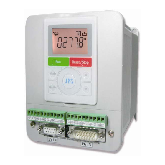
JPS IRIS-IMSV Manuals
Manuals and User Guides for JPS IRIS-IMSV. We have
1
JPS IRIS-IMSV manual available for free PDF download: User Manual
JPS IRIS-IMSV User Manual (106 pages)
Brand:
JPS
| Category:
Controller
| Size: 1 MB
Table of Contents
Table of Contents
4
Production Introduction
8
Check Items
8
Description of Nameplate Content
8
The Label on the Packing Case
8
The Driver Rating Label
9
The Specification of IRIS Series
10
1The Rating
10
The Specification of Hardware
11
Condition of Storage Environment
12
Attention of Installation
12
Outline Dimension
13
Description of Wiring
14
Power Terminal
14
1The Power Input Terminals (R, S, T)
14
2The Output Terminals (U, V, W to Motor)
14
The Control Signal Terminals
14
Brake Resistor Terminals
15
The Input Reactor
16
The Proper Screw Drive for Power Terminals
17
Basic Wiring Diagram for IRIS Series Drive
18
I/O Interface
19
The Map of I/O Terminal Position
19
2Hp】Input/Output Terminal on Front Side
19
2HP】 Input/Output Terminal on Back Side
20
30Hp】Input/Output Terminal on Front Side
21
Definition of Control Signals
21
CON6 Comm., DI/O, AI, AM, Pg_In, Pg_Out, Xy_In Description
22
XY Signal Input Description
24
Quick Start
25
Run Command Set from Digital Input Terminals
25
Step II Start to Run
25
RUN Command Set from Control Panel
26
R-Panel Operation Method
26
C-Panel Operation Method
26
Change the Definition of Motor's Direction
26
Parameter Description
27
IRIS-IMSV Parameter List
27
Monitor Type Parameters' Address
33
Parameter's Type
33
IRIS-IMSV Parameter Description
34
Driver Specification Group
34
Digital Input Group
36
Digital Output Group
37
Analog Input Group
38
Analog Input:ai1
38
Analog Input:ai2
39
Analog Output Group
42
Encoder Sensor Group
45
IMSV Motor Group
46
IMSV Control Group
47
IMSV Multi-Speed Setting Group
53
IMSV Acc/Dec/S-Curve Group
54
DC-BUS Adjust Group
57
Thermistor Adjust Group
57
FAN Adjust Group
58
Digital Input Function
59
Digital Output Function
64
Flip-Flop Function Description
66
Pulse-Couter Group
66
Pulse-Counter Parameters
66
Pulse-Counter Digital Input
66
Pulse-Counter Digital Output
66
Flipflop Group
67
Flipflop Group Parameters
67
Flipflop Group Digital-Input
67
Flipflop Group Digital-Output
67
General Flip-Flop
68
D-Type Flip-Flop
69
T-Type Flip-Flop
70
Timer Group
71
Timer Group Parameters
71
Timer Group Digital-Input
71
Timer Group Digital-Output
71
Timer Function (Delay off Mode)
72
Timer Function (Delay on Mode)
72
Timer Function (Auto On/Off Mode)
73
Speed Compare Group
74
Speed Compare Group Parameters
74
Speed Compare Group Digital-Input
74
Speed Compare Group Digital-Ouput
74
Speed up / down Counter
75
Speed Up/Down Counter Parameters
75
Speed Up/Down Counter Digital-Input
77
Speed Up/Down Counter Digital-Ouput
77
Pulsetype-Speed Up/Down Counter
78
Level Type-Speed Up/Down Counter
79
Rotary Switch Group
80
Rotary Switch Group Parameters
80
Rotary Switch Group Digital-Input
80
Rotary Switch Group Digital-Output
81
PID Function
82
PID Function Parameters
82
PID Function Digital-Input
84
PID Function Digital-Output
84
PID Function Block
84
PCMD Mode
85
PCMD Rule
85
PCMD Connection
85
PCMD Function Block
86
PCMD Function Group
87
PCMD Group Parameters
87
PCMD Group Digital Input
89
PCMD Group Digital Output
89
PCMD Function Basic Example
90
PCMD Parameter Setting
90
PCMD Start
90
Alarm Message and Maintenance
91
Display of Alarm Message
91
Maintenance of Alarm Message
91
CE Certificate
95
EMC Certificate
95
LVD Certificate
96
Control Panel Description
97
C-Panel Operational
97
Lock and Unlock
97
Change Mode
97
Monitor Mode
97
Use the Fly Wheel Function in the Monitor Mode
98
Parameter Mode (Select, Read, Edit, Write)
99
RESET Function
100
R-PANEL Operational
101
Control Mode 【CTL MODE
101
Monitor Mode 【MON MODE
101
Parameter Editing Mode 【PAR MODE
102
Alarm Mode【Alm Mode
102
RD / Wt【Single-Word】/【Double-Word】Parameters
103
Single-Word】/【Double-Word】Negative Numbers
104
Alarm Mode of R-Panel【Alm Code Description
105
Definition of Cables
105
Advertisement
Advertisement
Related Products
JPS 5160-410000
JPS Z2 Controller
JPS Categories
Gateway
Recording Equipment
Inverter
Control Panel
Controller
More JPS Manuals
Login
Sign In
OR
Sign in with Facebook
Sign in with Google
Upload manual
Upload from disk
Upload from URL