Table of Contents
Advertisement
Quick Links
INTEROPERABILITY NOW
Installation and Operation Manual
TM
Z2 Controller
Scalable Interoperability /
Dispatch Solution
JPS Interoperability Solutions
5800 Departure Drive
Raleigh, NC 27616
919-790-1011
sales@jpsinterop.com
/
support@jpsinterop.com
www.jpsinterop.com
Manual is JPS P/N 5160-400200
Revision 1.1
©March 2021
Advertisement
Table of Contents

Subscribe to Our Youtube Channel
Related Manuals for JPS Z2 Controller

Summary of Contents for JPS Z2 Controller
- Page 1 INTEROPERABILITY NOW Installation and Operation Manual Z2 Controller Scalable Interoperability / Dispatch Solution JPS Interoperability Solutions 5800 Departure Drive Raleigh, NC 27616 919-790-1011 sales@jpsinterop.com support@jpsinterop.com www.jpsinterop.com Manual is JPS P/N 5160-400200 Revision 1.1 ©March 2021...
- Page 2 PROPRIETARY STATEMENT The information contained in this manual is the property of JPS Interoperability Solutions and is intended for the purchaser’s use only. It may not be reproduced without the expressed written consent of JPS Interoperability Solutions.
-
Page 3: Table Of Contents
IP A VIA USB DDRESS ETERMINATION AND HANGE PORT 3.3.2 IRMWARE PDATE SECURITY - USER TYPES AND PERMISSIONS ..............4-1 Z2 CONTROLLER CONFIGURATION ..................5-1 5.1 V JPS B IP C ................5-1 IRTUAL RIDGE AND HANNELS 5.1.1 IRTUAL HANNELS... - Page 4 6.3.2 6-17 ISPATCH OURCE 6.3.3 6-18 ISPATCH ESOURCE 6.3.4 6-18 6.3.5 6-19 ONITORS 6.4 L ...................... 6-21 TATUS NFORMATION RECENT UPGRADES TO THE Z2 CONTROLLER ..............7-1 7.1 N ......................7-1 PDATED EATURES Z2C Installation and Operation Manual Interoperability Now...
- Page 5 WAN IP address. NXU-2B Network Extension Unit. A JPS device that interfaces a radio or other 4-wire device to other communications devices over an IP network. An NXU-2B uses RoIP. (Previous version NXU-2A).
- Page 6 Z2 Controller Operations Manual Glossary Receiver or Receiving. Session Initiation Protocol. A flexible, standards-based, open protocol that initiates and manages communications between devices over an IP network. Often used to make VoIP calls. Soft Phone A computer with software allowing it to be used as a VoIP phone.
-
Page 7: Overview
JPS RoIP (Radio over IP) products, such as the NXU‑2B, the ACU-2000, the ACU-M, etc., as well as with JPS’ new Z series of products, including the RSP-Z2 and the ACU‑Z1. Features like simplified dispatch capability, monitoring by non-dispatch channels, and IP recorder integration provide enhanced functionality, making the Z2 Controller an adaptable solution to a diverse array of interoperability and communications uses. -
Page 8: Important Definitions
– such as a radio connected to an NXU‑2B or a DSP‑2 card on an ACU 2000 – to the Z2 Controller using JPS RoIP. They may also be used to interface to a Push-to-Talk application such as JPS VIA. Optional encryption licenses are available for added security. -
Page 9: Interoperability And Dispatch
IP recorder for non-evidentiary recordkeeping and playback. • Manage users/permission, set up and verify Z2 Controller network configuration, and configure channels easily using the browser-based GUI and its built-in help text. - Page 10 PTT over Cellular Talkgroups. These channels are all interfaced to the system via four RSP-Z2 units using Bridge channels and one NXU-2B that uses JPS RoIP. Note that each of the JPS VIA Talk Groups requires a dedicated RSP-Z2 channel, which is interfaced to the JPS VIA server and adapts the JPS VIA channel into a format recognizable to the Z2C.
-
Page 11: Specifications
HTTP for browsing. Uses JPS Bridge Channels to control audio streams from RSP-Z2 units and other devices, such as the ACU-Z1 or MCC-4 Desktop Console. Uses JPS RoIP (Radio over IP) to control audio streams from RoIP devices such as the NXU-2B. -
Page 12: Optional Equipment: Not Supplied
To be recognized, a headset must be plugged into a USB port before the power is turned on. The MCC-4 Desktop Console (and the single-channel MCC-1) has integrated JPS Bridge Channels, so it can connect remotely to a Z2 Controller in the same way that RSP-Z2 channels connect. -
Page 13: Installation
If the Z2 Controller unit must be returned, an RMA (Returned Material Authorization) number must first be obtained from JPS. This number must be noted on the outside of the packing carton and on all accompanying documents. When packing the unit for reshipment, it is best to use the original packaging for the unit;... -
Page 14: Installation Considerations
2.5 Mechanical Package The Z2 Controller is housed in an aluminum enclosure, 1.5”H x 7.75”W x 6.5”D (38 x 200 x 160 mm). The unit weighs 2.0 lbs (900 gr). The bottom panel of the unit includes a set of 6-32 flush nuts to allow the Z2C to be mounted to a tray or other flat surface. -
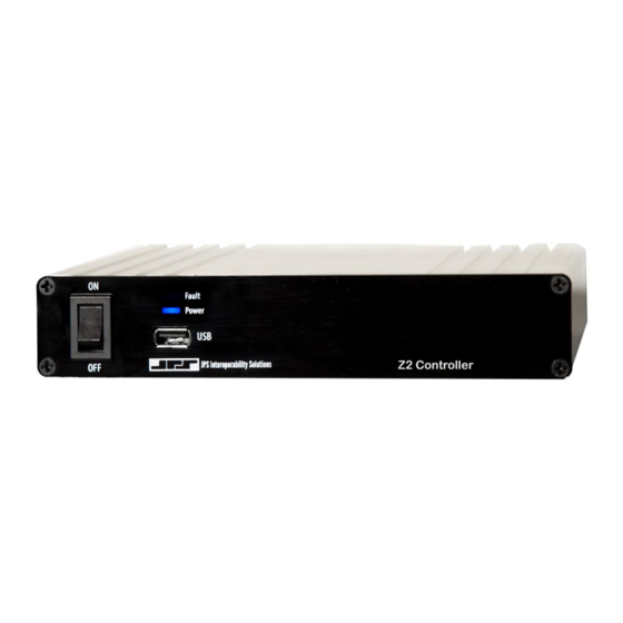
Page 15: Connectors, Controls, And Indicators
On the Z2C front panel are: • The power on/off switch • A USB port that can be used for configuration and with JPS-specified USB wired and wireless headsets. See Optional Equipment: Not Supplied, Section 1.5 • Power and Fault LEDs On the Z2C rear panel are: •... -
Page 16: Power Source
2.8 Safety Precautions and Procedures The Z2 Controller is operated by a +12 VDC power supply and therefore any high-level power supply voltage exists only on the AC input side of the power supply. Standard precautions relative to 115 or 230 (nominal) AC wiring applies. -
Page 17: Web-Based Configuration
3.1 Initial Log In - Set up IP Address and Subnet Mask As with any device with a static IP address, it will be necessary to set up the Z2 Controller to operate on the LAN where it is to be deployed. The first step is to log in using the unit’s factory default IP address of 192.168.1.200, with a default subnet mask of 255.255.255.0. -
Page 18: Network Configuration
3.3.1 IP Address Determination and Change VIA USB port If unable to access the Z2 Controller because you’ve forgotten its IP address and other network settings, the front panel USB port can be used to retrieve the needed information. Plug a thumb drive into the port and cycle the power. -
Page 19: Firmware Update
Interfering with this process can render the unit inoperable Navigate to the Z2 Controller GUI, click on the set of three lines at the top right to bring up a set of icons pertaining to various “housekeeping” functions, then click on the wrench icon to bring up the green Upload new Firmware icon as shown below to the right. - Page 20 Z2 Controller Operations Manual Figure 3-4: Upload Procedure Feedback The screenshot above appears after the new firmware has been updated and installed. However, the process is not complete until the unit has rebooted itself. The time can vary extensively, depending on how major the update is, but is usually under 5 minutes.
-
Page 21: Security - User Types And Permissions
Z2 Controller Operations Manual 4 Security - User Types and Permissions Click Security in the top banner to display the drop-down menu containing the options User Types and Users. Access these pages to set User Types, define user roles and permission, and add or edit users. - Page 22 Z2 Controller Operations Manual To see a list of users, click Security in the top banner and choose Users. The Users page displays a list of users and provides options for adding a user, changing a username, and changing a user password.
-
Page 23: Z2 Controller Configuration
JPS VIA PTT over Cellular Talkgroups. These disparate audio systems are all interfaced to the Z2 Controller via four RSP-Z2 units using JPS Bridge channels and one NXU-2B that uses JPS RoIP. Refer to the diagram on the next page: •... - Page 24 RSP-Z2s and NXU-2Bs. • JPS Bridge channels are available on newer JPS products, such as this unit as well as other Z-series products, and on some third-party devices, such as the...
-
Page 25: Summary Of Steps To Add A Virtual Channel
The following sections of this manual contain instructions for completing the above four steps. Whether you are adding a virtual JPS Bridge or a JPS RoIP streaming channel, the first step is to add the channel to the Z2C’s Expansion Bridge Table, located on the Bridges tab. - Page 26 Port assignments are automatically entered, but may be changed as desired, per restrictions outlined below. • The Port on the Expansion Bridge table will be used by the virtual JPS Bridge or JPS RoIP streaming channel configured on the device connecting to the Z2C. Therefore, all Port numbers must be different.
-
Page 27: Individual Virtual Bridge Channel Configuration
5.1.4 Individual Virtual Bridge Channel Configuration To use a virtual JPS Bridge channel, you will (1) configure it on the Z2C, (2) configure it on the remote resource, (3) authorize it on the remote resource, and (4) connect the remote resource to the Z2C. - Page 28 Encryption Type, and enter an Audio Encryption String composed of letters, numbers, spaces, and/or symbols. Note that the Enable Audio Encryption option is provided on a channel-by- channel basis for JPS Bridge and JPS RoIP channels, and it does not need to be enabled on every channel.
- Page 29 Continue through the next sections for instructions. Note that the Z2C’s IP address (located in the Network tab) will be required, as will the JPS Bridge channel port numbers in the Expansion Bridge table on the Bridges tab, so it will be helpful to have them available.
- Page 30 Figure 5-5: RSP-Z2 Independent Passthrough Configuration with JPS Bridge Backhaul In order to stream from the backhaul JPS Bridge channel to the Z2C, the backhaul channel must be configured properly on the RSP‑Z2. Right click the JPS Bridge channel icon or select Channel from the Settings tab.
- Page 31 (Z2C and the remote unit) match. If there is a mismatch, audio will be unintelligible. The remaining settings for the JPS Bridge channel on the RSP‑Z2 are shown and explained below. Figure 5-6: RSP-Z2 to Z2C Connection Settings There is a single local Network Setting;...
-
Page 32: Individual Jps Roip Streaming Channel Configuration
Z2C. 5.1.5 Individual JPS RoIP Streaming Channel Configuration To use a JPS RoIP channel, you must (1) configure it on the Z2C and (2) configure it on the remote resource. Refer to the following. - Page 33 Encryption Type, and enter an Audio Encryption String composed of letters, numbers, spaces, and/or symbols. Note that the Enable Audio Encryption option is provided on a channel- by-channel basis for JPS Bridge and JPS RoIP channels, and it does not need to be enabled on every channel.
-
Page 34: Licensed Enhancements
When the link is active, a green light will display on the remote resource’s channel icon on the Z2C. Note that regardless of the JPS product you are linking to the Z2C using a JPS RoIP streaming channel, the basic setup outlined here is the same. Refer to the manual of the device you are connecting if you are unsure of how to stream audio from it. - Page 35 Figure 5-9: To Enter License Key Apply. Figure 5-10: AES-256 and HC-128 Encryption Licensed For additional information on JPS RoIP and JPS Bridge channel configuration and encryption, refer to Section 5.1.4.1 Bridge Channel Configuration on the Z2C and Section 5.1.5.1...
-
Page 36: Headset Channel Configuration In The Z2 Controller
5.3 Headset Channel Configuration in the Z2 Controller If a JPS-approved USB Headset is plugged into one of the USB ports prior to unit being powered on, the headset will show up as Local System Resource on the top left of the Home Screen, as shown below. -
Page 37: Usb Headset Settings
Channel Profiles are very useful for Radio Channels in the RSP-Z2, but they have limited utility in the Z2 Controller. For headsets, the automatic USB Headset settings are normally preferred. However, profiles operate in the same manner as with the RSP-Z2. See the RSP-Z2 Installation and Operation Manual located under Help for full information about profiles. -
Page 38: Audio Priority
Z2 Controller Operations Manual Figure 5-13: USB Headset Settings VOX uses the level of audio present in the microphone to determine when COR is active. Note that VOX is required if the headset has an in-line PTT button. Generally, when PTT is selected instead, the VOX Threshold and Hangtime settings don’t come into play. - Page 39 Figure 5-14: Audio Priority Settings Box A potential use to illustrate the function involves a Z2 Controller wide area system consisting of multiple radios and other voice resources, with the USB headset (or any other device) used as the Dispatch Source for some of the radio channels, with a higher priority assigned to the headset.
- Page 40 Z2 Controller Operations Manual 5.4.1 Configuring the MCC Console JPS Bridge Channel(s) on the Z2C The MCC-4 and MCC-1 Consoles are represented by Bridge channels on the Z2C. Therefore, for each channel on the console you want to use, create a corresponding Bridge channel for it on the Z2C.
- Page 41 Z2 Controller Operations Manual Figure 5-16: Configure Recorder Channel The Recorder interface on the Z2C currently only supports unicast RTP connections. JPS has partnered with the Stancil Corporation to test and verify functionality with the Stancil Logging Recorder; however, other recorders that support unicast RTP streams should function with little to no issue.
- Page 42 Z2 Controller Operations Manual Figure 5-17: Example Stancil Logging Recorder Channel Configuration As shown in the next screenshot, to set up a Recording Channel on the Z2C that will stream to the associated Recorder channel, change the preferred codec to match, and enter the IP address and port number of the IP Recorder/channel in the Destination IP Address field.
- Page 43 Z2 Controller Operations Manual Figure 5-18: Recorder Channel Configuration on Z2C End of Section Five Interoperability Now 5-21 Z2C Installation and Operation Manual...
- Page 44 Z2 Controller Operations Manual Blank page for your notes Z2C Installation and Operation Manual 5-22 Interoperability Now...
- Page 45 The USB headset, which was plugged in prior to power-up, is located in the Local Resources section. Below that are the configured Remote Resources. These are virtual streaming channels that use JPS RoIP or JPS Bridge protocols to connect audio resources to the Z2C. Green lights indicate an active network link.
- Page 46 Z2 Controller Operations Manual Figure 6-1: Z2C Home Page The Z2C’s top banner allows for quick navigation between Home , Settings, Profiles, Security, Help, and Login/Logout. Note that these selections vary according to User Permissions and may not be the same for all users of the system. A dual direction arrow located next to the User can be used to expand to full screen mode.
- Page 47 This section of this Installation and Operation Manual provides examples of how to perform various operations using the Z2 Controller and what behavior to expect to see on the Z2C user interface as a result of moving through these operations.
- Page 48 Z2 Controller Operations Manual 6.2.2 Building Interoperability Nets Operators browse to the Z2C GUI to create and dissolve interoperability nets. The Z2C’s audio engine handles all audio mixing. The screenshot that follows shows the Z2C Home Screen after the eight channels have been configured.
- Page 49 Z2 Controller Operations Manual Note the red COR and green PTT blocks on the icons in net 3. When multiple channels are in an interoperability net, any time an audio signal is received by one of them (active COR), this audio will be retransmitted by all other channels in the net, and they will show active PTT.
- Page 50 Therefore, the donor radio on that channel receives this signal, has Active COR, and sends both to its local RSP-Z2 to the Z2 Controller. The Z2 Controller sends this audio, plus and Active PTT signal to the VHF TAC donor radio on RSP-Z2 #2 to be retransmitted to all users in the field who are monitoring that channel.
- Page 51 Z2 Controller Operations Manual 6.2.3 Dispatching The Z2C’s streamlined Dispatch capability provides one-way communications (monitoring), and two-way dispatch communications for any number of channels chosen by a system Dispatcher. The Dispatch Area can be expanded for use, or it can remain closed. When closed, the Dispatch bar will display the number of channels in the Dispatch Area, if it is populated.
- Page 52 6.2.3.3 Example: USB Headset as Dispatch Source If a JPS-approved USB headset is plugged into the Z2C when it is powered on, an icon will appear at the top of the Resources Area, under Local System. This icon can be included in any interoperability net just like any other system resource, but this explanation will describe its use as a Z2C Dispatch Source.
- Page 53 Z2 Controller Operations Manual Source position and four of the Remote System channel icons have been placed in the Dispatch Resource Drop Zone. (Reminder: to place resources into the Dispatch Resource Drop Zone, drag and drop channel icons into it from either the Resources Area or from other interoperability nets.) The Dispatcher interacts with channels in the Dispatch Resource Drop Zone, in either one-way or two-way communication.
- Page 54 Figure 6-8: COR from UHF TAC in One-Way Communications with Dispatcher In the next example, the JPS VIA PTToC 2 channel has been placed in the Dispatch Source position, allowing a smartphone to be used as the Dispatch Source. Any traffic on UHF TAC or VHF TAC will be heard by any JPS VIA user on the PTToC 2 Talkgroup.
- Page 55 Z2 Controller Operations Manual Figure 6-9: COR from VHF TAC in Two-Way Communications with Dispatcher If anyone speaks on that JPS VIA Talkgroup, they will dispatch to (be retransmitted) on the VHF TAC channel, as shown below. Figure 6-10: VIA PTToC Dispatches to VHF TAC Note that in both of the screenshots above, the channel VHF TAC was effectively removed from communications in net 1.
- Page 56 Figure 6-11: COR from Channel in One-Way Communications and in a Net 6.2.4 Monitoring The Monitors Area is located below the interoperability nets on the Z2 Controller Home Page. The entire Monitors Area can be expanded and collapsed. When the Monitors Area is collapsed, the number of Monitor Groups, if any, will be displayed in the bar.
- Page 57 Z2 Controller Operations Manual o Any resource can be a Dispatch Resource, a channel in one interoperability net, a monitored channel, and a Monitor concurrently. o When a channel is a Monitor, and it is also put into two-way communication with the Dispatcher, the channel is removed from its Monitor function.
- Page 58 Z2 Controller Operations Manual Figure 6-12: Monitors with Dispatcher COR Note that in the second monitor group pictured above and in the next screenshot, the USB Headset is monitoring both the Dispatch Source as well as the resources that the Dispatcher is monitoring.
- Page 59 Z2 Controller Operations Manual 6.2.5 Recording Audio In addition to its Headset and Remote Resources, the Z2 Controller features IP recorder integration for up to eight (8) recording channels. These additional channels can be set up to record any communications net, including the Dispatch area. Although non-evidentiary at this time, the recording feature allows you to save, consult, and confirm audio recordings as necessary, providing you with a valuable record of communications.
- Page 60 Z2 Controller Operations Manual Figure 6-15: Recorder Selection Limited to Available Recorders To start a recording, select the white circle. It will become red to indicate recording, as seen in the following screenshot. Figure 6-16: Recording in Progress To stop recording, select the red circle and it will return to white. Starting and stopping a Recorder is dependent upon (controlled by) the User.
- Page 61 Z2 Controller Operations Manual Resources Area. This indicates that the icon must be removed from its current location in order to be used elsewhere. Green, yellow, red border: The border colors (green/yellow/red) used to identify the various roles within the Dispatch area are also visible on these icons in the Resources Area. A yellow border indicates the channel is being monitored (one-way) and red indicates it is in two-way communication with the Dispatcher.
- Page 62 Z2 Controller Operations Manual 6.3.3 Dispatch Resource Area Moving icons to Dispatch: Icons can be placed in the Dispatch Resource Area from either the Resources Area or from the Net Area (if the icon is in a net) Default to monitor: An icon brought into the Dispatch Resource Area always starts out in Monitor Only mode as indicated by the yellow border and one-sided arrow pointing at the Dispatch Source.
- Page 63 Z2 Controller Operations Manual Interoperability nets: Icons placed in the Net Area create interoperability nets, which act like conference calls. When more than one icon is in a net, and an icon receives incoming audio (has active COR), that audio is retransmitted by all other members of the net (they have active PTT).
- Page 64 Z2 Controller Operations Manual channel B, and channel B and channel C are in a net together, channel A will still only hear channel B’s audio, not channel C’s. • Any resource can be a Dispatch Resource, a channel in one interoperability net, a monitored channel, and a Monitor concurrently.
- Page 65 These draw from the same set of indicators employed by the RSP-Z2. Currently, the only two states for the JPS Bridge and JPS RoIP Channels used in the Z2C are the green dot and no dot at all. If there is no dot, the channel is idle for one of the reasons listed in the table. The green dot indicates Active, Connected.
- Page 66 Z2 Controller Operations Manual End of Section Six Z2C Installation and Operation Manual 6-22 Interoperability Now...
- Page 67 7.1 New/Updated Features This version of the Z2 Controller Installation and Operation Manual is fully up to date at the time of its release, corresponding with Z2 Controller firmware version: z2-controller_3.1.1.
- Page 68 Z2 Controller Operations Manual End of Document Z2C Installation and Operation Manual Interoperability Now...
Need help?
Do you have a question about the Z2 Controller and is the answer not in the manual?
Questions and answers